US4291440A - Molded coupling element assembly - Google Patents
Molded coupling element assembly Download PDFInfo
- Publication number
- US4291440A US4291440A US06/041,329 US4132979A US4291440A US 4291440 A US4291440 A US 4291440A US 4132979 A US4132979 A US 4132979A US 4291440 A US4291440 A US 4291440A
- Authority
- US
- United States
- Prior art keywords
- coupling elements
- pair
- warp
- threads
- spaced
- Prior art date
- Legal status (The legal status is an assumption and is not a legal conclusion. Google has not performed a legal analysis and makes no representation as to the accuracy of the status listed.)
- Expired - Lifetime
Links
Images


Classifications
-
- B—PERFORMING OPERATIONS; TRANSPORTING
- B29—WORKING OF PLASTICS; WORKING OF SUBSTANCES IN A PLASTIC STATE IN GENERAL
- B29D—PRODUCING PARTICULAR ARTICLES FROM PLASTICS OR FROM SUBSTANCES IN A PLASTIC STATE
- B29D5/00—Producing elements of slide fasteners; Combined making and attaching of elements of slide fasteners
-
- A—HUMAN NECESSITIES
- A44—HABERDASHERY; JEWELLERY
- A44B—BUTTONS, PINS, BUCKLES, SLIDE FASTENERS, OR THE LIKE
- A44B19/00—Slide fasteners
- A44B19/10—Slide fasteners with a one-piece interlocking member on each stringer tape
- A44B19/14—Interlocking member formed by a profiled or castellated edge
-
- A—HUMAN NECESSITIES
- A44—HABERDASHERY; JEWELLERY
- A44B—BUTTONS, PINS, BUCKLES, SLIDE FASTENERS, OR THE LIKE
- A44B19/00—Slide fasteners
- A44B19/24—Details
- A44B19/34—Stringer tapes; Flaps secured to stringers for covering the interlocking members
- A44B19/343—Knitted stringer tapes
-
- A—HUMAN NECESSITIES
- A44—HABERDASHERY; JEWELLERY
- A44B—BUTTONS, PINS, BUCKLES, SLIDE FASTENERS, OR THE LIKE
- A44B19/00—Slide fasteners
- A44B19/24—Details
- A44B19/40—Connection of separate, or one-piece, interlocking members to stringer tapes; Reinforcing such connections, e.g. by stitching
-
- B—PERFORMING OPERATIONS; TRANSPORTING
- B29—WORKING OF PLASTICS; WORKING OF SUBSTANCES IN A PLASTIC STATE IN GENERAL
- B29C—SHAPING OR JOINING OF PLASTICS; SHAPING OF MATERIAL IN A PLASTIC STATE, NOT OTHERWISE PROVIDED FOR; AFTER-TREATMENT OF THE SHAPED PRODUCTS, e.g. REPAIRING
- B29C66/00—General aspects of processes or apparatus for joining preformed parts
- B29C66/01—General aspects dealing with the joint area or with the area to be joined
- B29C66/05—Particular design of joint configurations
- B29C66/10—Particular design of joint configurations particular design of the joint cross-sections
- B29C66/11—Joint cross-sections comprising a single joint-segment, i.e. one of the parts to be joined comprising a single joint-segment in the joint cross-section
- B29C66/112—Single lapped joints
- B29C66/1122—Single lap to lap joints, i.e. overlap joints
-
- B—PERFORMING OPERATIONS; TRANSPORTING
- B29—WORKING OF PLASTICS; WORKING OF SUBSTANCES IN A PLASTIC STATE IN GENERAL
- B29C—SHAPING OR JOINING OF PLASTICS; SHAPING OF MATERIAL IN A PLASTIC STATE, NOT OTHERWISE PROVIDED FOR; AFTER-TREATMENT OF THE SHAPED PRODUCTS, e.g. REPAIRING
- B29C66/00—General aspects of processes or apparatus for joining preformed parts
- B29C66/40—General aspects of joining substantially flat articles, e.g. plates, sheets or web-like materials; Making flat seams in tubular or hollow articles; Joining single elements to substantially flat surfaces
- B29C66/47—Joining single elements to sheets, plates or other substantially flat surfaces
- B29C66/474—Joining single elements to sheets, plates or other substantially flat surfaces said single elements being substantially non-flat
-
- B—PERFORMING OPERATIONS; TRANSPORTING
- B29—WORKING OF PLASTICS; WORKING OF SUBSTANCES IN A PLASTIC STATE IN GENERAL
- B29C—SHAPING OR JOINING OF PLASTICS; SHAPING OF MATERIAL IN A PLASTIC STATE, NOT OTHERWISE PROVIDED FOR; AFTER-TREATMENT OF THE SHAPED PRODUCTS, e.g. REPAIRING
- B29C66/00—General aspects of processes or apparatus for joining preformed parts
- B29C66/70—General aspects of processes or apparatus for joining preformed parts characterised by the composition, physical properties or the structure of the material of the parts to be joined; Joining with non-plastics material
- B29C66/72—General aspects of processes or apparatus for joining preformed parts characterised by the composition, physical properties or the structure of the material of the parts to be joined; Joining with non-plastics material characterised by the structure of the material of the parts to be joined
- B29C66/729—Textile or other fibrous material made from plastics
-
- D—TEXTILES; PAPER
- D04—BRAIDING; LACE-MAKING; KNITTING; TRIMMINGS; NON-WOVEN FABRICS
- D04B—KNITTING
- D04B21/00—Warp knitting processes for the production of fabrics or articles not dependent on the use of particular machines; Fabrics or articles defined by such processes
- D04B21/10—Open-work fabrics
-
- B—PERFORMING OPERATIONS; TRANSPORTING
- B29—WORKING OF PLASTICS; WORKING OF SUBSTANCES IN A PLASTIC STATE IN GENERAL
- B29C—SHAPING OR JOINING OF PLASTICS; SHAPING OF MATERIAL IN A PLASTIC STATE, NOT OTHERWISE PROVIDED FOR; AFTER-TREATMENT OF THE SHAPED PRODUCTS, e.g. REPAIRING
- B29C65/00—Joining or sealing of preformed parts, e.g. welding of plastics materials; Apparatus therefor
- B29C65/02—Joining or sealing of preformed parts, e.g. welding of plastics materials; Apparatus therefor by heating, with or without pressure
- B29C65/08—Joining or sealing of preformed parts, e.g. welding of plastics materials; Apparatus therefor by heating, with or without pressure using ultrasonic vibrations
- B29C65/081—Joining or sealing of preformed parts, e.g. welding of plastics materials; Apparatus therefor by heating, with or without pressure using ultrasonic vibrations having a component of vibration not perpendicular to the welding surface
-
- B—PERFORMING OPERATIONS; TRANSPORTING
- B29—WORKING OF PLASTICS; WORKING OF SUBSTANCES IN A PLASTIC STATE IN GENERAL
- B29C—SHAPING OR JOINING OF PLASTICS; SHAPING OF MATERIAL IN A PLASTIC STATE, NOT OTHERWISE PROVIDED FOR; AFTER-TREATMENT OF THE SHAPED PRODUCTS, e.g. REPAIRING
- B29C66/00—General aspects of processes or apparatus for joining preformed parts
- B29C66/40—General aspects of joining substantially flat articles, e.g. plates, sheets or web-like materials; Making flat seams in tubular or hollow articles; Joining single elements to substantially flat surfaces
- B29C66/41—Joining substantially flat articles ; Making flat seams in tubular or hollow articles
- B29C66/43—Joining a relatively small portion of the surface of said articles
- B29C66/431—Joining the articles to themselves
-
- B—PERFORMING OPERATIONS; TRANSPORTING
- B29—WORKING OF PLASTICS; WORKING OF SUBSTANCES IN A PLASTIC STATE IN GENERAL
- B29C—SHAPING OR JOINING OF PLASTICS; SHAPING OF MATERIAL IN A PLASTIC STATE, NOT OTHERWISE PROVIDED FOR; AFTER-TREATMENT OF THE SHAPED PRODUCTS, e.g. REPAIRING
- B29C66/00—General aspects of processes or apparatus for joining preformed parts
- B29C66/70—General aspects of processes or apparatus for joining preformed parts characterised by the composition, physical properties or the structure of the material of the parts to be joined; Joining with non-plastics material
- B29C66/73—General aspects of processes or apparatus for joining preformed parts characterised by the composition, physical properties or the structure of the material of the parts to be joined; Joining with non-plastics material characterised by the intensive physical properties of the material of the parts to be joined, by the optical properties of the material of the parts to be joined, by the extensive physical properties of the parts to be joined, by the state of the material of the parts to be joined or by the material of the parts to be joined being a thermoplastic or a thermoset
- B29C66/731—General aspects of processes or apparatus for joining preformed parts characterised by the composition, physical properties or the structure of the material of the parts to be joined; Joining with non-plastics material characterised by the intensive physical properties of the material of the parts to be joined, by the optical properties of the material of the parts to be joined, by the extensive physical properties of the parts to be joined, by the state of the material of the parts to be joined or by the material of the parts to be joined being a thermoplastic or a thermoset characterised by the intensive physical properties of the material of the parts to be joined
- B29C66/7316—Surface properties
- B29C66/73161—Roughness or rugosity
-
- B—PERFORMING OPERATIONS; TRANSPORTING
- B29—WORKING OF PLASTICS; WORKING OF SUBSTANCES IN A PLASTIC STATE IN GENERAL
- B29L—INDEXING SCHEME ASSOCIATED WITH SUBCLASS B29C, RELATING TO PARTICULAR ARTICLES
- B29L2005/00—Elements of slide fasteners
-
- D—TEXTILES; PAPER
- D10—INDEXING SCHEME ASSOCIATED WITH SUBLASSES OF SECTION D, RELATING TO TEXTILES
- D10B—INDEXING SCHEME ASSOCIATED WITH SUBLASSES OF SECTION D, RELATING TO TEXTILES
- D10B2501/00—Wearing apparel
- D10B2501/06—Details of garments
- D10B2501/063—Fasteners
- D10B2501/0631—Slide fasteners
-
- Y—GENERAL TAGGING OF NEW TECHNOLOGICAL DEVELOPMENTS; GENERAL TAGGING OF CROSS-SECTIONAL TECHNOLOGIES SPANNING OVER SEVERAL SECTIONS OF THE IPC; TECHNICAL SUBJECTS COVERED BY FORMER USPC CROSS-REFERENCE ART COLLECTIONS [XRACs] AND DIGESTS
- Y10—TECHNICAL SUBJECTS COVERED BY FORMER USPC
- Y10T—TECHNICAL SUBJECTS COVERED BY FORMER US CLASSIFICATION
- Y10T24/00—Buckles, buttons, clasps, etc.
- Y10T24/25—Zipper or required component thereof
- Y10T24/2539—Interlocking surface constructed from plural elements in series
- Y10T24/2548—Preattached to mounting cord
Definitions
- the present invention relates generally to zippers or fasteners and more particularly to a coupling element assembly therefor.
- An object of the present invention is to provide a coupling element assembly having a row of coupling elements securely interconnected against any accidental displacement.
- Another object of the present invention is to provide a coupling element assembly including means stably embedded in a row of coupling elements for an increased degree of union therewith
- Still another object of the present invention is to provide a coupling element assembly having coupling element connecting means which has a required degree of stretchability for smooth interengagement and disengagement between opposed companion rows of coupling elements.
- a coupling element assembly includes a pair of warp-knit elongate webs which connect a row of laterally spaced coupling elements, each warp-knit elongate web having at least one first thread forming a wale of chain stitches and a second thread disposed in and extending longitudinally along the wale of chain stitches.
- Each of the warp-knit elongate webs extends transversely of the spaced coupling elements and has a longitudinal portion embedded in respective leg portions of the coupling elements.
- At least one third thread is interlaced or knitted with the first thread in each of the warp-knit elongate webs and has a plurality of parallel portions spaced longitudinally on the first threads and extending transversely of the wales.
- the parallel spaced portions of the third thread are embedded in the coupling elements and extend longitudinally along the coupling elements.
- FIG. 1 is a fragmentary plan view of a coupling element assembly of the present invention, as attached to a stringer tape;
- FIG. 2 is an end elevation view, with parts in cross section, of the coupling element assembly of FIG. 1;
- FIG. 3 is a fragmentary perspective view, with parts broken away, of the coupling element assembly as it is spread before being bent into a U shape;
- FIG. 4 is a longitudinal cross section view of a coupling element in the coupling element assembly
- FIG. 5 is a point diagram for a warp-knit elongate structure in the coupling element assembly
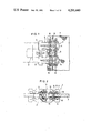
- FIG. 6 is a schematic plan view of a coupling element assembly according to the invention as it is continuously produced on a molding apparatus;
- FIG. 7 is a fragmentary cross-sectional view taken along section line 7--7 of FIG. 6;
- FIG. 8 is a longitudinal cross section view of a coupling element formed on the molding apparatus shown in FIGS. 6 and 7;
- FIG. 9 is an enlarged cross section view of a portion of a warp-knit elongate web which is located between adjacent coupling element leg portions;
- FIG. 10 is an end elevation view, with parts in cross section, of a modified coupling element assembly
- FIG. 11 is a view similar to FIG. 10, showing another modified coupling element assembly
- FIG. 12 is an end elevational view, partly in cross section, of a modified coupling element assembly bonded to a slide fastener stringer tape;
- FIG. 13 is an end elevation view of a modified coupling element assembly with coupling element leg portions fused together;
- FIG. 14 is a fragmentary cross section view of a molding apparatus for forming the coupling element assembly shown in FIG. 13;
- FIG. 15 is an end elevation view of a coupling element assembly produced on the molding apparatus of FIG. 14;
- FIG. 16 is an end elevation view illustrative of the way in which the coupling element leg portions are fused together;
- FIG. 17 is a fragmentary plan view of the coupling element assembly of FIG. 13 as woven into a woven-fabric stringer tape;
- FIG. 18 is a transverse cross section view of the coupling element assembly of FIG. 17;
- FIG. 19 is a fragmentary plan view of a coupling element assembly as knit into a knitted-fabric stringer tape
- FIG. 20 is a cross section view taken along section line 20--20 of FIG. 19;
- FIGS. 21 through 30 are point diagrams illustrating embodiments of warp knit elongate webs
- FIG. 31 is a fragmentary plan view of a slide fastener stringer
- FIG. 32 is a transverse cross section view of the slide fastener stringer of FIG. 31, illustrating the way in which the coupling element assembly is bent into a U shape;
- FIG. 33 is a point diagram for a knitted slide fastener stringer
- FIG. 34 is a point diagram for a knitted slide fastener stringer
- FIG. 35 is a point diagram similar to FIG. 34, for another embodiment
- FIGS. 36 through 38 are end elevation views of different embodiments of knitted slide fastener stringers
- FIG. 39 is a point diagram for another knitted slide fastener stringer
- FIG. 40 is an end elevation view, partly cut away, of the knitted slide fastener stringer shown in FIG. 39, folded over on itself;
- FIG. 41 is a schematic plan view of a plurality of the knitted slide fastener stringers of FIG. 33, connected together by connecting threads.
- a coupling element assembly 1 includes a row of laterally spaced coupling elements 2 of synthetic resin, each having a coupling head portion 3 and a pair of leg portions 4, 5 extending from the coupling head portion 3, and a warp-knit elongate structure 6 extending transversely of the laterally spaced coupling elements 2 having longitudinal portions embedded in the coupling elements 2.
- the coupling element assembly 1 has a substantially U-shaped cross section and is attached astride a longitudinal marginal edge portion of a slide fastener stringer tape 7 by means of a thread with sewing stitches 8.
- the row of coupling elements 2 is engageable with a companion row of coupling element 2, shown in broken lines, to close a slide fastener.
- the warp-knit elongate structure 6 comprises a group of first threads 9, 10, 11 and 12 forming a plurality of wales 13, 14, 15 and 16 of chain stitches, respectively, and a pair of second threads 17, 18 interlaced with the wales 13, 14 and with the wales 15, 16, respectively, thereby providing a pair of warp-knit elongate webs 19, 20 spaced laterally from each other.
- Each of the second threads 17, 18 has a pattern of 0--0/2--2.
- the warp-knit elongate structure 6 further includes a pair of sets of third threads 21,22 interlaced with the wales 13, 14, 15 and 16 and having opposite patterns of 0--0/1--1/0--0/5--5/4--45--5 and 5--5/4--4/5--5/0--0/1--1/0--0, respectively.
- the warp-knit elongate webs 19, 20 have longitudinal portions extending through and embedded in the leg portions 4, 5 of each of the coupling elements 2.
- the pair of sets of third threads 21, 22 have a plurality of parallel portions 23 spaced longitudinally on the first threads 9, 10, 11 and 12 and extending transversely of the wales 13, 14, 15 and 16.
- the parallel spaced portions 23 are embedded in the coupling elements 2 and extend substantially the full length of the coupling elements 2.
- the coupling element assembly 1 prior to being bent into a U shape ready for attachment to a stringer tape, the coupling element assembly 1 has a ladder-like structure.
- Each of the warp-knit webs 19, 20 also has a ladder-like structure which is composed of the wales 13, 14 or 15, 16 interconnected by the second thread 17 or 18.
- the leg portions 4, 5 of the coupling elements 2 are fastened to the webs 19, 20 with an increased degree of bonding strength.
- the warp-knit webs 19, 20 allow material of the coupling elements 2 to enter into their interstices, and have a roughened surface engaging the coupling elements 2, so that the coupling elements 2 can be anchored in place on the webs 19, 20.
- the coupling element assembly 1 shown in FIG. 3 is folded on itself about a longitudinal axis 24 before the assembly 1 is mounted on a stringer tape.
- the coupling element assembly 1 is continuously produced on a molding apparatus 25 shown in FIGS. 6 and 7.
- the molding apparatus 25 has a molding wheel 26 having a plurality of elongate mold cavities 27 in its periphery.
- the mold cavities 27 are closed by an injection shoe 28 having a sprue or passageway 29 through which molten synthetic resin is forced into mold cavities 27.
- the molding wheel 26 has in its periphery a pair of annular grooves (not shown) intersecting the end portions of the elongate mold cavities 27 corresponding to the leg portions 4, 5 of the coupling elements 2 for receiving the warp-knit webs 19, 20.
- the warp-knit elongate structure 6 is placed in the mold cavities 27 closed by the closed shoe 28 as shown in FIG. 7, and molten synthetic resin is forced into the mold cavities 27.
- the injected synthetic resin is molded around the warp-knit webs 19, 20 and the transverse portions 23 of the third threads 21, 22.
- the coupling element assembly 1 is continuously produced as the molding wheel 26 is being rotated in the direction of the arrow 30 (FIG. 6).
- the coupling element assembly 1, as it is formed, is discharged in the direction of the arrow 31 in timed relation with the rotation of the molding wheel 26.
- the portions 32, 33 of the warp-knit elongate webs 19, 20, which are located between adjacent coupling elements 2, can be impregnated with molten synthetic resin.
- a slight clearance between the molding wheel 26 and the injection shoe 28 allows a thin layer 34 of synthetic resin to be formed in an area surrounded by the web portions 32, 33 and the coupling elements 2, 2 disposed adjacent to each other.
- the warp-knit structure 6 shown in FIG. 2 is disposed with the wales 13, 14, 15 and 16 directed away from the stringer tape 7.
- a modified warp-knit structure 35 illustrated in FIG. 10 has its wales 36 directed toward the stringer tape 7 and lying substantially flush with the opposed faces 37, 38 of the coupling element leg portions 4, 5.
- FIG. 11 shows another modification in which the wales 39 of a warp-knit structure 40 extend toward a stringer tape 41 beyond the opposed faces 42, 43 of the coupling element leg portions 4, 5.
- the stringer tape 41 has an elongate bulged portion 44 that is placed in a space 45 between the wales 39 on each of the leg portions 4, 5.
- each of coupling elements 46 has a pair of leg portions 47, 48 including opposed thickened layers 49, 50, respectively, bonded to a stringer tape 51 by welding or adhesive bonding.
- FIG. 13 Another modified coupling element assembly 52 illustrated in FIG. 13 comprises a plurality of coupling elements 53 each having a pair of leg portions 54, 55 including opposed faces 56, 57, respectively, integrally fused together or bonded together by an adhesive.
- a warp-knit elongate structure 58 includes a pair of wales 59,60 embedded in the coupling element leg portion 54 and a pair of wales 61, 62 embedded in the coupling element leg portion 55.
- FIG. 14 illustrates an injection molding apparatus 63 for forming the coupling element assembly 52 of FIG. 13.
- the injection molding apparatus 63 includes a molding wheel 64 having in its periphery a plurality of mold cavities 65 and a pair of annular grooves 66, 67 extending across the mold cavities 65 for receiving the pairs of wales 59, 60 and 61, 62, respectively.
- the annular grooves 66, 67 have a bottom slanted with respect to the peripheral surface of the molding wheel 64, so that the pairs of wales 59, 60 and 61, 62 as placed in the grooves 66, 67 are inclined with the outer wales 59, 62 positioned more deeply in the mold cavities 65 than the inner wales 60, 61.
- Each coupling element 70 of the coupling element assembly 52 of FIG. 15 includes a pair of relatively thick layers 71,72 of synthetic resin on the outer wales 59, 62.
- the layers 71, 72 serve to define the opposite faces 56, 57, respectively.
- the coupling element assembly 52 is folded on itself along its longitudinal axis with an ultrasonic welding horn 73 placed between and in contact with the layers 71, 72 (FIG. 16). The ultrasonic welding horn 73 is then energized to fuse the layers 71, 72 together, whereupon the coupling element assembly 52 illustrated in FIG. 13 is produced.
- the inner wales 60, 61 are impregnated less with synthetic resin than the outer wales 59, 62, and, therefore, are more stretchable longitudinally than the outer wales 59, 62.
- Such an increased degree of stretchability of the inner wales 60, 61 permits the coupling heads of the coupling elements 70 to shift laterally enough for smooth engagement and disengagement between a pair of interengageable rows of coupling elements.
- FIGS. 17 and 18 show the coupling element assembly 52 of FIG. 13 woven into a longitudinal edge of a woven-fabric stringer tape 74.
- the woven stringer tape 74 includes a weft thread 75 extending around exposed portions of the warp-knit structure 58 which are located between adjacent coupling elements 70.
- a core thread 76 of stranded yarns extends longitudinally through the coupling element assembly 52 and is disposed between the inner wales 60, 61 of the warp-knit structure 58. The core thread 76 is retained in position by engagement with the weft thread 75 surrounding the warp-knit structure 58.
- a coupling element assembly 77 may be knit into a longitudinal edge of a knit-fabric stringer tape 78.
- the stringer tape 78 is composed of a plurality of threads 79 forming wales of chain stitches having a pattern of 1--0/0--1, a plurality of threads 80 having a pattern of 1--0/1--2, a plurality of threads 81 having a pattern of 0--0/4--4, and a longitudinal warp cord 82 disposed between an outermost pair of wales 83, 84.
- the coupling element assembly 77 includes a longitudinal core thread 85 extending therethrough and is fastened in position by the outermost wale 84, a thread 86 extending between the wales 83, 84 in a pattern of 1--0/4--3, and one of the threads 81 extending between the outermost wales 83, 84.
- the portions of a warp-knit structure 87 of the coupling element assembly 77, which are positioned between adjacent coupling elements 88, are surrounded by the thread 86.
- the outermost wale 84 is displaced away from the coupling head portions of the coupling elements 88 and is held against a lower one of the leg portions of each coupling element 88 by being pulled by the thread 86 and said one of the threads 81.
- the threads 81 and 86 are preferably comprised of yarns of high thermal shrinkability for better fastening of the coupling elements 88 to the stringer tape 78 and for better tensioning of the outermost wale 84 against the lower leg portions of the coupling elements 88.
- a warp-knit elongate structure 89 shown in FIG. 21 comprises a pair of warp-knit elongate webs 90, 91 including two pairs of first threads 92, 93, 94 and 95 each forming a wale of chain stitches in a pattern of 0--1/1--0.
- Each of the webs 90, 91 has a second thread 96 interknitted with the wales in a pattern of 2--0/0--2.
- a pair of third threads 97, 98 are interlaced with the inner threads 93, 94 in opposite symmetrical patterns of 4--4/3--3/4--4/0-0/1--1/0--0 and 0--0/1--1/0--0/4--4/3--3/4--4.
- a warp-knit elongate structure 99 is illustrated in FIG. 22 and includes a pair of sets of third threads 100, 101 and 102, 103 interlaced with two pairs of first threads 104, 105, 106 and 107 in opposite symmetrical patterns of 5--5/4--4/5--5/0--0/1--1/0--0 and 0--0/1--1/0--0/5--5/4--4/5--5.
- a pair of warp-knit elongate webs 109, 110 have two pairs of first threads 111, 112, 113 and 114 each forming a wale of chain stitches in a pattern of 0--1/1--0.
- a pair of second threads 115, 116 are interknitted with the pairs of first threads 111, 112 and 113, 114, respectively, in a pattern of 1--0/1--2.
- a warp thread 117 extends longitudinally in and along each of the first threads 111, 112, 113 and 114 in a pattern of 1--1/0--0.
- a pair of third threads 118, 119 are interlaced with the first threads 111, 112, 113 and 114 in a pattern of 5--5/4--4/5--5/0--0/ 1--1/0--0.
- a warp-knit elongate structure 120 of FIG. 24 includes a pair of warp-knit elongate webs 121, 122 comprising two pairs of first threads 123, 124, 125 and 126 having a pattern of 0--1/ 1--0, and a pair of second threads 127, 128 interknitted with the pairs of first threads 123, 124 and 125, 126, respectively.
- the warp-knit structure 120 has a pair of third threads 129, 130 interlaced with the outer first threads 123, 126 in opposite symmetrical patterns of 0--0/6--6/6--6/0--0 and 6--6/0--0/0--0/6--6.
- a warp-knit elongate structure 131 illustrated in FIG. 25 is comprised of a pair of warp-knit elongate webs 132, 133 including two pairs of first threads 134, 135, 136 and 137 having a pattern of 0--1/1--0. Interknitted with each pair of the first threads 134, 135 or 136, 137 is a second thread 138 having a pattern of 2--0/0--2.
- a third thread 139 is interlaced with the outer first threads 134, 137 in a pattern of 6--6/5--5/6--6/0--0/1--1/0--0.
- a pair of reinforcing warp threads 140, 141 extend longitudinally between the pair of first threads 134, 135 and between the pair of first threads 136, 137.
- a warp-knit elongate structure 142 shown in FIG. 26 is similar to the structure 99 of FIG. 22 and differs therefrom only in that the warp-knit structure 142 includes a pair of reinforcing warp threads 143, 144.
- a warp-knit elongate structure 145 is shown in FIG. 27 as comprising a pair of warp-knit elongate webs 146, 147 including two pairs of first threads 148, 149, 150 and 151 having a pattern of 0--1/1--0.
- a pair of second threads 152, 153 are interknitted with the pair of first threads 148, 149 and with the pair of first threads 150, 151, respectively.
- the warp-knit elongate webs 146, 147 has a pair of reinforcing warp threads 154, 155 extending longitudinally between the pair of first threads 148, 149 and between the pair of first threads 150, 151, respectively.
- a pair of third threads 156, 157 are interknitted with the first threads 148, 149, 150 and 151 in a pattern of 4--5/0--1.
- the third threads 156, 157 are preferably made of thermally shrinkable yarns.
- the portions 158, 159 of the third threads 156, 157 which are to be positioned between adjacent coupling elements 160, 161 are shrunk when subjected to heat during a dyeing process, with the result that the portions 158, 159 will not interfere with proper interengagement between a pair of rows of coupling elements.
- a warp-knit elongate structure 162 shown in FIG. 28 comprises a pair of warp-knit elongate webs 163, 164 including a pair of first threads 165, 166 having a pattern of 0--1/1--0.
- a pair of second threads 167, 168 extend longitudinally in and along the first threads 165, 166 in a pattern of 1--1/0--0.
- a pair of third threads 169, 170 are interlaced with the frst threads 165, 166 in opposite symmetrical patterns of 0--0/1--1/0--0/4--4/3--3/4--4 and 4--4/3--3/4--4/0--0/1--1/0--0.
- a warp-knit elongate structure 171 illustrated in FIG. 29 includes a pair of warp-knit elongate webs 172, 173 comprising two pairs of first threads 174, 175, 176 and 177 having a pattern of 0--1/1--0.
- a pair of second threads 178, 179 are interknitted with the pair of first threads 174, 175 and with the pair of first threads 176, 177, respectively.
- the warp-knit structure 171 includes a pair of third threads 180, 181 interlaced with the first threads 174, 175, 176 and 177 in a pattern of 5--5/0--0.
- FIG. 30 shows a warp-knit elongate web 182 comprising a pair of first threads 183, 184 having a pattern of 0--1/1--0, a second thread 185 interknitted with the first threads 183, 184 in a pattern of 2--0/0--2, and a warp thread 186 interlaced with the first threads 183, 184 in a pattern of 2--2/0--0.
- a pair of such warp-knit elongate webs 182 are embedded in the leg portions of a row of laterally spaced coupling elements.
- a coupling element assembly using a pair of the warp-knit elongate webs 182 has no threads embedded longitudinally in the coupling elements, the coupling elements are securely fastened to the warp-knit webs 184 because the warp-knit webs 184 have roughened surfaces with interstices filled by material of the coupling elements.
- a slide fastener stringer shown in FIGS. 31 and 32 has a stringer tape 187 of a warp-knit fabric interknitted with a warp-knit elongate structure 188 having portions embedded in a row of coupling elements 189 of synthetic resin.
- the row of coupling elements 189 is folded on itself about a longitudinal axis.
- FIG. 33 illustrates an embodiment of a slide fastener stringer 190 having a stringer tape 191 and a coupling element assembly 192.
- the stringer tape 191 is composed of a plurality of threads 193 having a pattern of 0--1/1--0, a plurality of threads 194 having a pattern of 1--0/1--2, and a plurality of threads 195 having a pattern of 4--5/1--0.
- the coupling element assembly 192 includes a warp-knit elongate structure 196 extending along one longitudinal edge of the stringer tape 191.
- the warp-knit elongate structure 196 comprises two pairs of first threads 197 having a pattern of 0--1/1--0, a pair of second threads 198 having a pattern of 1--0/1--2 interknitted with the pairs of first threads 197, and a pair of longitudinal reinforcing warp threads 199 each extending between the respective pair of first threads 197.
- a pair of sets of third threads 200 are interlaced with the pairs of first threads 197 in opposite symmetrical patterns of 0--0/1--1/0--0/5--5/4--4/5--5 and 5--5/4--4/5--5/0--0/1--1/0--0.
- the stringer tape 191 and the warp-knit elongate structure 196 are interconnected by one of the threads 194 and two of the threads 195.
- a slide fastener stringer 201 shown in FIG. 34 differs from the slide fastener stringer 190 shown in FIG. 33 in that the stringer 201 has no reinforcing warp threads and has two pairs of more rigid first threads 202 in its warp-knit elongate structure 203.
- Each of the first threads 202 is preferably composed of a thickened yarn or stranded yarns.
- FIG. 35 shows a slide fastener stringer 204 according to another embodiment, in which a pair of third threads 205, 206 have a pattern of 4--5/1--0.
- a core material 207 is disposed between a pair of leg portions 208, 209 of each coupling element 210.
- the leg portions 208, 209 are sewn to the core material 207 by sewing stitches 211 such as lockstitches or double chain stitches.
- FIG. 37 shows a core material 212 secured between a pair of leg portions 213, 214 of each coupling element 215 by overlock stitches 216.
- each coupling element 220 is fused or bonded together and are fastened together by sewing stitches 221.
- FIGS. 36 through 38 are applicable to the slide fastener stringers of FIGS. 31 through 35.
- FIGS. 39 and 40 show a slide fastener stringer 222 comprising a coupling element assembly 223 having a warp-knit elongate structure 224, and a pair of warp-knit fabrics 225, 226 disposed one on each side of and interknitted with the warp-knit elongate structure 224.
- the coupling element assembly 223 is folded on itself about its longitudinal axis, the warp-knit fabrics 225, 226 are superimposed on each other, forming a stringer tape 227.
- a plurality of slide fastener stringers 228 each having an integral coupling element assembly 229 according to the present invention can be produced simultaneously as shown in FIG. 41.
- the slide fastener stringers 228 are laterally connected by water-soluble connecting threads 230, so that the stringers 228 can be separated by being dipped into water as in a dyeing process.
- the embedded parallel spaced portions stabilize the coupling elements positionally against any displacement particularly in the transverse direction thereof.
- This reinforcing arrangement is advantageous especially where the coupling elements are made of an unstretched plastic material that is easily deformable, ductile and soft.
Landscapes
- Engineering & Computer Science (AREA)
- Mechanical Engineering (AREA)
- Textile Engineering (AREA)
- Knitting Of Fabric (AREA)
- Slide Fasteners (AREA)
- Extrusion Moulding Of Plastics Or The Like (AREA)
- Ropes Or Cables (AREA)
- Prostheses (AREA)
- Slide Fasteners, Snap Fasteners, And Hook Fasteners (AREA)
Applications Claiming Priority (2)
| Application Number | Priority Date | Filing Date | Title |
|---|---|---|---|
| JP53-67434 | 1978-06-05 | ||
| JP6743478A JPS54159040A (en) | 1978-06-05 | 1978-06-05 | Fastener element train made of synthetic resin |
Publications (1)
| Publication Number | Publication Date |
|---|---|
| US4291440A true US4291440A (en) | 1981-09-29 |
Family
ID=13344798
Family Applications (1)
| Application Number | Title | Priority Date | Filing Date |
|---|---|---|---|
| US06/041,329 Expired - Lifetime US4291440A (en) | 1978-06-05 | 1979-05-22 | Molded coupling element assembly |
Country Status (16)
| Country | Link |
|---|---|
| US (1) | US4291440A (ja) |
| JP (1) | JPS54159040A (ja) |
| AU (1) | AU525642B2 (ja) |
| BE (1) | BE876780A (ja) |
| BR (1) | BR7903577A (ja) |
| CA (1) | CA1121571A (ja) |
| CH (1) | CH643717A5 (ja) |
| DE (1) | DE2922805C2 (ja) |
| ES (1) | ES481786A1 (ja) |
| FR (1) | FR2437799A1 (ja) |
| GB (1) | GB2023222B (ja) |
| HK (1) | HK32687A (ja) |
| IT (1) | IT1118759B (ja) |
| MY (1) | MY8600198A (ja) |
| NL (1) | NL7904385A (ja) |
| SG (1) | SG48385G (ja) |
Cited By (11)
| Publication number | Priority date | Publication date | Assignee | Title |
|---|---|---|---|---|
| US4392363A (en) * | 1979-11-27 | 1983-07-12 | Yoshida Kogyo K. K. | Slide fastener stringer with vent holes |
| US4401138A (en) * | 1980-08-08 | 1983-08-30 | Yoshida Kogyo K. K. | Woven slide fastener stringer |
| US4418449A (en) * | 1979-10-17 | 1983-12-06 | Optilon W. Erich Heilmann Gmbh | Slide fastener |
| US4442685A (en) * | 1980-06-25 | 1984-04-17 | Yoshida Kogyo K. K. | Slide fastener stringer for knit fabrics |
| US4463486A (en) * | 1979-05-09 | 1984-08-07 | Yoshida Kogyo K. K. | Method of manufacturing a velvet-type fastener web |
| US4490890A (en) * | 1980-09-10 | 1985-01-01 | Yoshida Kogyo K.K. | Separable slide fastener |
| US4562621A (en) * | 1983-03-03 | 1986-01-07 | Yoshida Kogyo K.K. | Slide fastener stringer |
| US20080257442A1 (en) * | 2004-07-26 | 2008-10-23 | Ykk Corporation | Slide fastener stringer and method of manufacturing the same |
| US20130174388A1 (en) * | 2010-09-28 | 2013-07-11 | Ykk Corporation | Slide Fastener |
| US20190254388A1 (en) * | 2018-02-19 | 2019-08-22 | Ykk Corporation | Fastener Stringer, Slide Fastener, and Fastener Stringer Attachment Structure |
| US11083255B2 (en) * | 2017-02-02 | 2021-08-10 | Ykk Corporation | Slide fastener-attached product |
Families Citing this family (2)
| Publication number | Priority date | Publication date | Assignee | Title |
|---|---|---|---|---|
| AU529365B2 (en) * | 1980-09-18 | 1983-06-02 | Yoshida Kogyo K.K. | Warp-knit slide fastener stringer tape |
| CA1173635A (en) * | 1980-12-02 | 1984-09-04 | Yoshida Kogyo K.K. | Adjustable fastener |
Citations (11)
| Publication number | Priority date | Publication date | Assignee | Title |
|---|---|---|---|---|
| US3179996A (en) * | 1963-09-03 | 1965-04-27 | Ries G M B H Bekleidungsversch | Concealed slide fastener |
| NL6703533A (ja) * | 1966-03-05 | 1967-09-06 | ||
| NL6804649A (ja) * | 1967-04-04 | 1968-10-07 | ||
| US3414948A (en) * | 1966-09-29 | 1968-12-10 | Scovill Manufacturing Co | Thermoplastic strips for sliding clasp fasteners |
| US3964137A (en) * | 1973-05-08 | 1976-06-22 | Yoshida Kogyo Kabushiki Kaisha | Slide fastener |
| US4033014A (en) * | 1976-05-17 | 1977-07-05 | Textron, Inc. | Continuous molded slide fastener stringer and method and apparatus for manufacture |
| US4075874A (en) * | 1976-05-20 | 1978-02-28 | Optilon W. Erich Heilmann Gmbh | Slide-fastener stringer half with knitted-in coupling elements and method of making same |
| US4080691A (en) * | 1976-09-17 | 1978-03-28 | Textron Inc. | Molded element tape support for invisible slide fastener and method of manufacture |
| US4123830A (en) * | 1976-09-02 | 1978-11-07 | Yoshida Kogyo K.K. | Slide fastener stringer |
| US4140157A (en) * | 1976-09-17 | 1979-02-20 | Textron Inc. | Molded coupling element for woven slide fastener with twist preventing projection |
| US4171556A (en) * | 1976-09-17 | 1979-10-23 | Textron Inc. | Slide fastener with molded elements and method of manufacture |
-
1978
- 1978-06-05 JP JP6743478A patent/JPS54159040A/ja active Granted
-
1979
- 1979-05-22 US US06/041,329 patent/US4291440A/en not_active Expired - Lifetime
- 1979-05-24 AU AU47380/79A patent/AU525642B2/en not_active Ceased
- 1979-06-01 FR FR7914089A patent/FR2437799A1/fr active Granted
- 1979-06-04 CA CA000329012A patent/CA1121571A/en not_active Expired
- 1979-06-05 CH CH521779A patent/CH643717A5/de not_active IP Right Cessation
- 1979-06-05 BE BE0/195579A patent/BE876780A/xx not_active IP Right Cessation
- 1979-06-05 BR BR7903577A patent/BR7903577A/pt unknown
- 1979-06-05 DE DE2922805A patent/DE2922805C2/de not_active Expired
- 1979-06-05 GB GB7919588A patent/GB2023222B/en not_active Expired
- 1979-06-05 ES ES481786A patent/ES481786A1/es not_active Expired
- 1979-06-05 NL NL7904385A patent/NL7904385A/xx not_active Application Discontinuation
- 1979-06-05 IT IT68218/79A patent/IT1118759B/it active
-
1985
- 1985-06-19 SG SG48385A patent/SG48385G/en unknown
-
1986
- 1986-12-30 MY MY198/86A patent/MY8600198A/xx unknown
-
1987
- 1987-04-23 HK HK326/87A patent/HK32687A/xx unknown
Patent Citations (11)
| Publication number | Priority date | Publication date | Assignee | Title |
|---|---|---|---|---|
| US3179996A (en) * | 1963-09-03 | 1965-04-27 | Ries G M B H Bekleidungsversch | Concealed slide fastener |
| NL6703533A (ja) * | 1966-03-05 | 1967-09-06 | ||
| US3414948A (en) * | 1966-09-29 | 1968-12-10 | Scovill Manufacturing Co | Thermoplastic strips for sliding clasp fasteners |
| NL6804649A (ja) * | 1967-04-04 | 1968-10-07 | ||
| US3964137A (en) * | 1973-05-08 | 1976-06-22 | Yoshida Kogyo Kabushiki Kaisha | Slide fastener |
| US4033014A (en) * | 1976-05-17 | 1977-07-05 | Textron, Inc. | Continuous molded slide fastener stringer and method and apparatus for manufacture |
| US4075874A (en) * | 1976-05-20 | 1978-02-28 | Optilon W. Erich Heilmann Gmbh | Slide-fastener stringer half with knitted-in coupling elements and method of making same |
| US4123830A (en) * | 1976-09-02 | 1978-11-07 | Yoshida Kogyo K.K. | Slide fastener stringer |
| US4080691A (en) * | 1976-09-17 | 1978-03-28 | Textron Inc. | Molded element tape support for invisible slide fastener and method of manufacture |
| US4140157A (en) * | 1976-09-17 | 1979-02-20 | Textron Inc. | Molded coupling element for woven slide fastener with twist preventing projection |
| US4171556A (en) * | 1976-09-17 | 1979-10-23 | Textron Inc. | Slide fastener with molded elements and method of manufacture |
Cited By (16)
| Publication number | Priority date | Publication date | Assignee | Title |
|---|---|---|---|---|
| US4463486A (en) * | 1979-05-09 | 1984-08-07 | Yoshida Kogyo K. K. | Method of manufacturing a velvet-type fastener web |
| US4418449A (en) * | 1979-10-17 | 1983-12-06 | Optilon W. Erich Heilmann Gmbh | Slide fastener |
| US4392363A (en) * | 1979-11-27 | 1983-07-12 | Yoshida Kogyo K. K. | Slide fastener stringer with vent holes |
| US4442685A (en) * | 1980-06-25 | 1984-04-17 | Yoshida Kogyo K. K. | Slide fastener stringer for knit fabrics |
| US4401138A (en) * | 1980-08-08 | 1983-08-30 | Yoshida Kogyo K. K. | Woven slide fastener stringer |
| US4490890A (en) * | 1980-09-10 | 1985-01-01 | Yoshida Kogyo K.K. | Separable slide fastener |
| US4562621A (en) * | 1983-03-03 | 1986-01-07 | Yoshida Kogyo K.K. | Slide fastener stringer |
| US20080257442A1 (en) * | 2004-07-26 | 2008-10-23 | Ykk Corporation | Slide fastener stringer and method of manufacturing the same |
| US20130174388A1 (en) * | 2010-09-28 | 2013-07-11 | Ykk Corporation | Slide Fastener |
| US9237782B2 (en) * | 2010-09-28 | 2016-01-19 | Ykk Corporation | Slide fastener |
| US11083255B2 (en) * | 2017-02-02 | 2021-08-10 | Ykk Corporation | Slide fastener-attached product |
| US11089846B2 (en) * | 2017-02-02 | 2021-08-17 | Ykk Corporation | Slide fastener-attached product, element member and manufacturing method of slide fastener-attached product |
| US11206901B2 (en) | 2017-02-02 | 2021-12-28 | Ykk Corporation | Slide fastener-attached product, element member and manufacturing method of slide fastener-attached product |
| US11406165B2 (en) | 2017-02-02 | 2022-08-09 | Ykk Corporation | Slide fastener-attached product |
| US20190254388A1 (en) * | 2018-02-19 | 2019-08-22 | Ykk Corporation | Fastener Stringer, Slide Fastener, and Fastener Stringer Attachment Structure |
| US10602811B2 (en) * | 2018-02-19 | 2020-03-31 | Ykk Corporation | Fastener stringer, slide fastener, and fastener stringer attachment structure |
Also Published As
| Publication number | Publication date |
|---|---|
| HK32687A (en) | 1987-05-01 |
| FR2437799A1 (fr) | 1980-04-30 |
| MY8600198A (en) | 1986-12-31 |
| JPS5735642B2 (ja) | 1982-07-30 |
| JPS54159040A (en) | 1979-12-15 |
| GB2023222B (en) | 1982-09-02 |
| AU4738079A (en) | 1979-12-13 |
| DE2922805A1 (de) | 1979-12-13 |
| NL7904385A (nl) | 1979-12-07 |
| GB2023222A (en) | 1979-12-28 |
| SG48385G (en) | 1986-01-17 |
| CA1121571A (en) | 1982-04-13 |
| BR7903577A (pt) | 1980-01-22 |
| AU525642B2 (en) | 1982-11-18 |
| CH643717A5 (en) | 1984-06-29 |
| FR2437799B1 (ja) | 1982-11-05 |
| IT1118759B (it) | 1986-03-03 |
| BE876780A (fr) | 1979-10-01 |
| ES481786A1 (es) | 1980-02-16 |
| IT7968218A0 (it) | 1979-06-05 |
| DE2922805C2 (de) | 1982-07-01 |
Similar Documents
| Publication | Publication Date | Title |
|---|---|---|
| US6728998B2 (en) | Woven hook and loop fastening | |
| US4823446A (en) | Fluid-tight slide fastener stringer | |
| US4291440A (en) | Molded coupling element assembly | |
| US4601085A (en) | Water-resistant slide fastener stringer | |
| US6443187B1 (en) | Aligning woven loop elements to form mounting sleeves | |
| US8011070B2 (en) | Curved slide fastener | |
| KR100399517B1 (ko) | 면 파스너 | |
| KR970008149B1 (ko) | 니트 슬라이드 파스너 | |
| US3456306A (en) | Slide fastener with continuous coupling element | |
| CA1062888A (en) | Molded coupling element for woven slide fastener with twist preventing projection | |
| CA1188077A (en) | Separable slide fastener | |
| JPH0779815A (ja) | スライドファスナー用テープおよびスライドファスナー | |
| CA1137738A (en) | Stringer tape for slide fasteners | |
| US3487510A (en) | Slide-fastener assembly and method of making same | |
| CA1113835A (en) | Woven stringer for slide fasteners | |
| US4067208A (en) | Warp-knit slide-fastener support tape and method of making same | |
| US3505710A (en) | Slide-fastener assembly | |
| US4251912A (en) | Apparatus for producing a coupling element assembly for slide fasteners | |
| CA1173634A (en) | Separable slide fastener | |
| US3490108A (en) | Slide fastener | |
| CA1176038A (en) | Slide fastener stringer | |
| US3494008A (en) | Slide fastener | |
| US4297770A (en) | Slide fastener and method of making same | |
| US4675951A (en) | Slide fastener stringer | |
| US4409802A (en) | Warp-knit stringer tape for slide fasteners |
Legal Events
| Date | Code | Title | Description |
|---|---|---|---|
| STCF | Information on status: patent grant |
Free format text: PATENTED CASE |
|
| AS | Assignment |
Owner name: YKK CORPORATION, JAPAN Free format text: CHANGE OF NAME;ASSIGNOR:YOSHIDA KOGYO K.K.;REEL/FRAME:007317/0327 Effective date: 19940801 |