US4289357A - Hollow cutting head - Google Patents
Hollow cutting head Download PDFInfo
- Publication number
- US4289357A US4289357A US06/112,614 US11261480A US4289357A US 4289357 A US4289357 A US 4289357A US 11261480 A US11261480 A US 11261480A US 4289357 A US4289357 A US 4289357A
- Authority
- US
- United States
- Prior art keywords
- cutting head
- cutting
- gap
- water
- cooling water
- Prior art date
- Legal status (The legal status is an assumption and is not a legal conclusion. Google has not performed a legal analysis and makes no representation as to the accuracy of the status listed.)
- Expired - Lifetime
Links
Images

Classifications
-
- E—FIXED CONSTRUCTIONS
- E21—EARTH OR ROCK DRILLING; MINING
- E21D—SHAFTS; TUNNELS; GALLERIES; LARGE UNDERGROUND CHAMBERS
- E21D9/00—Tunnels or galleries, with or without linings; Methods or apparatus for making thereof; Layout of tunnels or galleries
- E21D9/10—Making by using boring or cutting machines
- E21D9/1006—Making by using boring or cutting machines with rotary cutting tools
- E21D9/1013—Making by using boring or cutting machines with rotary cutting tools on a tool-carrier supported by a movable boom
- E21D9/102—Making by using boring or cutting machines with rotary cutting tools on a tool-carrier supported by a movable boom by a longitudinally extending boom being pivotable about a vertical and a transverse axis
- E21D9/1026—Making by using boring or cutting machines with rotary cutting tools on a tool-carrier supported by a movable boom by a longitudinally extending boom being pivotable about a vertical and a transverse axis the tool-carrier being rotated about a transverse axis
-
- E—FIXED CONSTRUCTIONS
- E21—EARTH OR ROCK DRILLING; MINING
- E21C—MINING OR QUARRYING
- E21C35/00—Details of, or accessories for, machines for slitting or completely freeing the mineral from the seam, not provided for in groups E21C25/00 - E21C33/00, E21C37/00 or E21C39/00
- E21C35/22—Equipment for preventing the formation of, or for removal of, dust
- E21C35/23—Distribution of spraying-fluids in rotating cutter-heads
Definitions
- the cutting head is rotating and the water must be supplied to the cutting head via the carrier for the cutting head, i.e. generally via the cutting arm.
- the cutting head is provided with a big number of bits what requires a big number of nozzles on the cutting head which nozzles must be connected with a chamber from which the water is supplied to the nozzles. Also such an arrangement involves difficulties.
- the invention now refers to a hollow cutting head provided with bits and adapted to be rotatably supported on a carrier protruding into the hollow cutting head and being provided with cooling water nozzles which are directed against the bits, noting that the cooling water can be supplied to the cooling water nozzles via the cutting head body and passages provided therein, and the invention aims at providing an effective seal of the water supply system even with high water supply pressures as for instance pressures exceeding 300 bar and particularly exceeding 400 bar and further aims at establishing a simple water path for feeding the nozzles with water.
- the invention essentially consists in that a distributing chamber is provided within the cutting head and arranged in alignment with a water supply tube rigidly arranged in the axis of the carrier, noting that the water supply tube is opening into the distributing chamber and is adapted to be sealingly connected to the distributing chamber of the rotatably supported cutting head body, in that at least one annular gap extending in axial direction of the cutting head is provided within the cutting head body, in that said annular gap is connected to the distributing chamber over at least one passage and in that passages are opening into the annular gap which lead to the cooling water nozzles.
- the nozzles can be connected with the water supply chamber via approximately radially extending bores all of which are opening into the annular gap or into the annular gaps.
- the supply pressure of the water can thus be made substantially fully effective at the nozzles and any clogging of the nozzles is counteracted.
- the walls of the annular gap or of the annular gaps have approximately cylindrical shape in a cutting head. Such a cylindrical wall can without difficulties resist even high pressures.
- the stress on the end walls delimiting the ring gap is however unfavourable. This applies particularly in a known embodiment in which the cutting head body is composed of axially superimposed discs which are mutually welded. In this case the weld seams are stressed by the load acting on the end walls of the annular gap.
- the areas of the end walls of an annular gap are, however, substantially smaller than the cylindrical walls delimiting the annular gap so that the total pressure acting on these end walls can without further be resisted even with high supply pressure of the water.
- the surface area of one end wall delimiting the annular gap is only a fraction, preferably 1/10 to 1/20 of the surface area of the circumferential surface of the annular gap, noting that the annular gap extends over at least 1/3 of the axial length of the cutting head. This results in a simple construction of high pressure resistance.
- the inventive construction of the cutting head provides for the possibility to supply to the cutting head cooling water under a considerably high pressure and to make this pressure effective at the nozzles without substantial losses, so that the nozzles are reliably prevented from becoming clogged.
- the cooling water is supplied to the cutting head under a pressure of more than 300 bar, preferably under a pressure of approximately 400 bar. In cutting heads of known constructions it was not possible to increase the supply pressure of the cooling water for the cutting head over 20 to 30 bar.
- the water supply tube can sealingly be passed through a wall rotating with the cutting head and delimiting a chamber separated from the oil chamber of the cutting head drive means and from the anti-friction bearings carrying the cutting head.
- This has as an effect that with only a minor untightness of the seal between the stationary constructional part and the rotating cutting head, the water passing through the untight seal does not immediately enter the lubricating oil circuit.
- this chamber separated from the oil chamber is preferably in connection with the atmosphere so that even with a more considerable untightness no pressure can be built up in this chamber separated from the oil chamber.
- the sealing arranged in the wall rotating with the cutting head is now not subjected to the supply pressure and warrants a complete seal.
- the chamber separated from the oil chamber can be connected to the atmosphere via a check valve opening in direction to the atmosphere and/or a labyrinth seal or the like so that dust and foreign matter are prevented from entering the chamber separated from the oil chamber.
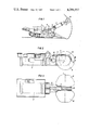
- FIG. 1 shows a cutting machine
- FIGS. 2 and 3 show in a lateral view and a top plan view, respectively, a cutting arm together with the cutting heads and
- FIG. 4 shows a section through one of the cutting heads and of the cutting arm in an enlarged scale and in a section along line IV--IV of FIG. 2.
- the cutting machine 1 has a cutting arm 2 which can be swivelled in upward and downward direction around the horizontal axis 3 and can be laterally swivelled around a vertical axis 4.
- a cutting arm 2 which can be swivelled in upward and downward direction around the horizontal axis 3 and can be laterally swivelled around a vertical axis 4.
- a cooling water conduit 7 is provided along the top surface of the cutting arm 2 and protected against downwardly falling rock by a U-profile 8. This cooling water conduit is passed over the end of the cutting arm 2 and is connected to the cutting arm by a screw connection 9. 10 is a cover plate protecting the foremost portion of the cooling water conduit 7. Cooling water is supplied under high pressure by means of a pump not shown into the cooling water conduit 7.
- a carrier 11 is rigidly connected to the cutting arm and extending into the hollow cutting head body 12 provided with bits.
- the cutting head body 12 is composed of axially superimposed discs 13, 14, 15, 16, 17 which are mutually welded. These discs 13 to 17 surround a cylindrical central portion 18 of the cutting head body and this central portion 18 is welded to the mutually welded discs 13 to 17.
- This welded unit 13 to 17 and 18 is covered by an end portion 19 which is by means of screws 20 screwedly connected to the welded unit 13 to 17 and 18.
- a ring 21 and a plate member 22 are in their turn welded to this end portion 19.
- a central annular part 23 is welded into the plate member 22 and a central insert 24 is screwedly connected with this annular part 23.
- the cooling water is fed to a central cavity 28 within the carrier 11 from the screw connection 9 via a passage 25 on the cutting arm 2 and passages 26 and 27 within the carrier 11 rigidly connected to the cutting arm.
- a tube 29 rigidly connected to the carrier 11 is connected to the central cavity 28 and is in alignment with the axis of the cutting head 6.
- This tube 29 opens into a distributing chamber 30 which is located within the insert 24.
- a sealing 31 the end of this tube 29 is sealingly guided within the insert 24.
- This insert 24 is together with the cutting head rotating around this stationary tube 29. In view of this tube being in alignment with the axis of the cutting head 6, this tube can reliably be sealed by means of the sealing 31.
- the cutting head body is rotatably supported by means of anti-friction bearings 32, 33 and 34 on the carrier 11 rigidly connected to the cutting arm 2.
- the outer bearing ring 35 of the anti-friction bearing 34 is rigidly connected with, for example screwed into the cutting head body and closed by a lid 36.
- a cavity 37 is formed between the lid 36 and the plate member 22.
- Within the interior of the carrier 11 a planet gear not shown is arranged which represents the last gearing step.
- This planet gear and also the anti-friction bearings 32, 33 and 34 are operating within an oil bath which is in connection with the lubricating oil circuit of the gearing.
- the cavity 37 is tightly closed against this oil chamber by means of the lid 36.
- 38 is an overload friction clutch via which the cutting head body composed of the parts 13 to 22 is connected with a hub 39 which is rotatably supported on the carrier 11 by means of the anti-friction bearings 32, 33 and 34.
- the central tube 29 rigidly connected to the carrier is also sealingly guided within the lid 36 by means of a seal 40.
- This has as an effect that any water passing through the sealing 31 can not enter the lubricating oil circuit but only enter into the cavity 37.
- This cavity 37 is in connection with the atmosphere via a passage 41 so that no pressure can be built up within the cavity 37.
- a check valve not shown and opening in outward direction and/or a labyrinth seal can be mounted within this passage 41 so that foreign matter is prevented from entering the cavity 37.
- the cooling water Via a passage 42 the cooling water enters an annular gap 43 and then flows through further passages 44 and 45 to an annular gap 46.
- Said both annular gaps 43 and 46 substantially extend over the whole axial length of a cutting head body.
- the cooling water nozzles not shown are located on the circumference of the cutting head body and each radial passage extending from the circumferential surface in inward direction must open into one of the annular gaps 43 or 46. In the drawing the radial passages 47 and 48 of a plurality of such passages are shown. The passages leading to the further nozzle are not located in the section plane of FIG. 4. All nozzles can thus be supplied with water from these annular gaps 43 and 46.
- the annular gap 46 is located between the central portion 18 and the group of mutually welded discs 13 to 17.
- the annular gap 43 is located between the end portion 19 and the ring 21.
- FIG. 4 also the drive means for the cutting head is schematically shown.
- the toothed end of the drive shaft is designated 51, the teeth of which are cooperating with intermediate tooth gears 53 supported on axes 52 in the carrier 11. These intermediate tooth gears are in engagement with an internal toothing 54 of a hollow wheel forming part of the rotatably supported cutting head 6.
Landscapes
- Engineering & Computer Science (AREA)
- Mining & Mineral Resources (AREA)
- Geology (AREA)
- Life Sciences & Earth Sciences (AREA)
- General Life Sciences & Earth Sciences (AREA)
- Geochemistry & Mineralogy (AREA)
- Environmental & Geological Engineering (AREA)
- Mechanical Engineering (AREA)
- Processing Of Stones Or Stones Resemblance Materials (AREA)
- Excavating Of Shafts Or Tunnels (AREA)
- Dental Tools And Instruments Or Auxiliary Dental Instruments (AREA)
- Nozzles (AREA)
- Drilling And Boring (AREA)
Applications Claiming Priority (2)
| Application Number | Priority Date | Filing Date | Title |
|---|---|---|---|
| AT998/79 | 1979-02-09 | ||
| AT99879A AT359453B (de) | 1979-02-09 | 1979-02-09 | Schraemkopf |
Publications (1)
| Publication Number | Publication Date |
|---|---|
| US4289357A true US4289357A (en) | 1981-09-15 |
Family
ID=3504589
Family Applications (1)
| Application Number | Title | Priority Date | Filing Date |
|---|---|---|---|
| US06/112,614 Expired - Lifetime US4289357A (en) | 1979-02-09 | 1980-01-16 | Hollow cutting head |
Country Status (19)
| Country | Link |
|---|---|
| US (1) | US4289357A (cs) |
| EP (1) | EP0014695B1 (cs) |
| JP (1) | JPS6027359B2 (cs) |
| AR (1) | AR223696A1 (cs) |
| AT (1) | AT359453B (cs) |
| AU (1) | AU535581B2 (cs) |
| BG (1) | BG39298A3 (cs) |
| BR (1) | BR8000808A (cs) |
| CA (1) | CA1124754A (cs) |
| CS (1) | CS256351B2 (cs) |
| DD (1) | DD149101A5 (cs) |
| DE (1) | DE3062997D1 (cs) |
| HU (1) | HU182088B (cs) |
| IN (1) | IN153640B (cs) |
| PL (1) | PL122621B1 (cs) |
| RO (1) | RO86913B1 (cs) |
| SU (1) | SU1187728A3 (cs) |
| YU (1) | YU33180A (cs) |
| ZA (1) | ZA8036B (cs) |
Cited By (14)
| Publication number | Priority date | Publication date | Assignee | Title |
|---|---|---|---|---|
| US4470636A (en) * | 1980-12-24 | 1984-09-11 | Paurat F | Mining machine excavator drum having liquid spray control |
| US4555143A (en) * | 1983-04-11 | 1985-11-26 | Voest-Alpine Aktiengesellschaft | Apparatus for cutting rock |
| US4568127A (en) * | 1982-09-03 | 1986-02-04 | Voest-Alpine Aktiengesellschaft | Cutting head for drift advancing machines |
| US4572583A (en) * | 1982-09-03 | 1986-02-25 | Voest-Alpine Aktiengesellschaft | Cutting head for drift advancing machines and process for producing same |
| US4585275A (en) * | 1983-04-11 | 1986-04-29 | Voest-Alpine Aktiengesellschaft | Process for spraying the bits and/or the facing with pressurized liquid as well as apparatus for performing this process |
| AT382206B (de) * | 1985-04-18 | 1987-01-26 | Voest Alpine Ag | Vorrichtung zum intermittierenden beaufschlagen von axial verschiebbaren meisseln eines schraemkopfes mit druckmittel |
| US4696518A (en) * | 1985-01-21 | 1987-09-29 | Voest-Alpine Aktiengesellschaft | Cutting machine |
| US4718730A (en) * | 1985-10-10 | 1988-01-12 | Gewerkschaft Eisenhutte Westfalia Gmbh | Cross-axis cutting assembly of a selective cutting machine |
| GB2231605A (en) * | 1989-05-16 | 1990-11-21 | Voest Alpine Zeltweg | Shearing drum for a mining machine |
| US6102485A (en) * | 1998-03-06 | 2000-08-15 | Minnovation Limited | Water seal arrangement |
| US8967730B2 (en) | 2013-07-01 | 2015-03-03 | Caterpillar Global Mining America Llc | Wethead seal design for continuous mining machine |
| CN105178956A (zh) * | 2015-09-15 | 2015-12-23 | 淮北市众泰机电工程有限公司 | 一种带有除尘结构的采煤机机头装置 |
| US20160130941A1 (en) * | 2013-06-06 | 2016-05-12 | Caterpillar Global Mining Europe Gmbh | Modular cutting head |
| WO2017204665A1 (en) * | 2016-05-23 | 2017-11-30 | Bumech S.A. | Roadheader ripping head with a cooling duct |
Families Citing this family (7)
| Publication number | Priority date | Publication date | Assignee | Title |
|---|---|---|---|---|
| DE3414195A1 (de) * | 1984-04-14 | 1985-10-24 | Charbonnages De France, Paris | Drehkoerper eines schneidkopfes einer teilschnittvortriebsmaschine |
| AT381365B (de) * | 1984-10-24 | 1986-10-10 | Voest Alpine Ag | Vorrichtung fuer die zufuehrung von unter druck stehender fluessigkeit zu einem rotierenden maschinenteil |
| JPS61143060U (cs) * | 1985-02-26 | 1986-09-04 | ||
| DE3800426A1 (de) * | 1988-01-09 | 1989-07-20 | Freier Fritz Fa | Schraemkopf fuer den gesteins- oder kohleabbau |
| JP2011084993A (ja) * | 2009-10-19 | 2011-04-28 | Mitsui Miike Mach Co Ltd | ロードヘッダの切削ブーム |
| CN109322664B (zh) * | 2018-12-06 | 2020-03-31 | 河南工程学院 | 一种用于煤炭开采中的自动采掘装置 |
| CN110080786A (zh) * | 2019-04-04 | 2019-08-02 | 中船重型装备有限公司 | 一种具有端面冻结系统的盾构机及其保护方法 |
Citations (3)
| Publication number | Priority date | Publication date | Assignee | Title |
|---|---|---|---|---|
| GB934289A (en) * | 1961-06-23 | 1963-08-14 | Minsup Mining Supplies | Improvements in or relating to mining machines |
| GB996962A (en) * | 1960-09-20 | 1965-06-30 | Coal Industry Patents Ltd | Rotary cutter unit for a mineral-mining machine |
| US3954302A (en) * | 1974-01-18 | 1976-05-04 | Coal Industry (Patents) Limited | Apparatus for ventilating cutter heads of mineral mining machines |
Family Cites Families (6)
| Publication number | Priority date | Publication date | Assignee | Title |
|---|---|---|---|---|
| FR1301182A (fr) * | 1961-09-20 | 1962-08-10 | Coal Industry Patents Ltd | Couteaux de haveuse à arrosage d'eau |
| GB1110763A (en) * | 1963-10-29 | 1968-04-24 | Coal Industry Patents Ltd | Dust suppression means for use with mining machines |
| DE1242539B (de) * | 1964-12-05 | 1967-06-22 | Eickhoff Geb | Vorrichtung zur Fluessigkeitszufuhr zu ueber den Umfang eines rotierenden Abbauwerkzeuges, insbesondere einer Schraemwalze, verteilten Spruehduesen |
| US3374033A (en) * | 1966-02-21 | 1968-03-19 | Lee Norse Co | Cutter head having fluid supply means |
| GB1309005A (en) * | 1970-07-24 | 1973-03-07 | Coal Industry Patents Ltd | Rotary cutters for mineral mining machines |
| US3876254A (en) * | 1973-11-05 | 1975-04-08 | Dresser Ind | Mining machine with apparatus for supplying dust suppression liquid to rotating cutting head |
-
1979
- 1979-02-09 AT AT99879A patent/AT359453B/de not_active IP Right Cessation
- 1979-12-29 IN IN1358/CAL/79A patent/IN153640B/en unknown
-
1980
- 1980-01-03 ZA ZA00800036A patent/ZA8036B/xx unknown
- 1980-01-16 US US06/112,614 patent/US4289357A/en not_active Expired - Lifetime
- 1980-01-17 HU HU8093A patent/HU182088B/hu unknown
- 1980-01-18 EP EP80890010A patent/EP0014695B1/de not_active Expired
- 1980-01-18 DE DE8080890010T patent/DE3062997D1/de not_active Expired
- 1980-01-22 BG BG046322A patent/BG39298A3/xx unknown
- 1980-01-29 CA CA344,616A patent/CA1124754A/en not_active Expired
- 1980-01-29 SU SU802876006A patent/SU1187728A3/ru active
- 1980-01-30 RO RO100024A patent/RO86913B1/ro unknown
- 1980-02-04 AR AR279848A patent/AR223696A1/es active
- 1980-02-05 CS CS80762A patent/CS256351B2/cs unknown
- 1980-02-07 DD DD80218945A patent/DD149101A5/de unknown
- 1980-02-08 YU YU00331/80A patent/YU33180A/xx unknown
- 1980-02-08 JP JP55014670A patent/JPS6027359B2/ja not_active Expired
- 1980-02-08 AU AU55353/80A patent/AU535581B2/en not_active Ceased
- 1980-02-08 BR BR8000808A patent/BR8000808A/pt unknown
- 1980-02-09 PL PL1980221913A patent/PL122621B1/pl unknown
Patent Citations (3)
| Publication number | Priority date | Publication date | Assignee | Title |
|---|---|---|---|---|
| GB996962A (en) * | 1960-09-20 | 1965-06-30 | Coal Industry Patents Ltd | Rotary cutter unit for a mineral-mining machine |
| GB934289A (en) * | 1961-06-23 | 1963-08-14 | Minsup Mining Supplies | Improvements in or relating to mining machines |
| US3954302A (en) * | 1974-01-18 | 1976-05-04 | Coal Industry (Patents) Limited | Apparatus for ventilating cutter heads of mineral mining machines |
Cited By (17)
| Publication number | Priority date | Publication date | Assignee | Title |
|---|---|---|---|---|
| US4470636A (en) * | 1980-12-24 | 1984-09-11 | Paurat F | Mining machine excavator drum having liquid spray control |
| US4568127A (en) * | 1982-09-03 | 1986-02-04 | Voest-Alpine Aktiengesellschaft | Cutting head for drift advancing machines |
| US4572583A (en) * | 1982-09-03 | 1986-02-25 | Voest-Alpine Aktiengesellschaft | Cutting head for drift advancing machines and process for producing same |
| US4555143A (en) * | 1983-04-11 | 1985-11-26 | Voest-Alpine Aktiengesellschaft | Apparatus for cutting rock |
| US4585275A (en) * | 1983-04-11 | 1986-04-29 | Voest-Alpine Aktiengesellschaft | Process for spraying the bits and/or the facing with pressurized liquid as well as apparatus for performing this process |
| US4696518A (en) * | 1985-01-21 | 1987-09-29 | Voest-Alpine Aktiengesellschaft | Cutting machine |
| US4735458A (en) * | 1985-04-18 | 1988-04-05 | Voest-Alpine Aktiengesellschaft | Device for intermittently subjecting axially shiftable bits of a cutting head to the action of pressurized fluids |
| AT382206B (de) * | 1985-04-18 | 1987-01-26 | Voest Alpine Ag | Vorrichtung zum intermittierenden beaufschlagen von axial verschiebbaren meisseln eines schraemkopfes mit druckmittel |
| US4718730A (en) * | 1985-10-10 | 1988-01-12 | Gewerkschaft Eisenhutte Westfalia Gmbh | Cross-axis cutting assembly of a selective cutting machine |
| GB2231605A (en) * | 1989-05-16 | 1990-11-21 | Voest Alpine Zeltweg | Shearing drum for a mining machine |
| GB2231605B (en) * | 1989-05-16 | 1993-06-30 | Voest Alpine Zeltweg | Device for feeding fluid for the spraying of picks in a shearing drum |
| US6102485A (en) * | 1998-03-06 | 2000-08-15 | Minnovation Limited | Water seal arrangement |
| US20160130941A1 (en) * | 2013-06-06 | 2016-05-12 | Caterpillar Global Mining Europe Gmbh | Modular cutting head |
| US9803476B2 (en) * | 2013-06-06 | 2017-10-31 | Caterpillar Global Mining Europe Gmbh | Modular cutting head |
| US8967730B2 (en) | 2013-07-01 | 2015-03-03 | Caterpillar Global Mining America Llc | Wethead seal design for continuous mining machine |
| CN105178956A (zh) * | 2015-09-15 | 2015-12-23 | 淮北市众泰机电工程有限公司 | 一种带有除尘结构的采煤机机头装置 |
| WO2017204665A1 (en) * | 2016-05-23 | 2017-11-30 | Bumech S.A. | Roadheader ripping head with a cooling duct |
Also Published As
| Publication number | Publication date |
|---|---|
| HU182088B (en) | 1983-12-28 |
| AT359453B (de) | 1980-11-10 |
| BG39298A3 (en) | 1986-05-15 |
| AU5535380A (en) | 1980-08-14 |
| YU33180A (en) | 1983-04-30 |
| DE3062997D1 (en) | 1983-06-16 |
| CS256351B2 (en) | 1988-04-15 |
| JPS55111598A (en) | 1980-08-28 |
| AU535581B2 (en) | 1984-03-29 |
| PL122621B1 (en) | 1982-08-31 |
| ATA99879A (de) | 1980-04-15 |
| CA1124754A (en) | 1982-06-01 |
| AR223696A1 (es) | 1981-09-15 |
| EP0014695A1 (de) | 1980-08-20 |
| PL221913A1 (cs) | 1980-11-03 |
| BR8000808A (pt) | 1980-10-14 |
| RO86913A2 (ro) | 1985-06-29 |
| ZA8036B (en) | 1980-12-31 |
| EP0014695B1 (de) | 1983-05-11 |
| SU1187728A3 (ru) | 1985-10-23 |
| IN153640B (cs) | 1984-08-04 |
| DD149101A5 (de) | 1981-06-24 |
| JPS6027359B2 (ja) | 1985-06-28 |
| RO86913B1 (ro) | 1985-06-30 |
Similar Documents
| Publication | Publication Date | Title |
|---|---|---|
| US4289357A (en) | Hollow cutting head | |
| CA2649344C (en) | Sealing arrangement | |
| US4577892A (en) | Arrangement for supplying a pressurized liquid to a rotating machine part | |
| US5197929A (en) | Drive shaft | |
| US5507565A (en) | Method and apparatus for suppressing dust and frictional ignition on a continuous mining machine | |
| US3374033A (en) | Cutter head having fluid supply means | |
| CN110177624A (zh) | 具有可更换的切削刀片备件和可拆卸的轴端部分的双轴式粉碎机 | |
| FR2613019A1 (fr) | Garniture d'etancheite d'arbre pour machines remplies de gaz | |
| US4225144A (en) | Device for sealing the gap between component parts rotatable relative to each other | |
| US4647112A (en) | Rotary cutter for gouging out ore from mine faces | |
| US4524917A (en) | Air seal and lubrication system for roller grinding mills | |
| US4643483A (en) | Fluid supply system to rotary cutter heads on mining machines | |
| US4346939A (en) | Cowl assembly for longwall mining machine | |
| CA1200823A (en) | Cutting head for drift advancing machines | |
| US4721341A (en) | Cutting head for a selective cutting machine | |
| US4945620A (en) | Spindle head assembly | |
| CN109779629B (zh) | 喷雾降尘截割头 | |
| GB2205881A (en) | Driving the cutting heads or rolls of an advancing or mining machine | |
| US4718730A (en) | Cross-axis cutting assembly of a selective cutting machine | |
| US2270946A (en) | Hydraulic blending machine | |
| CN209603994U (zh) | 喷雾降尘截割头 | |
| AU739155B2 (en) | Phasing valve assembly for supplying water to a mining machine cutter drum | |
| US3653454A (en) | Wheel-drive system incorporating a hydraulic motor | |
| US4521058A (en) | Rotary cutter heads for mining machines | |
| FI79563B (fi) | Taetning foer passagen foer en roterande axel vid en raffinoer som framstaeller mekanisk massa av lignocellulosahaltigt material. |
Legal Events
| Date | Code | Title | Description |
|---|---|---|---|
| STCF | Information on status: patent grant |
Free format text: PATENTED CASE |