US4276969A - Method and means for fastening friction wear pads - Google Patents
Method and means for fastening friction wear pads Download PDFInfo
- Publication number
- US4276969A US4276969A US06/015,260 US1526079A US4276969A US 4276969 A US4276969 A US 4276969A US 1526079 A US1526079 A US 1526079A US 4276969 A US4276969 A US 4276969A
- Authority
- US
- United States
- Prior art keywords
- pads
- bushing
- core member
- friction
- projections
- Prior art date
- Legal status (The legal status is an assumption and is not a legal conclusion. Google has not performed a legal analysis and makes no representation as to the accuracy of the status listed.)
- Expired - Lifetime
Links
Images

Classifications
-
- F—MECHANICAL ENGINEERING; LIGHTING; HEATING; WEAPONS; BLASTING
- F16—ENGINEERING ELEMENTS AND UNITS; GENERAL MEASURES FOR PRODUCING AND MAINTAINING EFFECTIVE FUNCTIONING OF MACHINES OR INSTALLATIONS; THERMAL INSULATION IN GENERAL
- F16D—COUPLINGS FOR TRANSMITTING ROTATION; CLUTCHES; BRAKES
- F16D65/00—Parts or details
- F16D65/02—Braking members; Mounting thereof
- F16D65/12—Discs; Drums for disc brakes
- F16D65/122—Discs; Drums for disc brakes adapted for mounting of friction pads
-
- F—MECHANICAL ENGINEERING; LIGHTING; HEATING; WEAPONS; BLASTING
- F16—ENGINEERING ELEMENTS AND UNITS; GENERAL MEASURES FOR PRODUCING AND MAINTAINING EFFECTIVE FUNCTIONING OF MACHINES OR INSTALLATIONS; THERMAL INSULATION IN GENERAL
- F16D—COUPLINGS FOR TRANSMITTING ROTATION; CLUTCHES; BRAKES
- F16D13/00—Friction clutches
- F16D13/58—Details
- F16D13/60—Clutching elements
- F16D13/64—Clutch-plates; Clutch-lamellae
Definitions
- This invention generally relates to disk brakes, clutches and the like, and more particularly to a method and means for fastening friction wear pads or cups to opposite faces of a disk core member.
- the cups contain a body of embedded friction material which may be any of the well known metallic friction lining materials including sintered friction materials.
- FIGS. 1(a)-1(f) of FIG. 1 Prior art fasteners of the type alluded to are illustrated in the drawing FIGS. 1(a)-1(f) of FIG. 1.
- FIGS. 1(a) and 1(c) show snap and force-fit fasteners respectively, and these types are generally not suitable in harsh environments such as for example, aircraft and heavy equipment environments, because they tend to loosen under the extremes of temperature, especially under the high heat associated with braking of these type vehicles. Loose wear pads are subject to uneven pressure across the face of the friction material causing uneven wear and thus a requirement for premature replacement.
- FIG. 1 shows snap and force-fit fasteners respectively, and these types are generally not suitable in harsh environments such as for example, aircraft and heavy equipment environments, because they tend to loosen under the extremes of temperature, especially under the high heat associated with braking of these type vehicles.
- Loose wear pads are subject to uneven pressure across the face of the friction material causing uneven wear and thus a requirement for premature replacement.
- FIG. 1(b) illustrates the application of rivets to mounting to the wear pads and in this case an access hole must be provided in the friction material so that the rivet may be inserted therein and through the core member to the opposite pad. Holes in the friction material reduce the area of the friction surface available and also tend to cause an uneven pressure distribution over the face of the material which results in uneven and increased wear and again a requirement for premature replacement.
- FIG. 1(e) illustrates spot welding of the friction pads wherein a depression on the bottom of one pad is in intimate contact with a like depression in another pad mounted on the opposite surface of the core and electrodes are positioned within the two interconnected depressions such as to effect a spot weld of the two pads.
- FIG. 1(d) illustrates a resistance welded assembly wherein the friction pads are again formed with a depression in the bottom surface such that when two pads are mounted on opposite faces of the core member, the depressions are in intimate contact within an access hole in the core.
- a sintered metallic friction lining material is embedded in the pad cup with a metal plug seated within the depression such that a complete current path exists from the surface of the friction material on one side of the core to the surface of the friction material on the opposite side of the core.
- Electrodes placed on the surfaces of the friction material effect a current through the assembly such that the contacting depressions are resistance welded together.
- a disadvantage of this technique is the fact that the weld in the area of the depressions is a small area contact and the pads must be carefully positioned so as to be welded in faced parallel alignment. Furthermore, the depressions must be of the proper depth for a particular core thickness and metal plugs or inserts must be positioned in the depressions such that a current path exists between the two.
- FIG. 1(f) shows another embodiment wherein steel buttons are first welded to the bottoms of the wear pads and these are then inserted in a core access hole and resistance welded together.
- a disadvantage of this technique is the fact multiple weld operations are required and the weld contact area is small.
- buttons at the first weld must be maintained such that parallelism of the pads on the core is not affected during the second weld and the pads are securely affixed to the core.
- An object of the present invention therefore is to provide a friction component for brakes, clutches and the like, wherein a friction pad is provided having a continuous friction surface across its face and a flat bottom surface to provide an increased friction surface area and depth of friction material.
- Another object of the invention is to provide friction pads on opposing surfaces of a disk core member that are projection welded in a manner to give a greater contact weld area between the two pads and thus a more stable mounting on the core.
- Still another object of the invention is to provide a metallic bushing for projection welding of the opposing friction pads such that they may be applied to any thickness core member by merely changing the length of the bushing.
- the invention further provides weld bushings that may be increased in diameter for an increased stable mounting of the friction pads on the core member.
- FIG. 1 illustrates the teaching of the prior art as exemplified in FIGS. 1(a)-1(f);
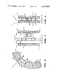
- FIG. 2 is a partial plan view of a friction core member having disk wear pads mounted thereon in accordance with the teaching of this invention
- FIG. 3 is a cross-sectional elevational view of the assembly comprised of two friction pads and a bushing member prior to being projection welded on the core member;
- FIG. 4 is an enlarged cross-sectional elevational view as taken on line 4--4 of FIG. 2 upon completion of projection welding the assembly onto the core member.
- a portion of a friction component is generally indicated by reference numeral 10 and comprises a core member 12 and plurality of attached friction pads 14.
- the core 12 is a circular disk which may be one of a plurality of such disks in a disk stack arrangement such as to effect a braking or clutching action.
- the core member 12 may be either a rotor or stator in the stack, depending on the arrangement and configuration of the total assembly comprising the brake or clutch, and this is well known and understood by those persons knowledgeable of the art.
- the pads 14 are affixed to the core 12 on both surfaces 12a and 12b thereof by fastening means 16 interconnecting two opposing pads mounted on opposite faces of the core.
- the pads are shown as having a particular configuration; however, the invention may be applied to any shape, size or configuration of friction pad which may be used in this type application.
- the pads 14 are of a cup-like configuration having a substantially flat bottom 14a and side walls 14b that may or may not be tapered inwardly toward the friction material generally indicated by reference numeral 20.
- the bottom surface of the pad 14 may include means such as depressions 14c that serve as antirotational devices which engage holes or recesses in the core surface when the pad is mounted thereon.
- the core member 12 is provided with a plurality of holes 12c therethrough which receives the pad mounting means 16 therein.
- a bushing member 30 is provided to be positioned within the access hole 12c in the core member 12 for interconnecting friction pads 14 placed on opposing surfaces 12a, 12b of the core.
- the bushing 30 is a cylindrical shaped steel piece having an O.D. that substantially corresponds to the I.D. of the access hole 12c within the core.
- the bushing 30 is characterized by annular projections 32, 34 on the ends thereof that have a substantially triangular cross-section as shown in FIG. 3 and the overall length of the bushing when placed in the access hole 12c is slightly greater by the height of the projections 32, 34 than the bore length of the hole 12c.
- the assembly pads and bushing are integrally welded together at the interface of the bushing projections 32, 34 and the bottoms of the two opposing pads.
- the bushing may be made of any wall thickness but a diameter-to-wall thickness ratio of at least 3:1 provides a suitable stable connection between welded pads. Also, for friction pads having larger surface areas, the diameter of the bushing may be increased to provide a proper base support connection when mounted on the core member and in this case the bushing diameter-to-wall thickness ratio may be increased.
Landscapes
- Engineering & Computer Science (AREA)
- General Engineering & Computer Science (AREA)
- Mechanical Engineering (AREA)
- Braking Arrangements (AREA)
- Mechanical Operated Clutches (AREA)
Priority Applications (6)
| Application Number | Priority Date | Filing Date | Title |
|---|---|---|---|
| US06/015,260 US4276969A (en) | 1979-04-02 | 1979-04-02 | Method and means for fastening friction wear pads |
| CA000345550A CA1137886A (en) | 1979-04-02 | 1980-02-11 | Method and means for fastening friction wear pads |
| GB8005952A GB2045878B (en) | 1979-04-02 | 1980-02-21 | Method and means for fastening friction pads |
| IT20166/80A IT1141240B (it) | 1979-04-02 | 1980-02-25 | Procedimento e dispositivo per fissare pastiglie d'usura ad attrito |
| FR8004043A FR2453319B1 (fr) | 1979-04-02 | 1980-02-25 | Element de friction, notamment pour freins a disques, embrayages ou analogues, et son procede de fabrication |
| JP2232880A JPS55132429A (en) | 1979-04-02 | 1980-02-26 | Fitting method and device of abrasionnproof pad |
Applications Claiming Priority (1)
| Application Number | Priority Date | Filing Date | Title |
|---|---|---|---|
| US06/015,260 US4276969A (en) | 1979-04-02 | 1979-04-02 | Method and means for fastening friction wear pads |
Publications (1)
| Publication Number | Publication Date |
|---|---|
| US4276969A true US4276969A (en) | 1981-07-07 |
Family
ID=21770401
Family Applications (1)
| Application Number | Title | Priority Date | Filing Date |
|---|---|---|---|
| US06/015,260 Expired - Lifetime US4276969A (en) | 1979-04-02 | 1979-04-02 | Method and means for fastening friction wear pads |
Country Status (6)
| Country | Link |
|---|---|
| US (1) | US4276969A (2) |
| JP (1) | JPS55132429A (2) |
| CA (1) | CA1137886A (2) |
| FR (1) | FR2453319B1 (2) |
| GB (1) | GB2045878B (2) |
| IT (1) | IT1141240B (2) |
Cited By (18)
| Publication number | Priority date | Publication date | Assignee | Title |
|---|---|---|---|---|
| US5123514A (en) * | 1991-09-20 | 1992-06-23 | Echlin Inc. | Clutch or brake system for a heavy duty vehicle |
| US5355986A (en) * | 1993-05-27 | 1994-10-18 | Prattville Manufacturing, Inc. | Clutch and disc brake friction assembly |
| US5485899A (en) * | 1991-08-08 | 1996-01-23 | Itt Automotive Europe Gmbh | Floating-frame spot-type disc brake for high-torque automotive vehicles |
| US6119827A (en) * | 1997-06-12 | 2000-09-19 | Daimlerchrysler Ag | Brake rotor for a motor vehicle |
| US6186287B1 (en) * | 1995-02-22 | 2001-02-13 | Power Transmission Technology, Inc. | Caliper disk brake for steel mill cranes |
| US6902044B2 (en) * | 2002-10-15 | 2005-06-07 | Arvinmeritor Technology, Llc | Disc pad assembly without backing plate |
| US20060016646A1 (en) * | 2004-07-22 | 2006-01-26 | Banks Daniel E | Disc brake rotor assembly with replaceable wear surfaces |
| US20080173517A1 (en) * | 2007-01-19 | 2008-07-24 | Nsk-Warner Kabushiki Kaisha | Friction plate for wet multi-plate clutch |
| US20120111674A1 (en) * | 2010-11-08 | 2012-05-10 | Ashima Ltd. | Wear-resistant brake disc |
| TWI398373B (zh) * | 2010-11-10 | 2013-06-11 | Ashima Ltd | Wear discs |
| US20130309520A1 (en) * | 2012-05-17 | 2013-11-21 | GM Global Technology Operations LLC | Method of bonding panels of dissimilar material and bonded structure |
| US20140144747A1 (en) * | 2012-11-27 | 2014-05-29 | Schaeffler Technologies AG & Co. KG | Friction plate having mechanically connected friction material |
| CN108561460A (zh) * | 2018-06-07 | 2018-09-21 | 北京天宜上佳高新材料股份有限公司 | 一种组合式制动盘及制动装置 |
| CN109386561A (zh) * | 2017-08-03 | 2019-02-26 | 米巴摩擦技术有限公司 | 用于制造摩擦元件的方法以及摩擦元件 |
| US10274034B2 (en) * | 2017-07-12 | 2019-04-30 | Goodrich Corporation | Wear liner with integrated torque button |
| CN112178092A (zh) * | 2019-07-03 | 2021-01-05 | 霍尼韦尔国际公司 | 制动盘组件 |
| US10941823B2 (en) | 2017-11-27 | 2021-03-09 | Goodrich Corporation | Segmented wear liner |
| EP4553334A1 (en) * | 2023-11-10 | 2025-05-14 | Goodrich Corporation | A friction disk comprising a washer for improved riveting of wear liners |
Families Citing this family (4)
| Publication number | Priority date | Publication date | Assignee | Title |
|---|---|---|---|---|
| US4858742A (en) * | 1988-05-13 | 1989-08-22 | Dana Corproation | Clutch disk with cushioned friction element assembly |
| US5558186A (en) * | 1995-05-24 | 1996-09-24 | The Bfgoodrich Company | Friction disk with renewable wear faces |
| US5779006A (en) * | 1995-05-24 | 1998-07-14 | The B. F. Goodrich Company | Composite friction disk having replaceable wear faces |
| JP5128654B2 (ja) * | 2010-12-07 | 2013-01-23 | 曙ブレーキ工業株式会社 | ディスクブレーキ用摩擦材組立体 |
Citations (4)
| Publication number | Priority date | Publication date | Assignee | Title |
|---|---|---|---|---|
| US1039137A (en) * | 1912-04-04 | 1912-09-24 | Albert L Johnson | Process of electric welding. |
| US3064782A (en) * | 1958-12-15 | 1962-11-20 | Bendix Corp | Lining button-spring loaded |
| US3710914A (en) * | 1971-12-18 | 1973-01-16 | Friction Prod Co | Rivetless friction pad for aircraft brakes |
| US3913716A (en) * | 1974-04-04 | 1975-10-21 | Abex Corp | Welded friction article and method of assembly |
Family Cites Families (2)
| Publication number | Priority date | Publication date | Assignee | Title |
|---|---|---|---|---|
| GB940593A (en) * | 1960-10-20 | 1963-10-30 | G K N Screws And Fasteners Ltd | Improvements relating to weld nuts |
| US3114030A (en) * | 1961-07-10 | 1963-12-10 | Ruskin Dev & Mfg Corp | Resistance welding |
-
1979
- 1979-04-02 US US06/015,260 patent/US4276969A/en not_active Expired - Lifetime
-
1980
- 1980-02-11 CA CA000345550A patent/CA1137886A/en not_active Expired
- 1980-02-21 GB GB8005952A patent/GB2045878B/en not_active Expired
- 1980-02-25 IT IT20166/80A patent/IT1141240B/it active
- 1980-02-25 FR FR8004043A patent/FR2453319B1/fr not_active Expired
- 1980-02-26 JP JP2232880A patent/JPS55132429A/ja active Granted
Patent Citations (4)
| Publication number | Priority date | Publication date | Assignee | Title |
|---|---|---|---|---|
| US1039137A (en) * | 1912-04-04 | 1912-09-24 | Albert L Johnson | Process of electric welding. |
| US3064782A (en) * | 1958-12-15 | 1962-11-20 | Bendix Corp | Lining button-spring loaded |
| US3710914A (en) * | 1971-12-18 | 1973-01-16 | Friction Prod Co | Rivetless friction pad for aircraft brakes |
| US3913716A (en) * | 1974-04-04 | 1975-10-21 | Abex Corp | Welded friction article and method of assembly |
Cited By (23)
| Publication number | Priority date | Publication date | Assignee | Title |
|---|---|---|---|---|
| US5485899A (en) * | 1991-08-08 | 1996-01-23 | Itt Automotive Europe Gmbh | Floating-frame spot-type disc brake for high-torque automotive vehicles |
| US5123514A (en) * | 1991-09-20 | 1992-06-23 | Echlin Inc. | Clutch or brake system for a heavy duty vehicle |
| US5355986A (en) * | 1993-05-27 | 1994-10-18 | Prattville Manufacturing, Inc. | Clutch and disc brake friction assembly |
| US6186287B1 (en) * | 1995-02-22 | 2001-02-13 | Power Transmission Technology, Inc. | Caliper disk brake for steel mill cranes |
| US6119827A (en) * | 1997-06-12 | 2000-09-19 | Daimlerchrysler Ag | Brake rotor for a motor vehicle |
| US6902044B2 (en) * | 2002-10-15 | 2005-06-07 | Arvinmeritor Technology, Llc | Disc pad assembly without backing plate |
| US20060016646A1 (en) * | 2004-07-22 | 2006-01-26 | Banks Daniel E | Disc brake rotor assembly with replaceable wear surfaces |
| US7159698B2 (en) * | 2004-07-22 | 2007-01-09 | Bendix Spicer Foundation Brake, Llc | Disc brake rotor assembly with replaceable wear surfaces |
| US20080173517A1 (en) * | 2007-01-19 | 2008-07-24 | Nsk-Warner Kabushiki Kaisha | Friction plate for wet multi-plate clutch |
| US20120111674A1 (en) * | 2010-11-08 | 2012-05-10 | Ashima Ltd. | Wear-resistant brake disc |
| TWI398373B (zh) * | 2010-11-10 | 2013-06-11 | Ashima Ltd | Wear discs |
| US20130309520A1 (en) * | 2012-05-17 | 2013-11-21 | GM Global Technology Operations LLC | Method of bonding panels of dissimilar material and bonded structure |
| US9012029B2 (en) * | 2012-05-17 | 2015-04-21 | GM Global Technology Operations LLC | Method of bonding panels of dissimilar material and bonded structure |
| US20140144747A1 (en) * | 2012-11-27 | 2014-05-29 | Schaeffler Technologies AG & Co. KG | Friction plate having mechanically connected friction material |
| US10274034B2 (en) * | 2017-07-12 | 2019-04-30 | Goodrich Corporation | Wear liner with integrated torque button |
| CN109386561A (zh) * | 2017-08-03 | 2019-02-26 | 米巴摩擦技术有限公司 | 用于制造摩擦元件的方法以及摩擦元件 |
| CN109386561B (zh) * | 2017-08-03 | 2020-09-04 | 米巴摩擦技术有限公司 | 用于制造摩擦元件的方法以及摩擦元件 |
| US10941823B2 (en) | 2017-11-27 | 2021-03-09 | Goodrich Corporation | Segmented wear liner |
| CN108561460A (zh) * | 2018-06-07 | 2018-09-21 | 北京天宜上佳高新材料股份有限公司 | 一种组合式制动盘及制动装置 |
| CN108561460B (zh) * | 2018-06-07 | 2024-02-20 | 北京天宜上佳高新材料股份有限公司 | 一种组合式制动盘及制动装置 |
| CN112178092A (zh) * | 2019-07-03 | 2021-01-05 | 霍尼韦尔国际公司 | 制动盘组件 |
| EP4553334A1 (en) * | 2023-11-10 | 2025-05-14 | Goodrich Corporation | A friction disk comprising a washer for improved riveting of wear liners |
| US20250154997A1 (en) * | 2023-11-10 | 2025-05-15 | Goodrich Corporation | Washer for improved riveting of carbon wear liners to ceramic matrix composite (cmc) cores |
Also Published As
| Publication number | Publication date |
|---|---|
| JPH0127288B2 (2) | 1989-05-29 |
| IT8020166A0 (it) | 1980-02-25 |
| CA1137886A (en) | 1982-12-21 |
| FR2453319B1 (fr) | 1985-12-27 |
| GB2045878B (en) | 1983-03-30 |
| IT1141240B (it) | 1986-10-01 |
| FR2453319A1 (fr) | 1980-10-31 |
| GB2045878A (en) | 1980-11-05 |
| JPS55132429A (en) | 1980-10-15 |
Similar Documents
| Publication | Publication Date | Title |
|---|---|---|
| US4276969A (en) | Method and means for fastening friction wear pads | |
| US4603760A (en) | Slotted insulator and disc brake assembly using same | |
| US4130325A (en) | Thrust plate for the bearing pins of a trunnion in a universal joint | |
| US4076106A (en) | Snap fasteners for brake disk wear plates | |
| EP0324272B1 (en) | Connector for optical fiber ribbon and a method of attaching the same | |
| US3920108A (en) | Friction disc member for brake or clutch | |
| US4083434A (en) | Brake disc with anti-oxidation peripheral covering | |
| KR102616322B1 (ko) | 브레이크 디스크 및 브레이크 디스크의 제조 방법 | |
| US3209876A (en) | Friction producing device | |
| US4643277A (en) | Brake shoe arrangement and a method of manufacturing a brake shoe | |
| EP0779445A1 (en) | Brake lining with resin-impregnated chalk inserts | |
| US2835367A (en) | Friction button and securing means therefor | |
| US20020166843A1 (en) | Method for electrical resistance welding thin metal sheets together for automotive vehicle structures | |
| US4860872A (en) | Friction disc assembly | |
| US2916123A (en) | Clutch element with ceramic-metallic friction disc | |
| EP3875798B1 (en) | Shim, shim mounting method, and pad assembly for disc brake | |
| EP2023002B2 (en) | Pad for disk brake | |
| GB2119462A (en) | Friction wear pad and method and means for fastening said pad to a disc core member | |
| KR900001737B1 (ko) | 클러치 디스크 에셈브리에 있어서의 후릭션 페이싱의 고정방법 | |
| US4846329A (en) | Friction element for clutch | |
| US1876811A (en) | Manufacture of brake shoes | |
| US2908310A (en) | Weld nut with welding projections having transversely and longitudinally curved surfaces | |
| JPS61266838A (ja) | ブレ−キ用摩擦パツドの製造方法 | |
| JPS6288823A (ja) | アスベストを含まないクラツチプレ−トアセンブリ | |
| JPH0158373B2 (2) |
Legal Events
| Date | Code | Title | Description |
|---|---|---|---|
| AS | Assignment |
Owner name: GOODYEAR AEROSPACE CORPORATION, 1210 MASSILLON RD. Free format text: ASSIGNMENT OF ASSIGNORS INTEREST.;ASSIGNORS:CHIN ROBERT W.;KRAUSE WALTER J.;REEL/FRAME:003841/0085 Effective date: 19790221 |
|
| STCF | Information on status: patent grant |
Free format text: PATENTED CASE |
|
| AS | Assignment |
Owner name: LORAL CORPORATION, 600 THIRD AVENUE, NEW YORK, NEW Free format text: ASSIGNMENT OF ASSIGNORS INTEREST.;ASSIGNOR:GOODYEAR AEROSPACE CORPORATION;REEL/FRAME:004869/0160 Effective date: 19871218 Owner name: LORAL CORPORATION,NEW YORK Free format text: ASSIGNMENT OF ASSIGNORS INTEREST;ASSIGNOR:GOODYEAR AEROSPACE CORPORATION;REEL/FRAME:004869/0160 Effective date: 19871218 |
|
| AS | Assignment |
Owner name: MANUFACTURERS HANOVER TRUST COMPANY, AS AGENT Free format text: SECURITY INTEREST;ASSIGNOR:AIRCRAFT BRAKING CORPORATION;REEL/FRAME:005164/0047 Effective date: 19890427 |
|
| AS | Assignment |
Owner name: MANUFACTURERS HANOVER TRUST COMPANY, AS AGENT Free format text: SECURITY INTEREST;ASSIGNOR:AIRCRAFT BRAKING CORPORATION, A CORP. OF DE;REEL/FRAME:005249/0786 Effective date: 19890427 |