US427209A - willis - Google Patents
willis Download PDFInfo
- Publication number
- US427209A US427209A US427209DA US427209A US 427209 A US427209 A US 427209A US 427209D A US427209D A US 427209DA US 427209 A US427209 A US 427209A
- Authority
- US
- United States
- Prior art keywords
- pneumatic
- valve
- wind
- escape
- supply
- Prior art date
- Legal status (The legal status is an assumption and is not a legal conclusion. Google has not performed a legal analysis and makes no representation as to the accuracy of the status listed.)
- Expired - Lifetime
Links
- 210000000056 organs Anatomy 0.000 description 20
- 238000007906 compression Methods 0.000 description 6
- 230000000875 corresponding Effects 0.000 description 6
- 230000001808 coupling Effects 0.000 description 4
- 238000010168 coupling process Methods 0.000 description 4
- 238000005859 coupling reaction Methods 0.000 description 4
- 230000000977 initiatory Effects 0.000 description 4
- 102100005327 ASIP Human genes 0.000 description 2
- 101700085779 ASIP Proteins 0.000 description 2
- 230000005540 biological transmission Effects 0.000 description 2
- 230000001276 controlling effect Effects 0.000 description 2
- 238000007599 discharging Methods 0.000 description 2
- 230000000694 effects Effects 0.000 description 2
- 230000004048 modification Effects 0.000 description 2
- 238000006011 modification reaction Methods 0.000 description 2
Images


Classifications
-
- G—PHYSICS
- G10—MUSICAL INSTRUMENTS; ACOUSTICS
- G10B—ORGANS, HARMONIUMS OR SIMILAR WIND MUSICAL INSTRUMENTS WITH ASSOCIATED BLOWING APPARATUS
- G10B3/00—Details or accessories
- G10B3/06—Valves; Sleeves
Definitions
- the obj eet of this invention is to quicken the repetition-action of pneumatic levers of organs, and thus to enable the organist to play, for example, rapid passages with great facility.
- the rapid transmission of motion from the keys for sounding musical notes has already been effected by mechanical means in a patent granted to me April 6, 1886, No. 339,608; but in order to enable me do this at a greater distance than heretofore without effecting the rapid repetition of the same notes I use an arrangement of pneumatic apparatus which enables me to insure an instantaneous escape of the wind on the termination of the action.
- My invention it may be remarked, has a general application where pneumatic energy is required, whether it be for the coupling of various organs together or for coupling together several stops of a pedal or other organ, or for effecting mechanical movements, such as the drawing or withdrawing of stops.
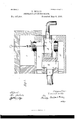
- Figure 1 shows in sectional elevation my novel arrangement for securing the independent action of the supply and escape valves of a pneumatic lever.
- Fig. 2 shows the mechanism which may be used for transmitting the movement of a key or pedal for putting into action the pneumatic lever for reiterating the sound of an organ-pipe.
- Fig. 3 shows a modification of the wind-passages required for bringing two or more pneumatic levers into connection with one pair of the supply and exhaust valves.
- FIG. l A is a closed chamberinto which wind is admitted on the depression of a key or pedal for initiating the action of the apparatus.
- a convenient means for admitting wind to this chamber A is shown in Fig. 2, where Cb is a pipe connecting the chamber A with a passage B in the bottom of the windchest 1.
- Z) Z) are supply and escape valves carried by a stem b the one having its seat in the wind-chest and the other outside the windchest.
- the pendent end of this rod 11 is e011- nected to an elastic arm b fixed to the under side of the wind-chest 1, and situate between the elastic arm and the bottom of the wind-chest is an electro-magnet b, which on the depression of a key or pedal that then closes an electric circuit becomes magnetized and serves to lift the arm b close the escape-valve Z), and open the supply valve Z).
- IVind from the wind-chest 1 will then pass by the passage B, through the pipe a, to the chamber A, for the purpose to be presently explained, and on the release of the key or pedal the wind will leave the chamber A and escape to the atmosphere by the valve Z).
- the closed chamber A is fitted with two disk pneumatic levers C C.
- the disk lever C carries a valve 0, which has its seat in a second wind-chest 2, such wind-chest serving to supply wind to the pneumatic lever D by a passage (Z, which pneumatic lever may be assumed to control the utterances of the organ-pipe with which it is in connection or effect some other desired operation in the organ for which it is applicable.
- the disk lever C carries a valve 0 for closing the escape-passage cl from the pneumatic lover I).
- the action of the apparatus is as follows: Supposing that it is desired to sound any given note, the pneumatic lever corresponding to that pipe is set in action, as heretofore, on depression of the corresponding key or pedal, and the pipe continues to sound until the performer permits the key or pedal to rise.
- the depression of this key or pedal by opening the valve 1), Fig. 2, in the wind-chest 1 and closing its corresponding escape-valve 1) causes a compression of the air in the chamher A, as already explained, thereby holding the escape-valve c firmly to its seat, while at the same instant it lifts the supply-valve 0, connected with the disk pneumatic lever O, and inflates the pneumatic lever D through the passage d.
- I may find it desirable to provide an automatic inlet-valve inor near the chamber for the admission of air to compensate for the sudden movement of the column of air in the passage a.
- I To provide for operating two or more pneumatic levers by means of one pair of valves arranged as shown in Fig. 1, I connect the group of pneumatic levers intended to be so actuated with one and the same air-supply pipe or passage.
- This air-supply passage I put in communication with both the supply and exhaust valves,as illustrated at Fig. 3, where, as in Fig. l, 0 represents the supplyvalve, and c the escape-valve.
- Fig. 8E is a channel or cross-passage connecting the airsupply passage (1 with the exhaust-passage d
- c is a pipe connecting the channel E by means of branches (not shown in the drawings) with the several pneumatic levers intended to be operated by means of my invention.
- the supply-valve 0 On the depression, therefore, of a key or pedal, and the admission thereby of air to the chamber A, the supply-valve 0 will rise and deliver wind through the passages cl E c, &c., to the various pneumatic levers in connection with the supply-pipe e, or such of them as answer to the drawn steps of the portion of the organ to which the group of pneumatic levers belongs.
- the supply of Wind On the release of the key the supply of Wind will be cut off and all the pneumatic levers which have been operated through the rise of the valve 0 will exhaust through the pipe c, channel E, passage d, and the exhaust-valve c.
- a further advantage resulting from the use of my invention is that the actions of the supply and escape valves are automatically limited to the exact requirements of the pneumatic lever.
Description
(N0 MOdeI.) 3 Sheets-Sheet 1.
v. WILLIS. PNEUMATIC ACTION FOR ORGANS.
No. 427.209. Patented Ma 6 1890.
(No Model.) 3 Sheets-Sheet 2.
. V. WI
PNEUMATIC AGTI RGANS.
No. 427,209. atented May 6, 1890 a? b lhve zjqr; wkzzs,
v v i i y (No Model.) 3 Sheets-Sheet 3 v. WILLIS. PNEUMATIC ACTION FOR ORGANS.
No. 427,209. Patented May 6, 1890.
UNITED STATES PATENT @EEICE.
VINCENT \VILLIS, OF CAMDEN-TO'WN, COUNTY OF MIDDIJESEX, ENGLAND.
PNEUMATIC ACTION FOR ORGANS.
SPECIFICATION forming part of Letters Patent No. 427,209, dated May 6, 1890.
Application filed December 12, 1889. Serial No.333,527. (N0 model.)
To all whom it may concern.-
Be it known that I, VINCENT WILLIs, of 9 Rochester Terrace, Camden Town, in the county of MiddleseX, England, have invented certain new and useful Improvements in Means for Controlling the Valves of Pneumatic Levers of Organs, of which the follow ing is a specification.
The obj eet of this invention is to quicken the repetition-action of pneumatic levers of organs, and thus to enable the organist to play, for example, rapid passages with great facility. The rapid transmission of motion from the keys for sounding musical notes has already been effected by mechanical means in a patent granted to me April 6, 1886, No. 339,608; but in order to enable me do this at a greater distance than heretofore without effecting the rapid repetition of the same notes I use an arrangement of pneumatic apparatus which enables me to insure an instantaneous escape of the wind on the termination of the action.
In order to illustrate my invention, I have shown in the accompanying drawings the apparatus which I employ for supplying the pneumatic levers with wind and discharging the wind therefrom to produce a rapid repetition of sound, and I have also shown an efficient means-such as that already applied to 0rgansfor setting in action the novel apparatus which forms the subject of the present invention.
My invention, it may be remarked, has a general application where pneumatic energy is required, whether it be for the coupling of various organs together or for coupling together several stops of a pedal or other organ, or for effecting mechanical movements, such as the drawing or withdrawing of stops.
In the accompanying drawings, Figure 1 shows in sectional elevation my novel arrangement for securing the independent action of the supply and escape valves of a pneumatic lever. Fig. 2 shows the mechanism which may be used for transmitting the movement of a key or pedal for putting into action the pneumatic lever for reiterating the sound of an organ-pipe. Fig. 3 shows a modification of the wind-passages required for bringing two or more pneumatic levers into connection with one pair of the supply and exhaust valves.
In Fig. l, A is a closed chamberinto which wind is admitted on the depression of a key or pedal for initiating the action of the apparatus. A convenient means for admitting wind to this chamber A is shown in Fig. 2, where Cb is a pipe connecting the chamber A with a passage B in the bottom of the windchest 1.
Z) Z) are supply and escape valves carried by a stem b the one having its seat in the wind-chest and the other outside the windchest. The pendent end of this rod 11 is e011- nected to an elastic arm b fixed to the under side of the wind-chest 1, and situate between the elastic arm and the bottom of the wind-chest is an electro-magnet b, which on the depression of a key or pedal that then closes an electric circuit becomes magnetized and serves to lift the arm b close the escape-valve Z), and open the supply valve Z). IVind from the wind-chest 1 will then pass by the passage B, through the pipe a, to the chamber A, for the purpose to be presently explained, and on the release of the key or pedal the wind will leave the chamber A and escape to the atmosphere by the valve Z).
' The closed chamber A is fitted with two disk pneumatic levers C C. The disk lever C carries a valve 0, which has its seat in a second wind-chest 2, such wind-chest serving to supply wind to the pneumatic lever D by a passage (Z, which pneumatic lever may be assumed to control the utterances of the organ-pipe with which it is in connection or effect some other desired operation in the organ for which it is applicable. The disk lever C carries a valve 0 for closing the escape-passage cl from the pneumatic lover I).
The action of the apparatus is as follows: Supposing that it is desired to sound any given note, the pneumatic lever corresponding to that pipe is set in action, as heretofore, on depression of the corresponding key or pedal, and the pipe continues to sound until the performer permits the key or pedal to rise. The depression of this key or pedal by opening the valve 1), Fig. 2, in the wind-chest 1 and closing its corresponding escape-valve 1) causes a compression of the air in the chamher A, as already explained, thereby holding the escape-valve c firmly to its seat, while at the same instant it lifts the supply-valve 0, connected with the disk pneumatic lever O, and inflates the pneumatic lever D through the passage d. WVhen the pneumatic leverD is inflated,the compression is practically equal on both sides of the disk pneumatic lever O, and the supply-valve c, losing its support, falls nearly down to its seat. Whilethe apparatus is in this condition, the note affected by the pneumatic lever D will continue to sound. Upon allowing the key or pedal to rise compression instantly ceases in the chamber, and the valve 0, being now actually closed by a double influenceviz., the pressure 011 the valve itself by the air in the wind-chest 2 and by the pressure of the wind on the upper surface of the disk pneumatic lever Otl1e compressed air which had inflated the pneumatic lever D is instantly expressed through the escape-valve c by the resistance it had previously overcome, and the pneumatic lever D returns instantly to its normal or qui escent position.
To avoid back action in the'chamber A, which is liable to occur when the passage a is of great length, I may find it desirable to provide an automatic inlet-valve inor near the chamber for the admission of air to compensate for the sudden movement of the column of air in the passage a.
To provide for operating two or more pneumatic levers by means of one pair of valves arranged as shown in Fig. 1, I connect the group of pneumatic levers intended to be so actuated with one and the same air-supply pipe or passage. This air-supply passage I put in communication with both the supply and exhaust valves,as illustrated at Fig. 3, where, as in Fig. l, 0 represents the supplyvalve, and c the escape-valve. In Fig. 8,E is a channel or cross-passage connecting the airsupply passage (1 with the exhaust-passage d, and c is a pipe connecting the channel E by means of branches (not shown in the drawings) with the several pneumatic levers intended to be operated by means of my invention. On the depression, therefore, of a key or pedal, and the admission thereby of air to the chamber A, the supply-valve 0 will rise and deliver wind through the passages cl E c, &c., to the various pneumatic levers in connection with the supply-pipe e, or such of them as answer to the drawn steps of the portion of the organ to which the group of pneumatic levers belongs. On the release of the key the supply of Wind will be cut off and all the pneumatic levers which have been operated through the rise of the valve 0 will exhaust through the pipe c, channel E, passage d, and the exhaust-valve c.
Should it be desired to use an exhaust instead of a plenum of air for working the pneumatic levers according to my invention, it will only be necessary to invert the apparatus shown in Fig. 1 and to reverse the position, with respect to their seats, of the supply and exhaust valves.
From the above description it will be understood that provision is made both for the instantaneous action of the escape-valve unhindered or unretarded by an open supplyvalve and for the instantaneous inflation of the pneumatic lever unhindered by an open escape-valve, the valves initiating the movement counting for nothingby reason of their minuteness.
A further advantage resulting from the use of my invention is that the actions of the supply and escape valves are automatically limited to the exact requirements of the pneumatic lever.
Having now particularly described and ascertained the nature of my said invention and in what manner the same is to be performed, I declare that what I claim is In an organ provided with pneumatic levers for transmitting motion derived from the keys, pedals, knobs, or draw-stops, an air-chamber alternately in communication with a windchest and the atmosphere, fitted with a pair of disk pneumatic levers, the one having attached to it a supply-valve working in a windchest in connection with the pneumatic lever to be operated and the other an escape-valve opening to the atmosphere and closing the vent of the pneumatic lever, such valves acting independently the one of the other when wind is admitted to the air-chamber or allowed to escape therefrom, as and for the purpose above set forth.
VINCENT VILLIS.
WVitnesses:
H. K. WHITE, A. XV. SPAOKMAN.
Publications (1)
| Publication Number | Publication Date |
|---|---|
| US427209A true US427209A (en) | 1890-05-06 |
Family
ID=2496119
Family Applications (1)
| Application Number | Title | Priority Date | Filing Date |
|---|---|---|---|
| US427209D Expired - Lifetime US427209A (en) | willis |
Country Status (1)
| Country | Link |
|---|---|
| US (1) | US427209A (en) |
-
0
- US US427209D patent/US427209A/en not_active Expired - Lifetime
Similar Documents
| Publication | Publication Date | Title |
|---|---|---|
| US427209A (en) | willis | |
| US336351A (en) | Hilbokne l | |
| US760115A (en) | Pneumatic-coupler for pipe or reed organs. | |
| US1078852A (en) | Organ-coupler. | |
| US323829A (en) | roosevelt | |
| US1081703A (en) | Musical instrument. | |
| US1035738A (en) | Reed-organ. | |
| US1471318A (en) | Expressive-touch action for organs and the like instruments | |
| US572129A (en) | Organ | |
| US1195536A (en) | Fobnia | |
| US1075313A (en) | Self-playing musical instrument. | |
| US759338A (en) | Pipe-organ. | |
| US353894A (en) | Pneumatic action for musical instruments | |
| US566150A (en) | ehrlich | |
| US122777A (en) | Improvement in organ actions | |
| USRE9218E (en) | Best available copy | |
| US639477A (en) | Pneumatic valve-action. | |
| US856774A (en) | Pneumatic self-playing musical instrument. | |
| US416974A (en) | Pneumatic action for pipe-organs | |
| US1080595A (en) | Automatic playing instrument. | |
| US797182A (en) | Tone-expression-controlling device for mechanical musical instruments. | |
| US368165A (en) | parker | |
| US1000594A (en) | Tone-modulator for pneumatically-operated musical instruments. | |
| US879738A (en) | Bellows for automatic musical instruments. | |
| US343900A (en) | gally |