US4193045A - Temperature compensated surface acoustic wave oscillators - Google Patents
Temperature compensated surface acoustic wave oscillators Download PDFInfo
- Publication number
- US4193045A US4193045A US05/907,556 US90755678A US4193045A US 4193045 A US4193045 A US 4193045A US 90755678 A US90755678 A US 90755678A US 4193045 A US4193045 A US 4193045A
- Authority
- US
- United States
- Prior art keywords
- surface acoustic
- acoustic wave
- resonators
- wave oscillator
- sub
- Prior art date
- Legal status (The legal status is an assumption and is not a legal conclusion. Google has not performed a legal analysis and makes no representation as to the accuracy of the status listed.)
- Expired - Lifetime
Links
Images


Classifications
-
- H—ELECTRICITY
- H03—ELECTRONIC CIRCUITRY
- H03H—IMPEDANCE NETWORKS, e.g. RESONANT CIRCUITS; RESONATORS
- H03H9/00—Networks comprising electromechanical or electro-acoustic elements; Electromechanical resonators
- H03H9/02—Details
- H03H9/125—Driving means, e.g. electrodes, coils
- H03H9/145—Driving means, e.g. electrodes, coils for networks using surface acoustic waves
- H03H9/14544—Transducers of particular shape or position
- H03H9/14594—Plan-rotated or plan-tilted transducers
-
- H—ELECTRICITY
- H03—ELECTRONIC CIRCUITRY
- H03B—GENERATION OF OSCILLATIONS, DIRECTLY OR BY FREQUENCY-CHANGING, BY CIRCUITS EMPLOYING ACTIVE ELEMENTS WHICH OPERATE IN A NON-SWITCHING MANNER; GENERATION OF NOISE BY SUCH CIRCUITS
- H03B5/00—Generation of oscillations using amplifier with regenerative feedback from output to input
- H03B5/30—Generation of oscillations using amplifier with regenerative feedback from output to input with frequency-determining element being electromechanical resonator
- H03B5/32—Generation of oscillations using amplifier with regenerative feedback from output to input with frequency-determining element being electromechanical resonator being a piezoelectric resonator
- H03B5/326—Generation of oscillations using amplifier with regenerative feedback from output to input with frequency-determining element being electromechanical resonator being a piezoelectric resonator the resonator being an acoustic wave device, e.g. SAW or BAW device
-
- H—ELECTRICITY
- H03—ELECTRONIC CIRCUITRY
- H03H—IMPEDANCE NETWORKS, e.g. RESONANT CIRCUITS; RESONATORS
- H03H3/00—Apparatus or processes specially adapted for the manufacture of impedance networks, resonating circuits, resonators
- H03H3/007—Apparatus or processes specially adapted for the manufacture of impedance networks, resonating circuits, resonators for the manufacture of electromechanical resonators or networks
- H03H3/08—Apparatus or processes specially adapted for the manufacture of impedance networks, resonating circuits, resonators for the manufacture of electromechanical resonators or networks for the manufacture of resonators or networks using surface acoustic waves
- H03H3/10—Apparatus or processes specially adapted for the manufacture of impedance networks, resonating circuits, resonators for the manufacture of electromechanical resonators or networks for the manufacture of resonators or networks using surface acoustic waves for obtaining desired frequency or temperature coefficient
-
- H—ELECTRICITY
- H03—ELECTRONIC CIRCUITRY
- H03H—IMPEDANCE NETWORKS, e.g. RESONANT CIRCUITS; RESONATORS
- H03H9/00—Networks comprising electromechanical or electro-acoustic elements; Electromechanical resonators
- H03H9/02—Details
- H03H9/02535—Details of surface acoustic wave devices
- H03H9/02818—Means for compensation or elimination of undesirable effects
- H03H9/02834—Means for compensation or elimination of undesirable effects of temperature influence
-
- H—ELECTRICITY
- H03—ELECTRONIC CIRCUITRY
- H03H—IMPEDANCE NETWORKS, e.g. RESONANT CIRCUITS; RESONATORS
- H03H9/00—Networks comprising electromechanical or electro-acoustic elements; Electromechanical resonators
- H03H9/02—Details
- H03H9/125—Driving means, e.g. electrodes, coils
- H03H9/145—Driving means, e.g. electrodes, coils for networks using surface acoustic waves
- H03H9/14544—Transducers of particular shape or position
- H03H9/1455—Transducers of particular shape or position constituted of N parallel or series transducers
-
- H—ELECTRICITY
- H03—ELECTRONIC CIRCUITRY
- H03H—IMPEDANCE NETWORKS, e.g. RESONANT CIRCUITS; RESONATORS
- H03H9/00—Networks comprising electromechanical or electro-acoustic elements; Electromechanical resonators
- H03H9/25—Constructional features of resonators using surface acoustic waves
-
- H—ELECTRICITY
- H03—ELECTRONIC CIRCUITRY
- H03B—GENERATION OF OSCILLATIONS, DIRECTLY OR BY FREQUENCY-CHANGING, BY CIRCUITS EMPLOYING ACTIVE ELEMENTS WHICH OPERATE IN A NON-SWITCHING MANNER; GENERATION OF NOISE BY SUCH CIRCUITS
- H03B5/00—Generation of oscillations using amplifier with regenerative feedback from output to input
- H03B5/02—Details
- H03B5/04—Modifications of generator to compensate for variations in physical values, e.g. power supply, load, temperature
Definitions
- This invention relates to a surface acoustic wave (SAW) oscillator comprising a plurality of parallel-connected surface acoustic wave resonators, each of which includes a pair of interdigitated electrodes mounted on a quartz substrate for propagating a surface acoustic wave.
- SAW surface acoustic wave
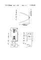
- the prior art surface acoustic wave oscillator comprises as shown in FIG. 1, an active element-containing circuit 2 which is connected to a surface acoustic wave oscillator 1 through the terminals 1a, 1b.
- a pair of interdigitated electrodes 4, 5 are mounted on the main plane of a substrate 3 prepared from, for example, quartz for connection to said active element-containing circuit 2.
- FIG. 2 shows an equivalent circuit of the surface acoustic wave oscillator of FIG. 1.
- a resonator section 1 comprises a series circuit of an inductance L and capacitor C connected in parallel to another capacitor C T .
- a circuit section 2 including an active element consists of a series circuit of a capacitor C L and negative resistor -R.
- the resonance circuit section 1 and circuit section 2 are connected by terminals 1a, 1b.
- the constants L, C, C T of the equivalent circuit can be freely selected by changing the number of the respective paired electrode elements or fingers of the interdigital electrodes, the thickness of said interdigital electrodes and the length of those portions of the respective paired electrode elements or fingers which are actually interdigitated with each other.
- the impedance z thereof generally varies with ambient temperature. This means that the surface acoustic wave oscillator has a frequency largely governed by ambient temperature.
- FIG. 3 is a curve diagram of the deviation ⁇ f of the aforesaid oscillation frequency f of the oscillator relative to ambient temperature T, where the substrate thereof is formed of quartz and the main plane of the quartz is represented by the rotated Y cut plane.
- the frequency deviation ⁇ f is substantially reduced to zero at the turnover temperature T p .
- the turnover temperature T p is shifted either upward or downward, then the frequency deviation ⁇ f increases along a second degree temperature coefficient. Compensation for the temperature dependency of oscillation frequency has hitherto been undertaken in a circuit including an active element. Yet said compensation has proved unsatisfactory.
- a crystal oscillator which has been proposed to date to compensate for the temperature dependency of oscillation frequency includes the U.S. Pat. No. 3,821,666. According to this prior art, three bulk wave crystal vibrators are connected in parallel. This parallel circuit is connected to an active element-containing circuit. Said U.S. Patent oscillator is the temperature-compensation type which is intended to reduce frequency deviation over a prescribed temperature range by connecting in parallel the three crystal vibrators which collectively display a particular frequency deviation characteristic relative to ambient temperature.
- the bulk vibrators included in a temperature compensation type oscillator present greater difficulties in manufacture, according as said oscillator is demanded to have a higher frequency.
- the reason is that a substrate of bulk wave crystal vibrator has to be made thinner in the inverse ratio to the increased frequency.
- provision of, for example, wiring supports unavoidably give rise to variations in the properties of said temperature compensation type oscillator, whose practical application is therefore undesirably limited.
- a surface acoustic wave oscillator of this invention the rotated Y cut plane of quartz is used as a substrate.
- a pair of interdigitated electrodes whose electrode elements are mounted on the main plane of the substrate in the alternately adjacent form are connected to an active-element containing circuit through connection terminals.
- the SAW resonator of this invention comprising a surface acoustic wave resonator presents a noticeable difference from the prior art bulk vibrator type oscillator in the properties resulting from the operation principle, construction and resonance condition, a plurality of surface acoustic wave resonators are connected in parallel and are so constructed that a prescribed relationship exists between the frequencies of the respective surface acoustic wave resonators as well as between the turnover temperatures.
- the technique of producing a surface acoustic wave oscillator embodying this invention has not been known to date, nor can be inferred from any prior art.
- the invention provides a surface acoustic wave oscillator which comprises a resonance circuit formed of a plurality of surface acoustic wave resonators having different oscillation frequencies and displaying different turnover temperatures on different curves denoting frequency deviations relative to ambient temperature, said each surface acoustic wave resonator being formed of a pair of interdigital electrodes whose electrode elements are mounted in the alternately adjacent form on a substrate for propagating a surface acoustic wave; and an active element-containing circuit connected to the resonance circuit, and wherein the plurality of surface acoustic wave resonators have such oscillation frequencies and turnover temperatures as meet the conditions expressed by the following formulas:
- f H a maximum frequency among those frequencies of a plurality of resonators collectively connected to the active element-containing circuit which are produced at turnover temperatures on a temperature characteristic curve.
- f L a minimum frequency among said frequencies of the plurality of resonators.
- ⁇ fa allowable frequency deviation of the surface acoustic wave oscillator.
- T p1 to T pn those turnover temperatures of the plurality of oscillators each comprising a single resonator which are indicated on a temperature characteristic curve.
- This invention has newly developed the arrangement of the plurality of surface acoustic wave resonators mounted on the surface of a quartz substrate and the construction of electrodes constituting said resonators in order to meet the requirements denoted by the above formulas, thereby providing a surface acoustic wave oscillator whose frequency varies little with ambient temperature over a broad range.
- the SAW resonator used with the respective embodiments can be constructed by the technique of photolithography to admit of tonnage production; it is unnecessary to reduce the thickness of a substrate in inverse proportion to the resonance frequency as in the case of a bulk wave crystal vibrator, thereby ensuring the easy manufacture of the SAW oscillator with high precision in the frequency range from scores of Mega Hertz (MHz) units to several Giga Hertz (GHz) units; application of printed wiring on the same substrate enables the vibrating section and substrate to be separately supported, thereby eliminating variations in the properties of the SAW oscillator; and the constant of an equivalent circuit of the SAW oscillator can be freely selected by changing the number of the respective paired electrode elements or fingers of the interdigital electrodes and the width defined between said respective paired electrode element fingers, thereby enabling temperature compensation to be effected over a substantially unlimited range.
- FIG. 1 schematically shows the arrangement of the prior art surface acoustic wave oscillator including a single surface acoustic wave resonator
- FIG. 2 is an equivalent circuit of the prior art surface acoustic wave oscillator of FIG. 1;
- FIG. 3 is a curve diagram showing the frequency deviation of the prior art surface acoustic wave oscillator of FIG. 1 relative to embodiment temperature;
- FIG. 4 schematically sets forth the arrangement of the surface acoustic wave oscillator of this invention comprising a plurality of parallel-connected surface acoustic wave resonators;
- FIG. 5 is an equivalent circuit of the surface acoustic wave oscillator of FIG. 4;
- FIG. 6 is a curve diagram of the frequency deviation relative to ambient temperature of a surface acoustic wave oscillator according to one embodiment of this invention which is formed of two parallel-connected surface acoustic wave resonators;
- FIG. 7 is a curve diagram of the frequency deviation relative to ambient temperature of a surface acoustic wave oscillator according to another embodiment of the invention which comprises three parallel-connected surface acoustic wave resonators;
- FIG. 8 schematically indicates the arrangement of two surface acoustic wave resonators according to another embodiment of the invention which are so arranged as to cause the respective surface acoustic waves to be propagated in different directions;
- FIG. 9 schematically shows the arrangement of three surface acoustic wave resonators according to still another embodiment of the invention which are so arranged as to cause the respective surface acoustic waves to be propagated in different directions;
- FIG. 10 graphically denotes relationship between propagation angles defined by different propagating direction of surface acoustic means accurring in the embodiment of FIG. 8 and different turnover temperatures on the curves showing frequency directions relative to ambient temperature;
- FIG. 11 graphically shows relationship between the angles defined by surface acoustic waves propagating in different directions over the surface of the resonators according to the embodiment of FIG. 8 and variations in the propagating velocity of said surface acoustic wave;
- FIG. 12 is an oblique view of a surface acoustic wave oscillator according to still another embodiment of the invention, in which surface acoustic wave resonators are arranged on the different main rotated Y cut planes of the quartz substrate;
- FIG. 13 graphically represents relationship between the turnover temperatures corresponding to the different rotation angles of the respective rotated Y cut planes of the quartz substrate and the propagation velocity of surface acoustic waves;
- FIG. 14 schematically shows the arrangement of two parallel connected surface acoustic wave resonators according to a further embodiment of the invention, in which the interdigitated electrodes of one of the resonators have a different thickness from those of the other;
- FIG. 15 is a cross sectional view on line XV--XV of FIG. 14;
- FIG. 16 graphically indicates relationship between the turnover temperatures corresponding to the different thickness of the aluminum electrodes of the embodiment of FIG. 14 and the propagation velocity of surface acoustic waves;
- FIG. 17 graphically shows relationship between the turnover temperatures corresponding to the different thicknesses of the gold electrodes of the embodiment of FIG. 14 and the propagation velocity of surface acoustic waves;
- FIG. 18 is a cross sectional view of the resonator section of a surface acoustic wave oscillator according to another embodiment in which the frequencies of the adjacent resonators are designed to have different degrees of temperature dependence;
- FIG. 19 is a cross sectional view of the resonator section of a surface acoustic wave oscillator according to still another embodiment in which the frequencies of the adjacent resonators are designed to have different degrees of temperature dependence.
- FIG. 4 schematically illustrates the principle by which the surface acoustic wave oscillator 1 of this invention is operated.
- a plurality of surface acoustic wave resonators M 1 to M n are connected in parallel on the main plane of a quartz substrate 3 prepared, for example, by the ST cut.
- This resonator section is connected to an active element-containing circuit 2 through terminals 1a, 1b.
- the arrangement of FIG. 4 is equivalently shown in FIG. 5.
- the respective surface acoustic wave resonators and active element-containing circuit 2 have the same arrangement as those of FIG. 2.
- the SAW resonator M 1 is indicated by a circuit formed by connecting a series circuit of an inductor L 1 and capacitor C 1 in parallel with another capacitor C T1 .
- the suffix i denotes the serial positions of the actually used SAW resonator, inductor and capacitor respectively.
- the constants L, C, C T of the equivalent circuit can be freely selected by changing the number of the respective paired electrode elements or fingers of the interdigital electrodes, the thickness of said interdigital electrodes and the length of those portions of the respective paired electrode elements or fingers which are actually interdigitated with each other.
- the surface acoustic oscillator 1 has an oscillation frequency f expressed as follows:
- the frequency of the surface acoustic wave oscillator 1 varies with the impedance of the parallel-connected resonators. If the impedance is governed by ambient temperatures, then the frequency f of said oscillator should also be affected by the ambient temperature.
- the frequency of the surface acoustic wave oscillator of this invention is represented by f i (Hz); an intermediate temperature on a curve denoting the deviation of said frequency relative to ambient temperature T is indicated by T pi ; an allowable frequency deviation is denoted by ⁇ fa.
- the plural surface acoustic wave resonators M 1 to M n of the surface acoustic wave oscillator satisfy the conditions expressed by the following formulas:
- f H a maximum frequency among those frequencies of a plurality of resonators collectively connected to the active element-containing circuit which are produced at turnover temperatures on a temperature characteristic curve.
- f L a minimum frequency among said frequencies of the plurality of resonators.
- T p1 to T pN peak temperatures on a curve denoting a frequency deviation relative to ambient temperature.
- a surface acoustic wave oscillator comprises a resonator section formed of two resonators M 1 , M 2 included in those (M 1 to M n ) shown in FIG. 4.
- the frequency deviation ⁇ f of said oscillator has such temperature dependency that as shown by the broken line curves Q 1 , Q 2 of FIG. 6, the frequency deviation ⁇ f is reduced to zero only at turnover temperatures T p1 , T p2 .
- the frequency deviation ⁇ f approximates zero, as shown by the solid line curve Q 0 of FIG.
- the surface acoustic wave oscillator of this invention indicates a smaller frequency deviation than at least the allowable frequency deviation ⁇ fa.
- the parallel-connected surface acoustic waves resonators M 1 , M 2 are considered to satisfy the condition of f 2 -f 1 ⁇ fa derived from the aforesaid formula (3) and also the condition of T p1 ⁇ T p2 resulting from the previously mentioned formula (4).
- a solid line curve Q 0 of FIG. 7 indicates the frequency deviation relative to ambient temperature of a surface acoustic wave oscillator which comprises three parallel-connected resonators M 1 , M 2 , M 3 .
- the curves Q 1 , Q 2 , Q 3 of FIG. 7 denote the temperature characteristic curves of the frequencies of the respective resonators M 1 , M 2 , M 3 when connected to an active element-containing circuit.
- the temperature characteristic curve Q 0 of the resonator frequency is more prominently improved than the temperature characteristic curves Q 1 , Q 2 , Q 3 of the frequencies of the resonators M 1 , M 2 , M 3 each comprising a single resistor.
- the three parallel-connected surface acoustic wave resonators M 1 , M 2 , M 3 are regarded to meet the condition of f 3 -f 1 ⁇ fa derived from the formula (3) and the condition of T p1 ⁇ T p2 ⁇ T p3 resulting from the formula (4).
- the surface acoustic waves delivered from the surface acoustic wave resonators M 1 , M 2 are propagated in different directions as indicated by the arrows K 1 , K 2 , and at different rates of temperature dependence. Due to the propagating in the respective directions K 1 , K 2 , the surface acoustic waves are designed to intersect each other at a prescribed angle, and the impedances Z 1 , Z 2 of the surface acoustic wave resonators M 1 , M 2 are now rendered subject to temperature dependence.
- the surface acoustic wave oscillator of the embodiment of FIG. 8 can satisfy the conditions of the formulas (3), (4). Eventually, therefore, the frequency of the surface acoustic wave oscillator of FIG. 8 is little affected by ambient temperature over a broad range.
- FIG. 9 illustrates the arrangement of a surface acoustic wave oscillator comprising three surface acoustic wave resonators M 1 , M 2 , M 3 .
- Surface acoustic waves are propagated from said oscillator in different directions, thereby attaining the same result as the embodiment of FIG. 8.
- FIG. 10 sets forth a curve plotted from experiments conducted with the embodiments of FIGS. 8 and 9.
- the curve shows the extent to which turnover temperture varies with an angle defined by the propagation direction of surface acoustic waves indicated by, for example, the arrows K 1 , K 2 .
- FIG. 11 shows a curve plotted from experiments carried out with the embodiments of FIGS. 8 and 9.
- the curve indicates the extent to which the propagation velocity of a surface acoustic wave varies with an angle defined by the directions of said propagation.
- the more broadened the angle defined by the propagation directions of a surface acoustic wave the higher the turnover temperature and the propagation velocity. Namely, where a plurality of surface acoustic wave resonators are so arranged as to cause a surface wave to be propagated over the surface of said resonators in different directions, then the conditions denoted by the formulas (3), (4) can be satisfied.
- the quartz substrate 3 has two main planes 3a, 3b formed of different rotated Y cut planes.
- a surface acoustic wave is propagated in the same direction as indicated by the arrows K 1 , K 2 over said two main planes 3a, 3b.
- FIGS. 14 and 15 a surface acoustic wave oscillator according to a further embodiment of this invention.
- Two surface acoustic wave resonators M 1 , M 2 are mounted on the same main plane formed of the ST cut plane of the quartz substrate 3.
- a surface acoustic wave is propagated over the surface of said resonators M 1 , M 2 in the same direction as indicated by the arrows K 1 , K 2 .
- the electrodes 4, 5 of one (for example, M 1 ) of said two resonators have a different thickness from the electrodes 4, 5 of the other resonator (M 2 ).
- FIG. 16 relates to the case where the two electrodes 4, 5 are made of aluminum.
- FIG. 17 relates to the case where two electrodes 4, 5 are made of gold.
- line T corresponds turnover temperature
- line V corresponds to velocity.
- both electrodes 4, 5 are prepared from gold, then, as shown in FIG. 17, the turnover temperature and surface acoustic wave propagation velocity more prominently vary than in the case of aluminium electrodes, even when the gold electrodes have the same thickness difference as the aluminium electrodes.
- the temperature dependence of the frequency of said respective resonators M 1 , M 2 can be made to vary with the electrode material thereof.
- the process of causing the frequencies of two adjacent resonators, for example, M 1 , M 2 to have different degrees of temperature dependence can be effected either by depositing, as shown in FIG. 18, on the surface of the resonator M 1 a thin insulating layer 10 having a different temperature coefficient from the substrate 3, or by providing said thin insulating layer 10, as shown in FIG. 19, between the substrate 3 on one hand and the interdigital electrodes 4, 5 on the other.
- Said thin insulating layer 10 should advisably be formed of aluminium oxide (Al 2 O 3 ) or magnesium fluoride (MgF 2 ) which admits of easy production.
- kH being the relative film thickness which is normalized according to wavelength
- a turnover temperature can be reduced to about 80° C. which appears on a temperature dependence characteristic curve of the frequencies of SAW oscillators each comprising a plurality of or single resonator. It is experimentally proved that the turnover temperature can be varied aproximately in proportion to the thickness of said thin insulating layer of magnesium fluoride.
- a resonator circuit formed of a plurality of parallel-connected surface acoustic wave resonators is connected to an active element-containing circuit.
- the resonators are so constructed as to indicate different turnover temperatures and surface acoustic wave propagation velocities. If the different oscillation frequencies and turnover temperatures are so related to each other as to satisfy the prescribed conditions, then it is possible to provide a surface acoustic wave oscillator whose frequency is little affected by ambient temperature over a broad range.
Landscapes
- Physics & Mathematics (AREA)
- Acoustics & Sound (AREA)
- Engineering & Computer Science (AREA)
- Manufacturing & Machinery (AREA)
- Oscillators With Electromechanical Resonators (AREA)
- Surface Acoustic Wave Elements And Circuit Networks Thereof (AREA)
- Piezo-Electric Or Mechanical Vibrators, Or Delay Or Filter Circuits (AREA)
Abstract
A plurality of parallel-connected surface acoustic wave (SAW) resonators, having different oscillation frequencies and different turnover temperatures, are connected to an active element containing circuit to form a SAW oscillator. The oscillator frequency deviation due to temperature is kept within a small allowable range Δ fa by satisfying the following formulas:
f.sub.H -f.sub.L ≦Δfa
T.sub.p1 <T.sub.p2. . .<T.sub.pn
where
fH : a maximum frequency among those frequencies of a plurality of SAW resonators connected to the active element-containing circuit which are produced at turnover temperatures on a temperature curve;
fL : a minimum frequency among those of the plurality of SAW resonators; and
Tp1 to Tp2 : the turnover temperatures corresponding to the individual SAW resonators.
Description
This invention relates to a surface acoustic wave (SAW) oscillator comprising a plurality of parallel-connected surface acoustic wave resonators, each of which includes a pair of interdigitated electrodes mounted on a quartz substrate for propagating a surface acoustic wave.
The prior art surface acoustic wave oscillator comprises as shown in FIG. 1, an active element-containing circuit 2 which is connected to a surface acoustic wave oscillator 1 through the terminals 1a, 1b. With the conventional surface acoustic wave oscillator 1, a pair of interdigitated electrodes 4, 5 (formed of electrode elements 6, 7 respectively) are mounted on the main plane of a substrate 3 prepared from, for example, quartz for connection to said active element-containing circuit 2.
FIG. 2 shows an equivalent circuit of the surface acoustic wave oscillator of FIG. 1. According to this equivalent circuit, a resonator section 1 comprises a series circuit of an inductance L and capacitor C connected in parallel to another capacitor CT. A circuit section 2 including an active element consists of a series circuit of a capacitor CL and negative resistor -R. The resonance circuit section 1 and circuit section 2 are connected by terminals 1a, 1b.
The constants L, C, CT of the equivalent circuit can be freely selected by changing the number of the respective paired electrode elements or fingers of the interdigital electrodes, the thickness of said interdigital electrodes and the length of those portions of the respective paired electrode elements or fingers which are actually interdigitated with each other.
Where the resonance circuit section 1 of a surface acoustic wave oscillator represented by the above-mentioned equivalent circuit has an impedance Z, then said oscillator is oscillated at a frequency f satisfying the condition expressed by the equation (1) below:
1/(j2πfC.sub.L)+z=0 (1)
where j is imaginary symbol.
Referring to a single resonator, the impedance z thereof generally varies with ambient temperature. This means that the surface acoustic wave oscillator has a frequency largely governed by ambient temperature.
FIG. 3 is a curve diagram of the deviation Δf of the aforesaid oscillation frequency f of the oscillator relative to ambient temperature T, where the substrate thereof is formed of quartz and the main plane of the quartz is represented by the rotated Y cut plane. As apparent from FIG. 3, the frequency deviation Δf is substantially reduced to zero at the turnover temperature Tp. Where, however, the turnover temperature Tp is shifted either upward or downward, then the frequency deviation Δf increases along a second degree temperature coefficient. Compensation for the temperature dependency of oscillation frequency has hitherto been undertaken in a circuit including an active element. Yet said compensation has proved unsatisfactory.
A crystal oscillator which has been proposed to date to compensate for the temperature dependency of oscillation frequency includes the U.S. Pat. No. 3,821,666. According to this prior art, three bulk wave crystal vibrators are connected in parallel. This parallel circuit is connected to an active element-containing circuit. Said U.S. Patent oscillator is the temperature-compensation type which is intended to reduce frequency deviation over a prescribed temperature range by connecting in parallel the three crystal vibrators which collectively display a particular frequency deviation characteristic relative to ambient temperature.
The bulk vibrators included in a temperature compensation type oscillator present greater difficulties in manufacture, according as said oscillator is demanded to have a higher frequency. The reason is that a substrate of bulk wave crystal vibrator has to be made thinner in the inverse ratio to the increased frequency. Further, provision of, for example, wiring supports unavoidably give rise to variations in the properties of said temperature compensation type oscillator, whose practical application is therefore undesirably limited.
With a surface acoustic wave oscillator of this invention, the rotated Y cut plane of quartz is used as a substrate. A pair of interdigitated electrodes whose electrode elements are mounted on the main plane of the substrate in the alternately adjacent form are connected to an active-element containing circuit through connection terminals. According to the SAW resonator of this invention comprising a surface acoustic wave resonator presents a noticeable difference from the prior art bulk vibrator type oscillator in the properties resulting from the operation principle, construction and resonance condition, a plurality of surface acoustic wave resonators are connected in parallel and are so constructed that a prescribed relationship exists between the frequencies of the respective surface acoustic wave resonators as well as between the turnover temperatures. The technique of producing a surface acoustic wave oscillator embodying this invention has not been known to date, nor can be inferred from any prior art.
It is accordingly the object of this invention to provide a surface acoustic wave oscillator whose frequency varies little with ambient temperature.
To this end, the invention provides a surface acoustic wave oscillator which comprises a resonance circuit formed of a plurality of surface acoustic wave resonators having different oscillation frequencies and displaying different turnover temperatures on different curves denoting frequency deviations relative to ambient temperature, said each surface acoustic wave resonator being formed of a pair of interdigital electrodes whose electrode elements are mounted in the alternately adjacent form on a substrate for propagating a surface acoustic wave; and an active element-containing circuit connected to the resonance circuit, and wherein the plurality of surface acoustic wave resonators have such oscillation frequencies and turnover temperatures as meet the conditions expressed by the following formulas:
f.sub.H -f.sub.L ≦Δfa
T.sub.p1 <T.sub.p2 < . . . T.sub.pn
where:
fH =a maximum frequency among those frequencies of a plurality of resonators collectively connected to the active element-containing circuit which are produced at turnover temperatures on a temperature characteristic curve.
fL =a minimum frequency among said frequencies of the plurality of resonators.
Δfa=allowable frequency deviation of the surface acoustic wave oscillator.
Tp1 to Tpn =those turnover temperatures of the plurality of oscillators each comprising a single resonator which are indicated on a temperature characteristic curve.
This invention has newly developed the arrangement of the plurality of surface acoustic wave resonators mounted on the surface of a quartz substrate and the construction of electrodes constituting said resonators in order to meet the requirements denoted by the above formulas, thereby providing a surface acoustic wave oscillator whose frequency varies little with ambient temperature over a broad range.
This invention has the various prominent advantages that the SAW resonator used with the respective embodiments can be constructed by the technique of photolithography to admit of tonnage production; it is unnecessary to reduce the thickness of a substrate in inverse proportion to the resonance frequency as in the case of a bulk wave crystal vibrator, thereby ensuring the easy manufacture of the SAW oscillator with high precision in the frequency range from scores of Mega Hertz (MHz) units to several Giga Hertz (GHz) units; application of printed wiring on the same substrate enables the vibrating section and substrate to be separately supported, thereby eliminating variations in the properties of the SAW oscillator; and the constant of an equivalent circuit of the SAW oscillator can be freely selected by changing the number of the respective paired electrode elements or fingers of the interdigital electrodes and the width defined between said respective paired electrode element fingers, thereby enabling temperature compensation to be effected over a substantially unlimited range.
FIG. 1 schematically shows the arrangement of the prior art surface acoustic wave oscillator including a single surface acoustic wave resonator;
FIG. 2 is an equivalent circuit of the prior art surface acoustic wave oscillator of FIG. 1;
FIG. 3 is a curve diagram showing the frequency deviation of the prior art surface acoustic wave oscillator of FIG. 1 relative to embodiment temperature;
FIG. 4 schematically sets forth the arrangement of the surface acoustic wave oscillator of this invention comprising a plurality of parallel-connected surface acoustic wave resonators;
FIG. 5 is an equivalent circuit of the surface acoustic wave oscillator of FIG. 4;
FIG. 6 is a curve diagram of the frequency deviation relative to ambient temperature of a surface acoustic wave oscillator according to one embodiment of this invention which is formed of two parallel-connected surface acoustic wave resonators;
FIG. 7 is a curve diagram of the frequency deviation relative to ambient temperature of a surface acoustic wave oscillator according to another embodiment of the invention which comprises three parallel-connected surface acoustic wave resonators;
FIG. 8 schematically indicates the arrangement of two surface acoustic wave resonators according to another embodiment of the invention which are so arranged as to cause the respective surface acoustic waves to be propagated in different directions;
FIG. 9 schematically shows the arrangement of three surface acoustic wave resonators according to still another embodiment of the invention which are so arranged as to cause the respective surface acoustic waves to be propagated in different directions;
FIG. 10 graphically denotes relationship between propagation angles defined by different propagating direction of surface acoustic means accurring in the embodiment of FIG. 8 and different turnover temperatures on the curves showing frequency directions relative to ambient temperature;
FIG. 11 graphically shows relationship between the angles defined by surface acoustic waves propagating in different directions over the surface of the resonators according to the embodiment of FIG. 8 and variations in the propagating velocity of said surface acoustic wave;
FIG. 12 is an oblique view of a surface acoustic wave oscillator according to still another embodiment of the invention, in which surface acoustic wave resonators are arranged on the different main rotated Y cut planes of the quartz substrate;
FIG. 13 graphically represents relationship between the turnover temperatures corresponding to the different rotation angles of the respective rotated Y cut planes of the quartz substrate and the propagation velocity of surface acoustic waves;
FIG. 14 schematically shows the arrangement of two parallel connected surface acoustic wave resonators according to a further embodiment of the invention, in which the interdigitated electrodes of one of the resonators have a different thickness from those of the other;
FIG. 15 is a cross sectional view on line XV--XV of FIG. 14;
FIG. 16 graphically indicates relationship between the turnover temperatures corresponding to the different thickness of the aluminum electrodes of the embodiment of FIG. 14 and the propagation velocity of surface acoustic waves;
FIG. 17 graphically shows relationship between the turnover temperatures corresponding to the different thicknesses of the gold electrodes of the embodiment of FIG. 14 and the propagation velocity of surface acoustic waves;
FIG. 18 is a cross sectional view of the resonator section of a surface acoustic wave oscillator according to another embodiment in which the frequencies of the adjacent resonators are designed to have different degrees of temperature dependence; and
FIG. 19 is a cross sectional view of the resonator section of a surface acoustic wave oscillator according to still another embodiment in which the frequencies of the adjacent resonators are designed to have different degrees of temperature dependence.
There will now be described by reference to the accompanying drawings a surface acoustic wave (SAW) oscillator embodying this invention. FIG. 4 schematically illustrates the principle by which the surface acoustic wave oscillator 1 of this invention is operated. A plurality of surface acoustic wave resonators M1 to Mn are connected in parallel on the main plane of a quartz substrate 3 prepared, for example, by the ST cut. This resonator section is connected to an active element-containing circuit 2 through terminals 1a, 1b. The arrangement of FIG. 4 is equivalently shown in FIG. 5. The respective surface acoustic wave resonators and active element-containing circuit 2 have the same arrangement as those of FIG. 2.
The SAW resonator M1 is indicated by a circuit formed by connecting a series circuit of an inductor L1 and capacitor C1 in parallel with another capacitor CT1. The SAW resonator Mi (i=1 to n) is represented by a circuit formed by connecting a series circuit of an inductor Li and capacitor Ci in parallel with another capacitor CTi. (The suffix i denotes the serial positions of the actually used SAW resonator, inductor and capacitor respectively.) These circuits constituting the SAW resonators M1, Mi are connected to an active element-containing circuit through the connection terminals 1a, 1b.
The constants L, C, CT of the equivalent circuit can be freely selected by changing the number of the respective paired electrode elements or fingers of the interdigital electrodes, the thickness of said interdigital electrodes and the length of those portions of the respective paired electrode elements or fingers which are actually interdigitated with each other.
Assuming that the respective resonators M1 to Mn of FIG. 4 have impedances Z1 to Zn, then the surface acoustic oscillator 1 has an oscillation frequency f expressed as follows:
1/(j2πfC.sub.L)+1/(1/Z.sub.1 +1/Z.sub.2 + . . . 1/Z.sub.N)=0 (2)
As seen from the above equation, the frequency of the surface acoustic wave oscillator 1 varies with the impedance of the parallel-connected resonators. If the impedance is governed by ambient temperatures, then the frequency f of said oscillator should also be affected by the ambient temperature. Now let it be assumed that the frequency of the surface acoustic wave oscillator of this invention is represented by fi (Hz); an intermediate temperature on a curve denoting the deviation of said frequency relative to ambient temperature T is indicated by Tpi ; an allowable frequency deviation is denoted by Δfa. Then, the plural surface acoustic wave resonators M1 to Mn of the surface acoustic wave oscillator satisfy the conditions expressed by the following formulas:
f.sub.H -f.sub.L ≦Δfa (3)
T.sub.p1 <T.sub.p2 < . . . <T.sub.pN (4)
where:
fH =a maximum frequency among those frequencies of a plurality of resonators collectively connected to the active element-containing circuit which are produced at turnover temperatures on a temperature characteristic curve.
fL =a minimum frequency among said frequencies of the plurality of resonators.
Tp1 to TpN =peak temperatures on a curve denoting a frequency deviation relative to ambient temperature.
Now let it be assumed that a surface acoustic wave oscillator comprises a resonator section formed of two resonators M1, M2 included in those (M1 to Mn) shown in FIG. 4. Where the resonators M1, M2 are used separately, then the frequency deviation Δf of said oscillator has such temperature dependency that as shown by the broken line curves Q1, Q2 of FIG. 6, the frequency deviation Δf is reduced to zero only at turnover temperatures Tp1, Tp2. In contrast where the resonators M1, M2 are used in the parallel-connected form, then the frequency deviation Δf approximates zero, as shown by the solid line curve Q0 of FIG. 6, over a temperature range TpD extending between turnover temperatures Tp1 and Tp2 with an intermediate temperature Tpi taken as the center. Further over a broader temperature range TpA, the surface acoustic wave oscillator of this invention indicates a smaller frequency deviation than at least the allowable frequency deviation Δfa. The reason is that the parallel-connected surface acoustic waves resonators M1, M2 are considered to satisfy the condition of f2 -f1 ≦Δfa derived from the aforesaid formula (3) and also the condition of Tp1 <Tp2 resulting from the previously mentioned formula (4).
A solid line curve Q0 of FIG. 7 indicates the frequency deviation relative to ambient temperature of a surface acoustic wave oscillator which comprises three parallel-connected resonators M1, M2, M3.
The curves Q1, Q2, Q3 of FIG. 7 denote the temperature characteristic curves of the frequencies of the respective resonators M1, M2, M3 when connected to an active element-containing circuit. The temperature characteristic curve Q0 of the resonator frequency is more prominently improved than the temperature characteristic curves Q1, Q2, Q3 of the frequencies of the resonators M1, M2, M3 each comprising a single resistor. Therefore, the three parallel-connected surface acoustic wave resonators M1, M2, M3 are regarded to meet the condition of f3 -f1 ≦Δfa derived from the formula (3) and the condition of Tp1 <Tp2 <Tp3 resulting from the formula (4).
There will now be described the concrete arrangement and construction of a plurality of surface acoustic wave resonators capable of satisfying the conditions expressed by the aforesaid formulas (3), (4).
Referring to the embodiment of FIG. 8, the surface acoustic waves delivered from the surface acoustic wave resonators M1, M2 are propagated in different directions as indicated by the arrows K1, K2, and at different rates of temperature dependence. Due to the propagating in the respective directions K1, K2, the surface acoustic waves are designed to intersect each other at a prescribed angle, and the impedances Z1, Z2 of the surface acoustic wave resonators M1, M2 are now rendered subject to temperature dependence. Since, as the result, the frequencies f1, f2 of the surface acoustic wave resonators M1, M2 and in consequence the turnover temperatures thereof vary with the impedances Z1, Z2, the surface acoustic wave oscillator of the embodiment of FIG. 8 can satisfy the conditions of the formulas (3), (4). Eventually, therefore, the frequency of the surface acoustic wave oscillator of FIG. 8 is little affected by ambient temperature over a broad range.
FIG. 9 illustrates the arrangement of a surface acoustic wave oscillator comprising three surface acoustic wave resonators M1, M2, M3. Surface acoustic waves are propagated from said oscillator in different directions, thereby attaining the same result as the embodiment of FIG. 8.
FIG. 10 sets forth a curve plotted from experiments conducted with the embodiments of FIGS. 8 and 9. The curve shows the extent to which turnover temperture varies with an angle defined by the propagation direction of surface acoustic waves indicated by, for example, the arrows K1, K2.
FIG. 11 shows a curve plotted from experiments carried out with the embodiments of FIGS. 8 and 9. The curve indicates the extent to which the propagation velocity of a surface acoustic wave varies with an angle defined by the directions of said propagation. As is apparent from FIG. 10 or FIG. 11, the more broadened the angle defined by the propagation directions of a surface acoustic wave, the higher the turnover temperature and the propagation velocity. Namely, where a plurality of surface acoustic wave resonators are so arranged as to cause a surface wave to be propagated over the surface of said resonators in different directions, then the conditions denoted by the formulas (3), (4) can be satisfied.
There will now be described by reference to FIG. 12 a surface acoustic wave oscillator according to still another embodiment of this invention. The quartz substrate 3 has two main planes 3a, 3b formed of different rotated Y cut planes. A surface acoustic wave is propagated in the same direction as indicated by the arrows K1, K2 over said two main planes 3a, 3b. Where, as in the embodiment of FIG. 12, the main planes 3a, 3b of the quartz substrate 3 did not lie on the same horizontal plane but were so inclined as to indicate a certain rotation angle difference relative to a referential plane, experiments were made to determine the extent to which the turnover temperature and surface wave propagation velocity of the resonators M1, M2 varied, the results being set forth in the curve diagram of FIG. 13. In FIG. 13, line T corresponds to turnover temperature and line V corresponds to velocity. The broader the rotation angle difference between the two main planes 3a, 3b, the lower the turnover temperature, and conversely the higher the propagation velocity of a surface acoustic wave. The above-mentioned rotation angle difference of the main planes 3a, 3b positively causes the frequency of both surface acoustic wave resonators M1, M2 to be more affected by ambient temperature. Eventually, therefore, the surface acoustic wave oscillator of FIG. 12 comprising a plurality of parallel-connected resonators can meet the conditions expressed by the aforesaid formulas (3), (4).
There will now be described by reference to FIGS. 14 and 15 a surface acoustic wave oscillator according to a further embodiment of this invention. Two surface acoustic wave resonators M1, M2 are mounted on the same main plane formed of the ST cut plane of the quartz substrate 3. As in the embodiment of FIG. 12, a surface acoustic wave is propagated over the surface of said resonators M1, M2 in the same direction as indicated by the arrows K1, K2. With the embodiment of FIGS. 14 and 15, however, the electrodes 4, 5 of one (for example, M1) of said two resonators have a different thickness from the electrodes 4, 5 of the other resonator (M2). Experiments were conducted to find variations in the turnover temperature and surface acoustic wave propagation velocity of said resonators M1, M2, the results being set forth in the curve diagram of FIG. 16. In this figure broken line T corresponds to turnover temperature and line V corresponds to velocity. In the above-mentioned experiments, the electrodes were prepared from aluminium. As seen from FIG. 16, the larger the difference between the thicknesses of both aluminium electrodes, the lower the turnover temperature and surface acoustic wave propagation velocity of the two resonators M1, M2. Therefore, a surface acoustic wave resonator according to the embodiment of FIGS. 14 and 15 can also meet the conditions represented by the aforesaid formulas (3), (4).
FIG. 16 relates to the case where the two electrodes 4, 5 are made of aluminum. FIG. 17 relates to the case where two electrodes 4, 5 are made of gold. In FIGS. 16 and 17, line T corresponds turnover temperature and line V corresponds to velocity. Where, however, both electrodes 4, 5 are prepared from gold, then, as shown in FIG. 17, the turnover temperature and surface acoustic wave propagation velocity more prominently vary than in the case of aluminium electrodes, even when the gold electrodes have the same thickness difference as the aluminium electrodes. As mentioned above, where the two surface acoustic wave resonators M1, M2 are connected in parallel, the temperature dependence of the frequency of said respective resonators M1, M2 can be made to vary with the electrode material thereof.
The process of causing the frequencies of two adjacent resonators, for example, M1, M2 to have different degrees of temperature dependence can be effected either by depositing, as shown in FIG. 18, on the surface of the resonator M1 a thin insulating layer 10 having a different temperature coefficient from the substrate 3, or by providing said thin insulating layer 10, as shown in FIG. 19, between the substrate 3 on one hand and the interdigital electrodes 4, 5 on the other. Said thin insulating layer 10 should advisably be formed of aluminium oxide (Al2 O3) or magnesium fluoride (MgF2) which admits of easy production. Where particularly in the case of a thin insulating layer of magnesium fluoride, kH (kH being the relative film thickness which is normalized according to wavelength) is set at 0.03 (with the resonator frequency taken to be 300 MHz and the thickness of said insulating layer to be 50 nm), then a turnover temperature can be reduced to about 80° C. which appears on a temperature dependence characteristic curve of the frequencies of SAW oscillators each comprising a plurality of or single resonator. It is experimentally proved that the turnover temperature can be varied aproximately in proportion to the thickness of said thin insulating layer of magnesium fluoride. This means that the conditions expressed by the previously shown formulas (3), (4) can be satisfied also by forming the above-mentioned thin insulating layer, namely, the resonance arrangements of FIGS. 18 and 19 enable the respective resonators to have different degrees of temperature dependence from each other. The conditions of the formulas (3), (4) can obviously be satisfied by combinations of the aforesaid processes of changing the propagating directions of a surface acoustic wave, the main plane of, for example, a quartz substrate and the raw materials of interdigital electrodes. The parts of the embodiments of FIGS. 18 and 19 the same as those of FIG. 15 are denoted by the same numerals, description thereof being omitted.
The foregoing embodiments refer to the case where the parallel-connected surface acoustic wave resonators comprised a pair of interdigitated electrodes respectively. However, this invention is not restrictively applied to such case, but may be used with a cavity type resonator clamped between a pair of reflection latices.
With a surface acoustic wave oscillator of the invention, a resonator circuit formed of a plurality of parallel-connected surface acoustic wave resonators is connected to an active element-containing circuit. The resonators are so constructed as to indicate different turnover temperatures and surface acoustic wave propagation velocities. If the different oscillation frequencies and turnover temperatures are so related to each other as to satisfy the prescribed conditions, then it is possible to provide a surface acoustic wave oscillator whose frequency is little affected by ambient temperature over a broad range.
Claims (10)
1. A surface acoustic wave oscillator which comprises a resonator circuit formed of a plurality of parallel-connected surface acoustic wave resonators indicating turnover temperatures on different curves denoting frequency deviations relative to ambient temperature, each said surface acoustic wave resonator being formed of a pair of interdigital electrodes which are mounted on a substrate for propagating a surface acoustic wave, and whose electrode elements are arranged alternately adjacent to each other; and an active element-containing circuit connected to the resonator circuit, wherein the plurality of surface acoustic wave resonators are so constructed that the relationship between the different frequencies of said resonators and the frequency deviations thereof and the relationship between the different turnover temperatures satisfy the following formulas:
f.sub.H -f.sub.L ≦Δfa
T.sub.p1 < . . . <T.sub.pn
where
fH : a maximum frequency among those frequencies of a plurality of resonators collectively connected to the active element-containing circuit which are produced at turnover temperatures on a temperature curve;
fL : a minimum frequency among those of said plurality of resonators;
Δfa: allowable frequency deviation of the surface acoustic wave oscillator;
Tp1 to Tpn : turnover temperatures corresponding to the respective surface acoustic wave resonators.
2. The surface acoustic wave oscillator according to claim 1, wherein the substrate is formed of a quartz material having a rotated Y cut main plane; and the resonators are parallel to each other on said main plane, a surface acoustic wave being propagated in different directions over the main plane of the quartz substrate of the respective surface acoustic wave resonators.
3. The surface acoustic wave oscillator according to claim 1, wherein the substrate is formed of a quartz material having a rotated Y cut plane and two rotated Y cut main planes having different rotation cut angles and being inclined toward each other; and two surface acoustic wave resonators are mounted respectively on said two main planes of the quartz substrate and are so arranged on said main planes as to cause a surface acoustic wave to be propagated through the respective resonators in the same direction.
4. The surface acoustic wave oscillator according to any one of claims 1-3, wherein said pairs of interdigital electrodes constituting the respective surface acoustic wave resonators are formed with different thicknesses on the substrate.
5. The surface acoustic wave oscillator according to any one of claims 1-3, wherein a pair of interdigital electrodes constituting one surface acoustic wave resonator is made of a different material from that of another surface acoustic wave resonator.
6. The surface acoustic wave oscillator according to claim 5, wherein said different electrode materials are aluminum and gold.
7. The surface acoustic wave oscillator according to claim 1, wherein an insulating layer overlies at least one of said pairs of interdigital electrodes.
8. The surface acoustic wave oscillator according to claim 1 wherein an insulating layer is provided between said resonators and said substrate.
9. The surface acoustic wave oscillator according to claim 7 or 8 wherein said insulating layer is formed of magnesium fluoride.
10. The surface acoustic wave oscillator according to claim 7 or 8 wherein said insulating layer is prepared from aluminum oxide.
Applications Claiming Priority (2)
| Application Number | Priority Date | Filing Date | Title |
|---|---|---|---|
| JP52-61575 | 1977-05-25 | ||
| JP6157577A JPS53145595A (en) | 1977-05-25 | 1977-05-25 | Elastic surface wave oscillator |
Publications (1)
| Publication Number | Publication Date |
|---|---|
| US4193045A true US4193045A (en) | 1980-03-11 |
Family
ID=13175049
Family Applications (1)
| Application Number | Title | Priority Date | Filing Date |
|---|---|---|---|
| US05/907,556 Expired - Lifetime US4193045A (en) | 1977-05-25 | 1978-05-19 | Temperature compensated surface acoustic wave oscillators |
Country Status (4)
| Country | Link |
|---|---|
| US (1) | US4193045A (en) |
| JP (1) | JPS53145595A (en) |
| FR (1) | FR2392538A1 (en) |
| GB (1) | GB1594379A (en) |
Cited By (23)
| Publication number | Priority date | Publication date | Assignee | Title |
|---|---|---|---|---|
| US4272742A (en) * | 1978-09-22 | 1981-06-09 | The Secretary Of State For Defence In Her Britannic Majesty's Government Of The United Kingdom Of Great Britain And Northern Ireland | Acoustic wave devices with temperature stabilization |
| US4382386A (en) * | 1979-09-28 | 1983-05-10 | Thomson-Csf | Elastic surface wave pressure gauge and pressure sensor for such a gauge |
| US4434383A (en) | 1981-02-09 | 1984-02-28 | Motorola Inc. | Temperature stable surface acoustic wave device |
| US4489289A (en) * | 1982-04-08 | 1984-12-18 | The United States Of America As Represented By The Secretary Of The Air Force | Saw oscillator with digital compensation for temperature related frequency changes |
| US4556949A (en) * | 1983-04-04 | 1985-12-03 | Sperry Corporation | Three wave surface acoustic wave (SAW) signal processor |
| US4752709A (en) * | 1984-02-13 | 1988-06-21 | Murata Manufacturing Co., Ltd. | Surface acoustic wave device |
| US5012668A (en) * | 1989-08-22 | 1991-05-07 | The Boeing Company | Inclined electrode surface acoustic wave substance sensor |
| US5043681A (en) * | 1989-08-08 | 1991-08-27 | Alps Electric Co., Ltd. | Voltage controlled oscillator including a saw resonator |
| US5367216A (en) * | 1991-08-02 | 1994-11-22 | Canon Kabushiki Kaisha | Surface acoustic wave element and communication system using the same |
| EP0878902A1 (en) * | 1997-05-13 | 1998-11-18 | Fujitsu Limited | Oscillator circuit |
| US5912602A (en) * | 1995-10-20 | 1999-06-15 | Seiko Epson Corporation | Surface acoustic wave device and method for designing same using resonators having different frequency-temperature characteristics |
| US6075307A (en) * | 1997-01-31 | 2000-06-13 | Nec Corporation | Surface acoustic wave system |
| EP1406385A1 (en) * | 2002-10-04 | 2004-04-07 | Seiko Epson Corporation | Surface acoustic wave device and method of adjusting a temperature characteristic of the same |
| US6803698B2 (en) * | 2000-10-12 | 2004-10-12 | Murata Manufacturing Co., Ltd | Acceleration sensor |
| WO2005041403A1 (en) * | 2003-08-25 | 2005-05-06 | Tele Filter Gmbh | Oscillator with an acoustic surface wave resonator |
| DE102004028421A1 (en) * | 2004-06-04 | 2006-01-12 | Leibniz-Institut Für Festkörper- Und Werkstoffforschung Dresden E.V. | Oscillator has surface acoustic wave resonator frequency-determining elements with different sign nth order synchronous frequency temperature coefficients if non-zero, same sign n+1th order, first to n-1th coefficients null if n exceeds 1 |
| WO2006015639A1 (en) * | 2004-08-04 | 2006-02-16 | Epcos Ag | Low-loss electro-acoustic component |
| WO2006063984A1 (en) * | 2004-12-14 | 2006-06-22 | Tele Filter Gmbh | Oscillator comprising two one-port surface wave resonators |
| US20070096839A1 (en) * | 2005-11-02 | 2007-05-03 | Vern Meissner | Temperature compensation circuit for a surface acoustic wave oscillator |
| DE102005060923A1 (en) * | 2005-12-14 | 2007-06-21 | Leibnitz-Institut für Festkörper- und Werkstoffforschung Dresden e.V. | Oscillator circuit with acoustic two-port surface wave resonators |
| WO2007141049A3 (en) * | 2006-06-08 | 2008-01-31 | Tele Filter Gmbh | Oscillator circuit comprising acoustic single-port surface wave resonators |
| US20090224852A1 (en) * | 2005-07-13 | 2009-09-10 | Murata Manufacturing Co., Ltd. | Acoustic wave filter device |
| WO2019101391A1 (en) * | 2017-11-23 | 2019-05-31 | RF360 Europe GmbH | Electroacoustic filter with reduced acoustic coupling, method of reducing acoustic coupling and multiplexer |
Families Citing this family (4)
| Publication number | Priority date | Publication date | Assignee | Title |
|---|---|---|---|---|
| JPS55121729A (en) * | 1979-03-12 | 1980-09-19 | Seiko Instr & Electronics Ltd | Surface elastic wave element |
| US4331943A (en) * | 1980-12-22 | 1982-05-25 | Hewlett-Packard Company | Acoustic wave devices having transverse mode distortions eliminated structurally |
| JPH0697727B2 (en) * | 1985-03-27 | 1994-11-30 | 株式会社日立製作所 | Surface acoustic wave filter |
| FR2627645A1 (en) * | 1988-02-18 | 1989-08-25 | Schlumberger Ind Sa | OSCILLATOR, PARTICULARLY WITH ACOUSTIC SURFACE WAVES, FREQUENCY-CONTROLLED BY CONTROL OF ITS TEMPERATURE |
Citations (3)
| Publication number | Priority date | Publication date | Assignee | Title |
|---|---|---|---|---|
| US3821666A (en) * | 1972-04-03 | 1974-06-28 | Toyo Communication Equip | Multi crystal oscillator for self temperature compensation |
| US3886484A (en) * | 1974-06-24 | 1975-05-27 | Hewlett Packard Co | Acoustic surface wave devices having improved performance versus temperature characteristics |
| US3889205A (en) * | 1973-04-09 | 1975-06-10 | Philips Corp | Temperature compensated acoustic surface wave oscillator |
Family Cites Families (3)
| Publication number | Priority date | Publication date | Assignee | Title |
|---|---|---|---|---|
| US3995240A (en) * | 1974-12-23 | 1976-11-30 | Hazeltine Corporation | Temperature compensated surface wave device |
| US3999147A (en) * | 1975-10-31 | 1976-12-21 | Hughes Aircraft Company | Temperature stable surface acoustic wave and oscillator using the device |
| GB1490959A (en) * | 1976-02-16 | 1977-11-09 | Mullard Ltd | Electrical oscillators |
-
1977
- 1977-05-25 JP JP6157577A patent/JPS53145595A/en active Granted
-
1978
- 1978-05-19 US US05/907,556 patent/US4193045A/en not_active Expired - Lifetime
- 1978-05-24 FR FR7815429A patent/FR2392538A1/en active Granted
- 1978-05-25 GB GB22802/78A patent/GB1594379A/en not_active Expired
Patent Citations (3)
| Publication number | Priority date | Publication date | Assignee | Title |
|---|---|---|---|---|
| US3821666A (en) * | 1972-04-03 | 1974-06-28 | Toyo Communication Equip | Multi crystal oscillator for self temperature compensation |
| US3889205A (en) * | 1973-04-09 | 1975-06-10 | Philips Corp | Temperature compensated acoustic surface wave oscillator |
| US3886484A (en) * | 1974-06-24 | 1975-05-27 | Hewlett Packard Co | Acoustic surface wave devices having improved performance versus temperature characteristics |
Cited By (34)
| Publication number | Priority date | Publication date | Assignee | Title |
|---|---|---|---|---|
| US4272742A (en) * | 1978-09-22 | 1981-06-09 | The Secretary Of State For Defence In Her Britannic Majesty's Government Of The United Kingdom Of Great Britain And Northern Ireland | Acoustic wave devices with temperature stabilization |
| US4382386A (en) * | 1979-09-28 | 1983-05-10 | Thomson-Csf | Elastic surface wave pressure gauge and pressure sensor for such a gauge |
| US4434383A (en) | 1981-02-09 | 1984-02-28 | Motorola Inc. | Temperature stable surface acoustic wave device |
| US4489289A (en) * | 1982-04-08 | 1984-12-18 | The United States Of America As Represented By The Secretary Of The Air Force | Saw oscillator with digital compensation for temperature related frequency changes |
| US4556949A (en) * | 1983-04-04 | 1985-12-03 | Sperry Corporation | Three wave surface acoustic wave (SAW) signal processor |
| US4752709A (en) * | 1984-02-13 | 1988-06-21 | Murata Manufacturing Co., Ltd. | Surface acoustic wave device |
| US5043681A (en) * | 1989-08-08 | 1991-08-27 | Alps Electric Co., Ltd. | Voltage controlled oscillator including a saw resonator |
| US5012668A (en) * | 1989-08-22 | 1991-05-07 | The Boeing Company | Inclined electrode surface acoustic wave substance sensor |
| US5367216A (en) * | 1991-08-02 | 1994-11-22 | Canon Kabushiki Kaisha | Surface acoustic wave element and communication system using the same |
| US5912602A (en) * | 1995-10-20 | 1999-06-15 | Seiko Epson Corporation | Surface acoustic wave device and method for designing same using resonators having different frequency-temperature characteristics |
| US6075307A (en) * | 1997-01-31 | 2000-06-13 | Nec Corporation | Surface acoustic wave system |
| EP0878902A1 (en) * | 1997-05-13 | 1998-11-18 | Fujitsu Limited | Oscillator circuit |
| US6803698B2 (en) * | 2000-10-12 | 2004-10-12 | Murata Manufacturing Co., Ltd | Acceleration sensor |
| EP1406385A1 (en) * | 2002-10-04 | 2004-04-07 | Seiko Epson Corporation | Surface acoustic wave device and method of adjusting a temperature characteristic of the same |
| US20040135469A1 (en) * | 2002-10-04 | 2004-07-15 | Seiko Epson Corporation | Surface acoustic wave device and method of adjusting a temperature characteristic of the same |
| US7042133B2 (en) | 2002-10-04 | 2006-05-09 | Seiko Epson Corporation | Surface acoustic wave device and method of adjusting a temperature characteristic of the same |
| WO2005041403A1 (en) * | 2003-08-25 | 2005-05-06 | Tele Filter Gmbh | Oscillator with an acoustic surface wave resonator |
| US7692517B2 (en) | 2003-08-25 | 2010-04-06 | Tele Filter Gmbh | Oscillator with acoustic surface wave resonators |
| US20060202782A1 (en) * | 2003-08-25 | 2006-09-14 | Guenter Martin | Oscillator with acoustic surface wave resonators |
| DE102004028421A1 (en) * | 2004-06-04 | 2006-01-12 | Leibniz-Institut Für Festkörper- Und Werkstoffforschung Dresden E.V. | Oscillator has surface acoustic wave resonator frequency-determining elements with different sign nth order synchronous frequency temperature coefficients if non-zero, same sign n+1th order, first to n-1th coefficients null if n exceeds 1 |
| DE102004028421B4 (en) * | 2004-06-04 | 2006-05-04 | Leibniz-Institut Für Festkörper- Und Werkstoffforschung Dresden E.V. | Oscillator with surface acoustic wave resonators |
| US7692515B2 (en) | 2004-08-04 | 2010-04-06 | Epcos Ag | Low-loss electro-acoustic component |
| WO2006015639A1 (en) * | 2004-08-04 | 2006-02-16 | Epcos Ag | Low-loss electro-acoustic component |
| US7511587B2 (en) | 2004-12-14 | 2009-03-31 | Tele Filter Gmbh | Oscillator comprising two one-port surface wave resonators |
| US20080106346A1 (en) * | 2004-12-14 | 2008-05-08 | Tele Filter Gmbh | Oscillator Comprising Two One-Port Surface Wave Resonators |
| WO2006063984A1 (en) * | 2004-12-14 | 2006-06-22 | Tele Filter Gmbh | Oscillator comprising two one-port surface wave resonators |
| US20090224852A1 (en) * | 2005-07-13 | 2009-09-10 | Murata Manufacturing Co., Ltd. | Acoustic wave filter device |
| US7804384B2 (en) * | 2005-07-13 | 2010-09-28 | Murata Manufacturing Co., Ltd | Acoustic wave filter device utilizing filters having different acoustic wave propagation directions |
| US20070096839A1 (en) * | 2005-11-02 | 2007-05-03 | Vern Meissner | Temperature compensation circuit for a surface acoustic wave oscillator |
| DE102005060923A1 (en) * | 2005-12-14 | 2007-06-21 | Leibnitz-Institut für Festkörper- und Werkstoffforschung Dresden e.V. | Oscillator circuit with acoustic two-port surface wave resonators |
| WO2007141049A3 (en) * | 2006-06-08 | 2008-01-31 | Tele Filter Gmbh | Oscillator circuit comprising acoustic single-port surface wave resonators |
| US20090160567A1 (en) * | 2006-06-08 | 2009-06-25 | Guenter Martin | Oscillator Circuit with Acoustic Single-Port Surface Wave Resonators |
| US7847647B2 (en) | 2006-06-08 | 2010-12-07 | Vectron International Gmbh & Co. Kg | Oscillator circuit with acoustic single-port surface wave resonators |
| WO2019101391A1 (en) * | 2017-11-23 | 2019-05-31 | RF360 Europe GmbH | Electroacoustic filter with reduced acoustic coupling, method of reducing acoustic coupling and multiplexer |
Also Published As
| Publication number | Publication date |
|---|---|
| GB1594379A (en) | 1981-07-30 |
| JPS616562B2 (en) | 1986-02-27 |
| FR2392538A1 (en) | 1978-12-22 |
| JPS53145595A (en) | 1978-12-18 |
| FR2392538B1 (en) | 1981-12-11 |
Similar Documents
| Publication | Publication Date | Title |
|---|---|---|
| US4193045A (en) | Temperature compensated surface acoustic wave oscillators | |
| WO2024001757A1 (en) | High-frequency acoustic-wave resonator and filter using same | |
| US9800225B2 (en) | Elastic wave device | |
| EP0034351B1 (en) | Surface acoustic wave device | |
| JPS5938764B2 (en) | Thickness slip crystal resonator | |
| CN115001438A (en) | Structure of longitudinal leakage surface acoustic wave resonator and filter | |
| JPH027207B2 (en) | ||
| US4742319A (en) | Surface-acoustic-wave resonator | |
| JPH0134411B2 (en) | ||
| US4076987A (en) | Multiple resonator or filter vibrating in a coupled mode | |
| US6310424B1 (en) | Surface acoustic wave device | |
| US6310425B1 (en) | Surface acoustic wave device | |
| JP3068140B2 (en) | Piezoelectric thin film resonator | |
| CN114079436B (en) | elastic wave elements | |
| JP2011259348A (en) | Acoustic wave element | |
| JP4196641B2 (en) | Ultra-thin piezoelectric device and manufacturing method thereof | |
| JP3498682B2 (en) | Piezoelectric resonator and piezoelectric filter using the same | |
| JPH0214608A (en) | Piezoelectric resonator | |
| US6420815B1 (en) | Substrate for surface acoustic wave device and surface acoustic wave device | |
| Torgash et al. | The Influence of Adhesion Layers in the Bragg Reflector on the Electrical Characteristics of a Thin-Film BAW Solidly Mounted Resonators | |
| JPH0124366B2 (en) | ||
| US6310423B1 (en) | Surface acoustic wave device | |
| JP2002368573A (en) | Ultra-thin plate piezoelectric vibrator and method of manufacturing the same | |
| JPH0870232A (en) | Surface acoustic wave element and oscillat0r | |
| JPH0124368B2 (en) |
Legal Events
| Date | Code | Title | Description |
|---|---|---|---|
| AS | Assignment |
Owner name: NIPPON TELEGRAPH & TELEPHONE CORPORATION Free format text: CHANGE OF NAME;ASSIGNOR:NIPPON TELEGRAPH AND TELEPHONE PUBLIC CORPORATION;REEL/FRAME:004454/0001 Effective date: 19850718 |
|
| AS | Assignment |
Owner name: NIPPON TELEGRAPH AND TELEPHONE CORPORATION, JAPAN Free format text: CHANGE OF ADDRESS;ASSIGNOR:NIPPON TELEGRAPH AND TELEPHONE CORPORATION;REEL/FRAME:007881/0518 Effective date: 19950918 |