EP1406385A1 - Surface acoustic wave device and method of adjusting a temperature characteristic of the same - Google Patents
Surface acoustic wave device and method of adjusting a temperature characteristic of the same Download PDFInfo
- Publication number
- EP1406385A1 EP1406385A1 EP20030022298 EP03022298A EP1406385A1 EP 1406385 A1 EP1406385 A1 EP 1406385A1 EP 20030022298 EP20030022298 EP 20030022298 EP 03022298 A EP03022298 A EP 03022298A EP 1406385 A1 EP1406385 A1 EP 1406385A1
- Authority
- EP
- European Patent Office
- Prior art keywords
- saw
- surface acoustic
- ipr
- acoustic wave
- quartz plate
- Prior art date
- Legal status (The legal status is an assumption and is not a legal conclusion. Google has not performed a legal analysis and makes no representation as to the accuracy of the status listed.)
- Granted
Links
Images


Classifications
-
- H—ELECTRICITY
- H03—ELECTRONIC CIRCUITRY
- H03H—IMPEDANCE NETWORKS, e.g. RESONANT CIRCUITS; RESONATORS
- H03H9/00—Networks comprising electromechanical or electro-acoustic devices; Electromechanical resonators
- H03H9/02—Details
- H03H9/125—Driving means, e.g. electrodes, coils
- H03H9/145—Driving means, e.g. electrodes, coils for networks using surface acoustic waves
-
- H—ELECTRICITY
- H03—ELECTRONIC CIRCUITRY
- H03H—IMPEDANCE NETWORKS, e.g. RESONANT CIRCUITS; RESONATORS
- H03H9/00—Networks comprising electromechanical or electro-acoustic devices; Electromechanical resonators
- H03H9/02—Details
- H03H9/02535—Details of surface acoustic wave devices
- H03H9/02543—Characteristics of substrate, e.g. cutting angles
- H03H9/02551—Characteristics of substrate, e.g. cutting angles of quartz substrates
-
- H—ELECTRICITY
- H03—ELECTRONIC CIRCUITRY
- H03H—IMPEDANCE NETWORKS, e.g. RESONANT CIRCUITS; RESONATORS
- H03H9/00—Networks comprising electromechanical or electro-acoustic devices; Electromechanical resonators
- H03H9/02—Details
- H03H9/02535—Details of surface acoustic wave devices
- H03H9/02818—Means for compensation or elimination of undesirable effects
- H03H9/02834—Means for compensation or elimination of undesirable effects of temperature influence
Definitions
- the present invention relates to a surface acoustic wave (SAW) device, and more particularly to an SAW device that comprises a quartz plate and has a frequency that changes only little with temperature variations; the invention also relates to a method of adjusting the temperature characteristic of such a SAW device.
- SAW surface acoustic wave
- SAW devices which comprise interdigital transducer (IDT) electrodes on the main surface of a piezoelectric plate represented by a piece of quartz so as to oscillate in a high-frequency region in a stable manner are widely known.
- IDT interdigital transducer
- ST-cut SAW devices which comprise an ST-cut quartz plate as a piezoelectric plate, transmit SAWs in the direction of the X-axis (the electrical axis) of the ST-cut quartz plate, and generate a Rayleigh wave, which is a kind of SAW, are widely known to have a relatively small temperature dependency of their frequency.
- a plurality of SAW elements are disposed on an ST-cut quartz plate in a manner that the propagation directions of SAWs generated by the SAW elements differ from each other in one case, or in a manner that the electrode thicknesses of the IDT electrodes differ from each other in another case (see JP-A-53-145595, for example).
- an ST-cut quartz plate is further rotated around the Z'-axis in-plane (i.e., in the X-Y' plane, hereinafter called “in-plane rotated ST-cut quartz plate” and abbreviated to "IPR quartz plate”).
- An SAW element disposed on such IPR quartz plate is hereinafter called an “in-plane rotated ST-cut SAW device” (see JP-B-63-18892, for example), abbreviated to "IPR SAW device”.
- the turnover temperature of the frequency versus temperature characteristic i.e., the temperature at which the frequency assumes an extreme value (maximum or minimum) of an ST-cut SAW device changes little with propagation direction. For example, even if the propagation direction is changed by 10°, the turnover temperature changes by 20 °C or less (see Minowa Jumonji: " Suishouban wo Mochiita Danseihyomenha Soshi no Chushin Shuhasu to sono Ondo Tokusei (Central Frequencies and Temperature Characteristics of Surface Acoustic Wave Elements Using a Quartz Plate)." Technical Report of IEICE 1976 (July), No.
- the pattern of IDT electrodes is generally formed by using a photomask process.
- a diagonal line is formed by a group of short lines aligned in a manner of stairs. Since lines in IDT electrodes become thin for high frequencies, such a stairlike arrangement of the group of short lines cannot be neglected, since the arrangement of IDT electrodes disposed in a tilted position comes to be seen as non-smooth (that is, the electrode width of the IDT electrodes becomes unstable). The non-smooth arrangement of IDT electrodes could cause unnecessary oscillations, which may bring a defect.
- the IPR SAW device is far superior in temperature characteristics to the ST-cut SAW device.
- the temperature characteristic of an SAW element however, it has a problem that it does not provide sufficient accuracy, since the wider the operating temperature range is, the larger frequency changes become.
- the present invention aims to provide an SAW device which provides a good temperature characteristic in a wide temperature range and which can be miniaturized.
- the invention also aims to provide a method of adjusting the temperature characteristic of the SAW device.
- the embodiment according to claim 1 makes it possible to change turnover temperatures without making the propagation directions ⁇ 1 to ⁇ n much different from each other.
- the embodiment according to claim 2 makes it possible to provide a good temperature characteristic in a wide range of temperatures, and to dispose the IDT electrodes in parallel.
- the embodiment according to claim 3 makes it possible to change turnover temperatures without making the propagation directions ⁇ 1 to ⁇ n much different from each other, and to provide a good temperature characteristic in a wide range of temperatures.
- the embodiment according to claim 4 makes it possible to provide a good temperature characteristic in the operating temperature range, even if the turnover temperatures Tp1 to Tpn of the temperature characteristics of the SAW elements M1 to Mn deviate from desired values due to manufacturing tolerances.
- the temperature characteristic of an SAW device is adjusted by adjusting an angle of disposing the SAW device on the quartz plate cut out so as to have the Euler angle at (0°, 113° to 135°, +/-(40 to 49)°).
- FIG. 1 is a drawing illustrating cut angles of quartz.
- the temperature characteristic depends on the direction of cutting.
- the crystal axes of quartz are defined by the electrical axis (X), the mechanical axis (Y), and the optical axis (Z).
- a quartz Z plate 2 with Euler angle ( ⁇ , ⁇ , ⁇ ) of (0°, 0°, 0°) is rotated around the electrical axis (X), by an angle ⁇ of 113° to 135° to become an ST-cut quartz plate 1 having new axes of coordinate (X, Y', Z').
- the plate 1, called an ST-cut plate is cut out along the new axes of coordinate (X, Y', Z').
- the ST-cut quartz plate 1 is further rotated around the Z' axis of the ST-cut quartz plate 1, by an angle ⁇ of +/- (40° to 49°), so as to set the direction of transmitting SAWs to this angle.
- a piezoelectric resonator including this further rotated plate is called herein an IPR SAW device 3 (in-plane rotated ST-cut SAW device).
- the IPR SAW device 3 is known to have excellent temperature characteristics, which have been regarded as a quadratic function like that of other ST-cut devices.
- the temperature characteristic represents a cubic function with an inflection point at around 110 °C. Since the temperature characteristics are generally not observed at temperatures well over 110 °C, the fact that the temperature characteristics of the IPR SAW device 3 using an IPR quartz plate 9 is represented by a cubic function has been unknown.
- FIG. 2 is a graph showing a temperature characteristic curve with an extreme value.
- the temperature characteristic of the IPR SAW device 3 has an inflection point at around 110 °C. If the operating temperature range of the device is set below the inflection point, for example, at - 40 to 85 °C, this device is used within a temperature range (the area surrounded by a square in FIG. 2) including a maximum (Tp) below the inflection point of the temperature characteristic curve as a cubic function.
- Tp maximum
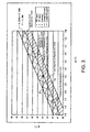
- FIG. 3 is a graph showing ranges where a temperature characteristic curve with an extreme value is easily available for the IPR quartz plate 9 with its Euler angle at (0°, 113° to 135°, +/-(40 to 49)°).
- a hatched area 4 in FIG. 3 is an area not covered by the hatched area 5, in which the range of ⁇ and ⁇ where a temperature characteristic curve with an extreme value in the above-mentioned temperature range is easily available for a resonator SAW device.
- the values of ⁇ are smaller than those in the hatched area 5 under the influence that the resonator SAW device is provided with electrodes.
- the inventor verified temperature characteristics in the border area between the hatched area 4 and the hatched area 5, and checked the validity of the hatched area 4 and the hatched area 5.
- the "IPR SAW device 3" is defined as including both transversal SAW filters and resonator SAW devices (including SAW resonators and resonator SAW filters).
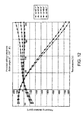
- FIGs. 9 to 12 are graphs each showing whether there is an extreme value of a cubic function for a transversal SAW filter using the IPR quartz plate 9 with its Euler angle at (0°, 113° to 135°, +/-(40 to 49)°).
- a transversal SAW filter is provided with an IDT electrode (a comb-shaped electrode) at the source side and an IDT electrode at the receiving side, with a certain interval between the electrodes, on the surface of a quartz plate which is a piezoelectric material.
- IDT electrode a comb-shaped electrode
- IDT electrode a comb-shaped electrode
- quartz plate which is a piezoelectric material
- an IDT electrode is formed on the surface of a quartz plate, which is a piezoelectric material, and a reflector electrode is provided so as to sandwich the IDT electrode. Therefore, temperature characteristics are variable depending on the width, thickness, and other factors of the IDT electrode.
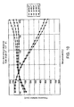
- FIG. 4 is a graph showing whether there is an extreme value of temperature characteristics as a cubic function in the temperature range from -40 to 85 °C for the resonator SAW device comprising the IPR quartz plate 9 with Euler angle at (0°, 123°, +/-(40 to 49)°).
- the thickness H and the SAW wavelength ⁇ of IDT electrodes are indicated in FIG. 25, which is a sectional view of an SAW element.
- FIG. 25 is a sectional view of an SAW element.
- FIGs. 4 and 10 show that ⁇ of the Euler angle (0°, ⁇ , ⁇ ) which represents a temperature characteristic curve of a similar pattern is different depending on whether electrodes are provided or not, even if ⁇ of the same value.
- the value of ⁇ on the border of having an extreme value is 43.7° in FIG. 10, while the value is 42.7° in FIG. 4, which is one degree smaller than in FIG. 10.
- electrodes make it difficult to find a temperature characteristic with an extreme value (a local maximum or local minimum value) in the temperature range from -40 to 85 °C within the range of ⁇ covered only by the hatched area 5 shown in FIG. 3. Then, if the area obtained by transferring the hatched area 5 shown in FIG.
- FIGs. 5 to 8 shows a temperature characteristic of the resonator SAW device whose Euler angle is (0°, 117°, ⁇ ), (0°, 129°, ⁇ ), or (0°, 135°, ⁇ ).
- These graphs show that although a temperature characteristic with an extreme value in the temperature range from -40 to 85 °C within the range of ⁇ covered only by the hatched area 5 shown in FIG. 3 is not easily available, it is easily available in the same temperature range within the area covered by both the hatched area 4 and the hatched area 5.
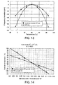
- FIG. 13 shows a temperature characteristic curve of the IPR SAW device 3 whose extreme value is set around room temperature under the condition that each value of Euler angles satisfies Formula 1, in comparison with a temperature characteristic curve of the ST-cut SAW device whose Euler angle is set at (0°, 123°, 0°). As shown in FIG. 13, including the range of Euler angles that satisfy Formula 1 makes it easier for the device 3 to have a good temperature characteristic with an extreme value compared to the case with the ST-cut SAW device.
- FIG. 15 is a diagram showing the first embodiment of the IPR SAW device 3 according to the invention.
- the IPR SAW device 3 comprises the IPR quartz plate 9 as a base plate.
- two SAW elements M1 and M2 are disposed so as to generate SAWs having the propagation directions ⁇ 1 and ⁇ 2 which differ from each other.
- Each of the two SAW elements M1 and M2 is provided with IDT electrodes 6.
- the IDT electrodes 6 are connected to an electrical terminal 7 and an electrical terminal 8 for supplying a high frequency electric field.
- the positions of the electrical terminal 7 and the electrical terminal 8 are not limited to those shown in FIG. 15.
- the electrical terminal 7 and the electrical terminal 8 can be connected to the IDT electrodes 6 at the positions shown in FIG. 27. The same can be said for second to sixth embodiments described below.
- FIG. 26 shows an example of the relation between propagation angles and turnover temperatures of SAWs in the above-mentioned range of Euler angles for the IPR SAW device 3 according to the first embodiment of the invention.
- FIG. 26 shows that the propagation angles of the two SAW elements M1 and M2 are set at (0°, 123°, 43°) and (0°, 123°, 43.4°), respectively. There is only a small angle of 0.4° made between the two SAW elements M1 and M2.
- the turnover temperature of temperature characteristics is variable with a small change in propagation directions. This means that it is possible to decrease the angle between the two SAW elements M1 and M2, both of which are disposed on the IPR quartz plate 9.
- FIG. 24 is a graph showing temperature characteristics of the IPR SAW device 3 comprising the IPR quartz plate 9, on which the two SAW elements M1 and M2 are disposed, where turnover temperatures are at 10 °C and 50 °C, respectively, in the operating temperature range from 0 to 60 °C.
- FIG. 26 shows that, if each turnover temperature tends to be low due to a manufacturing tolerance, a predetermined angle of the SAW element M1 and that of the SAW element M2 disposed on the IPR quartz plate 9 is decreased so as to raise turnover temperatures to appropriate values.
- desired turnover temperatures are readily achieved by increasing a predetermined angle of the SAW element M1 and that of the SAW element M2 disposed on the IPR quartz plate 9.
- the angle made between SAW elements can be decreased by disposing them in a manner that the propagation directions of SAWs are different with respect to each other on the IPR quartz plate 9. This makes it possible to miniaturize the IPR SAW device 3 on which the SAW elements are disposed.
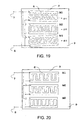
- FIG. 19 shows the second embodiment of the IPR SAW device 3 according to the invention.
- the second embodiment is different from the first embodiment in a point that three SAW elements M1, M2, and M3 are disposed on the main surface of the IPR quartz plate 9. Furthermore, the three SAW elements M1, M2, and M3 are disposed so as to generate SAWs having the propagation directions ⁇ 1, ⁇ 2, and ⁇ 3 which differ from each other.
- the turnover temperatures of the SAW elements are set to about 70 °C, 30 °C, and -10 °C, respectively, as shown in FIG. 22;
- FIG. 26 shows that the propagation angles of the three SAW elements M1, M2, and M3 are (0°, 123°, 42.8°), (0°, 123°, 43.2°) and (0°, 123°, 43.6°), respectively.
- the turnover temperature of temperature characteristics is variable with a tiny change in propagation directions. This means, it is possible to decrease the angle among a plurality of SAW elements M1 to Mn, all of which are disposed on the IPR quartz plate 9.
- FIG. 23 is a graph showing a case where a maximum value of turnover temperatures of temperature characteristics of the IPR SAW device 3 comprising the IPR quartz plate 9, on which the three SAW elements M1, M2, and M3 are disposed, is outside of an operating temperature range.
- the operating temperature range is from 0 to 60 °C, while the maximum value of turnover temperatures is 70 °C. Therefore, even if each turnover temperature is lowered by 20 °C due to manufacturing tolerances, maximum and minimum values of frequency deviations within the operating temperature range are almost free of influence.
- the second embodiment of the invention produces the following effect in addition to the above-mentioned effects (1) and (2) described in the first embodiment.
- FIG. 16 shows the third embodiment of the IPR SAW device 3 according to the invention.
- the two SAW elements M1 and M2 are disposed on the main surface of the IPR quartz plate 9.
- the third embodiment is different from the first and second embodiments in that the two SAW elements M1 and M2 are disposed so as to generate SAWs having the same propagation direction.
- FIG. 25 is a sectional view of the two SAW elements M1 and M2.
- the third embodiment shows an example where the electrode pitch P is the same for both SAW elements, while the electrode width t is different, the opposite case where the electrode pitch P is different and the electrode width t is the same is also possible. Furthermore, both the electrode pitch P and the electrode width t can be different.
- FIG. 14 shows an example of the relation between ratios ⁇ (t/P) and turnover temperatures of the IDT electrodes when Euler angles satisfy Formula 1, and an example of the relation between ratios ⁇ and turnover temperatures of the IDT electrodes of the ST-cut SAW device whose Euler angle is set at (0°, 123°, 0°).
- the turnover temperatures of the IPR SAW device 3 are more variable than those of the ST-cut SAW device, because of the value ⁇ . This makes it possible for the IPR SAW device 3 to have a wider range of turnover temperatures. Therefore, a good temperature characteristic is easily available in a wider range of temperatures.
- FIG. 16 shows that the ratios ⁇ 1 and ⁇ 2 of the IDT electrodes of the two SAW elements M1 and M2 are set to about 0.4 and 0.55, respectively.
- FIG. 24 is a graph showing temperature characteristics of the IPR SAW device 3 comprising the IPR quartz plate 9, on which the two SAW elements M1 and M2 are disposed, where turnover temperatures are 10 °C and 50 °C in the operating temperature range from 0 to 60 °C.
- FIG. 26 shows an example of the relation between values ⁇ and turnover temperatures in the range of Euler angles which satisfy Formula 1 for the IPR SAW device 3 according to the embodiment.
- FIG. 26 shows that, if each turnover temperature shown in FIG. 24 tends to be low due to a manufacturing tolerance, a predetermined angle of the SAW element M1 and that of the SAW element M2 disposed on the IPR quartz plate 9 are decreased so as to raise turnover temperatures to appropriate values. Conversely, for example, when the operating temperature range is changed to a higher one than in FIG. 24, desired turnover temperatures are readily achieved by increasing a predetermined angle of the SAW element M1 and that of the SAW element M2 disposed on the IPR quartz plate 9.
- the third embodiment of the invention produces the following effect in addition to the above-mentioned effects (1), (2), and (3) described in the first embodiment.
- the IDT electrodes of the SAW element to be disposed can be further miniaturized by being disposed in parallel.
- FIG. 20 shows the fourth embodiment of the IPR SAW device 3 according to the invention.
- Three SAW elements M1, M2, and M3 are disposed on the main surface of the IPR quartz plate 9.
- the three SAW elements M1, M2, and M3 are disposed so as to generate SAWs having the same propagation direction.
- FIG. 14 shows that the ratios ⁇ 1, ⁇ 2, and ⁇ 3 of the IDT electrodes of the three SAW elements M1, M2, and M3 are set to 0.325, 0.475, and 0.625, respectively.
- disposing all of the three SAW elements M1, M2, and M3, whose ratios ⁇ are different from each other, on the IPR quartz plate 9 makes it possible not only to provide a good temperature characteristic, which is not attained by a single SAW element, but also to dispose the IDT electrodes of the three SAW elements in parallel without tilting them.
- FIG. 23 is a graph showing a case where the maximum turnover temperature of the temperature characteristics of the IPR SAW device 3 comprising the IPR quartz plate 9, on which the three SAW elements M1, M2, and M3 are disposed, is outside of the operating temperature range.
- the operating temperature range is from -20 to 60 °C, while the maximum turnover temperature is 70 °C. Therefore, even if each turnover temperature is lowered by 20 °C due to a manufacturing tolerance, maximum and minimum values of frequency deviations within the operating temperature range are almost free of influence. In other words, even if turnover temperatures Tp1 to Tpn of temperature characteristics of a plurality of SAW elements M1 to Mn deviate from desired values due to a manufacturing tolerance, a good temperature characteristic in a certain operating temperature range is available.
- the fourth embodiment of the invention also produces the above-mentioned effects (1), (2), (4), and (5) described in the first to third embodiments.
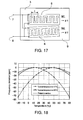
- FIG. 17 shows the fifth embodiment of the IPR SAW device 3 according to the invention.
- Two SAW elements M1 and M2 are disposed on the main surface of the IPR quartz plate 9 so as to generate SAWs having the propagation directions ⁇ 1 and ⁇ 2 which are different from each other.
- the fifth embodiment is different from the first to fourth embodiments in that the ratios ⁇ 1 and ⁇ 2 of the two SAW elements M1 and M2 are different from each other.
- the turnover temperature of temperature characteristics is variable with a small change in the propagation directions.
- ⁇ decreases along with a high frequency
- an extremely large value ⁇ is likely to cause a short-circuit due to a foreign substance, on one hand.
- an extremely small value ⁇ is likely to cause an electrode breaking.
- the fifth embodiment makes these defects less likely to occur.
- the fifth embodiment of the invention produces the following effect in addition to the above-mentioned effects (1), (2), and (3) described in the first embodiment.
- the fifth embodiment makes it possible to decrease the possibility of defects such as a short-circuit and a breaking of the IDT electrodes 6.
- FIG. 21 shows the sixth embodiment of the IPR SAW device 3 according to the invention.
- Three SAW elements M1, M2, and M3 are disposed on the main surface of the IPR quartz plate 9.
- the three SAW elements M1, M2, and M3 are disposed so as to generate SAWs having the propagation directions ⁇ 1, ⁇ 2, and ⁇ 3 which are different from each other.
- both the propagation directions ⁇ and the ratios ⁇ of the IDT electrodes 6 of the three SAW elements different as mentioned above, it is possible not only to further decrease an angle among the three SAW elements M1, M2, and M3, but also to change turnover temperatures without extremely increasing or decreasing the ratios ⁇ of the IDT electrodes 6. That is to say, it is possible not only to decrease an angle among a plurality of SAW elements M1 to Mn, but also to change turnover temperatures without extremely increasing or decreasing the ratios ⁇ 1 to ⁇ n of a plurality of the IDT electrodes 6.
- the sixth embodiment of the invention also produces the above-mentioned effects (1), (2), (4), and (6) described in the first, second, and fifth embodiments.
Abstract
Description
- The present invention relates to a surface acoustic wave (SAW) device, and more particularly to an SAW device that comprises a quartz plate and has a frequency that changes only little with temperature variations; the invention also relates to a method of adjusting the temperature characteristic of such a SAW device.
- SAW devices which comprise interdigital transducer (IDT) electrodes on the main surface of a piezoelectric plate represented by a piece of quartz so as to oscillate in a high-frequency region in a stable manner are widely known. Among such SAW devices, ST-cut SAW devices which comprise an ST-cut quartz plate as a piezoelectric plate, transmit SAWs in the direction of the X-axis (the electrical axis) of the ST-cut quartz plate, and generate a Rayleigh wave, which is a kind of SAW, are widely known to have a relatively small temperature dependency of their frequency.
- In order to further reduce frequency changes due to temperature variations, a plurality of SAW elements are disposed on an ST-cut quartz plate in a manner that the propagation directions of SAWs generated by the SAW elements differ from each other in one case, or in a manner that the electrode thicknesses of the IDT electrodes differ from each other in another case (see JP-A-53-145595, for example).
- Alternatively, an ST-cut quartz plate is further rotated around the Z'-axis in-plane (i.e., in the X-Y' plane, hereinafter called "in-plane rotated ST-cut quartz plate" and abbreviated to "IPR quartz plate"). An SAW element disposed on such IPR quartz plate is hereinafter called an "in-plane rotated ST-cut SAW device" (see JP-B-63-18892, for example), abbreviated to "IPR SAW device".
- However, the turnover temperature of the frequency versus temperature characteristic, i.e., the temperature at which the frequency assumes an extreme value (maximum or minimum), of an ST-cut SAW device changes little with propagation direction. For example, even if the propagation direction is changed by 10°, the turnover temperature changes by 20 °C or less (see Minowa Jumonji: "Suishouban wo Mochiita Danseihyomenha Soshi no Chushin Shuhasu to sono Ondo Tokusei (Central Frequencies and Temperature Characteristics of Surface Acoustic Wave Elements Using a Quartz Plate)." Technical Report of IEICE 1976 (July), No. 78: 9-16, US76-23, Institute of Electronics, Information, and Communication Engineers, Japan, for example). Thus, when disposing a plurality of SAW elements on an ST-cut quartz plate, it is necessary to increase the angle among the SAW elements. In particular, when increasing the number of SAW elements to be disposed in order to decrease frequency changes in a wide temperature range, the angle made between an SAW element which provides the minimum turnover temperature and an SAW element which provides the maximum turnover temperature is inevitably large. Consequently, it is difficult to miniaturize an SAW device on which a plurality of SAW elements are disposed on an ST-cut quartz plate in a manner that the propagation directions of SAWs generated by each of the SAW elements are different. Furthermore, IDT electrodes disposed in a tilted position involve the following problem as frequency increases.
- The pattern of IDT electrodes is generally formed by using a photomask process. In the photomask process, a diagonal line is formed by a group of short lines aligned in a manner of stairs. Since lines in IDT electrodes become thin for high frequencies, such a stairlike arrangement of the group of short lines cannot be neglected, since the arrangement of IDT electrodes disposed in a tilted position comes to be seen as non-smooth (that is, the electrode width of the IDT electrodes becomes unstable). The non-smooth arrangement of IDT electrodes could cause unnecessary oscillations, which may bring a defect.
- In the meantime, when disposing a plurality of SAW elements having different electrode thicknesses of IDT electrodes on an ST-cut quartz plate, it is possible to dispose the IDT electrodes in parallel. However, it is necessary to form a plurality of settings of electrode thicknesses on the same quartz plate, and thereby the manufacturing process becomes complicated.
- The IPR SAW device is far superior in temperature characteristics to the ST-cut SAW device. As regards the temperature characteristic of an SAW element, however, it has a problem that it does not provide sufficient accuracy, since the wider the operating temperature range is, the larger frequency changes become.
- In consideration of the above-mentioned problems, the present invention aims to provide an SAW device which provides a good temperature characteristic in a wide temperature range and which can be miniaturized. The invention also aims to provide a method of adjusting the temperature characteristic of the SAW device.
- This object is achieved by a surface acoustic wave device as claimed in
claims - The embodiment according to
claim 1 makes it possible to change turnover temperatures without making the propagation directions ψ1 to ψn much different from each other. - The embodiment according to
claim 2 makes it possible to provide a good temperature characteristic in a wide range of temperatures, and to dispose the IDT electrodes in parallel. - The embodiment according to
claim 3 makes it possible to change turnover temperatures without making the propagation directions ψ1 to ψn much different from each other, and to provide a good temperature characteristic in a wide range of temperatures. - The embodiment according to
claim 4 makes it possible to provide a good temperature characteristic in the operating temperature range, even if the turnover temperatures Tp1 to Tpn of the temperature characteristics of the SAW elements M1 to Mn deviate from desired values due to manufacturing tolerances. - According to the invention, the temperature characteristic of an SAW device is adjusted by adjusting an angle of disposing the SAW device on the quartz plate cut out so as to have the Euler angle at (0°, 113° to 135°, +/-(40 to 49)°). This makes it possible to provide a good temperature characteristic in an operating temperature range, even if turnover temperatures Tp1 to Tpn of temperature characteristics of the SAW elements M1 to Mn deviate from desired values because of manufacturing tolerances, and to readily change a temperature range which provides a good temperature characteristic when changing the operating temperature range.
- The best mode for carrying out the present invention is described below with reference to the accompanying drawings. The embodiments shown below do not limit the invention as defined in the claims. Furthermore, all the components shown in the embodiments below are not always necessary to work as a solution provided by the invention as defined by the claims.
- FIG. 1
- is a drawing illustrating cut angles of quartz.
- FIG. 2
- is a graph showing a temperature characteristic curve with an extreme value.
- FIG. 3
- is a graph showing ranges where a temperature characteristic curve with an extreme value is easily available for the IPR quartz plate whose Euler angle is set at (0°, 113° to 135°, +/-(40 to 49)°).
- FIG.4
- is a graph showing whether there is an extreme value of the cubic function for the resonator SAW device comprising the IPR quartz plate whose Euler angle is set at (0°, 113° to 135°, +/-(40 to 49)°).
- FIG. 5
- is a graph showing whether there is an extreme value of the cubic function for the resonator SAW device comprising the IPR quartz plate whose Euler angle is set at (0°, 113° to 135°, +/-(40 to 49)°).
- FIG. 6
- is a graph showing whether there is an extreme value of the cubic function for the resonator SAW device comprising the IPR quartz plate whose Euler angle is set at (0°, 113° to 135°, +/-(40 to 49)°).
- FIG. 7
- is a graph showing whether there is an extreme value of the cubic function for the resonator SAW device comprising the IPR quartz plate whose Euler angle is set at (0°, 113° to 135°, +/-(40 to 49)°).
- FIG. 8
- is a graph showing whether there is an extreme value of the cubic function for the resonator SAW device comprising the IPR quartz plate whose Euler angle is set at (0°, 113° to 135°, +/-(40 to 49)°).
- FIG. 9
- is a graph showing whether there is an extreme value of the cubic function for the transversal SAW filter comprising the IPR quartz plate whose Euler angle is set at (0°, 113° to 135°, +/-(40 to 49)°).
- FIG. 10
- is a graph showing whether there is an extreme value of the cubic function for the transversal SAW filter comprising the IPR quartz plate whose Euler angle is set at (0°, 113° to 135°, +/-(40 to 49)°).
- FIG. 11
- is a graph showing whether there is an extreme value of the cubic function for the transversal SAW filter comprising the IPR quartz plate whose Euler angle is set at (0°, 113° to 135°, +/-(40 to 49)°).
- FIG. 12
- is a graph showing whether there is an extreme value of the cubic function for the transversal SAW filter comprising the IPR quartz plate whose Euler angle is set at (0°, 113° to 135°, +/-(40 to 49)°).
- FIG. 13
- is a graph comparing a temperature characteristic curve of the ST-cut SAW device whose Euler angle is set at (0°, 123°, 0°) with a temperature characteristic curve of the IPR SAW device.
- FIG. 14
- is a diagram showing the relation between ratios "η" and turnover temperatures, under the condition that Euler angle is set at (0°, 123°, 0°), or (0°, 123°, 43.2°) according to an embodiment of the invention, when H/λ is 0.03.
- FIG. 15
- is a diagram showing the first embodiment of the IPR SAW device according to the invention.
- FIG. 16
- is a diagram showing the third embodiment of the IPR SAW device according to the invention.
- FIG. 17
- is a diagram showing the fifth embodiment of the IPR SAW device according to the invention.
- FIG. 18
- is a diagram showing temperature characteristics of an embodiment of the IPR SAW device according to the invention.
- FIG. 19
- is a diagram showing the second embodiment of the IPR SAW device according to the invention.
- FIG. 20
- is a diagram showing the fourth embodiment of the IPR SAW device according to the invention.
- FIG. 21
- is a diagram showing the sixth embodiment of the IPR SAW device according to the invention.
- FIG.22
- is a diagram showing temperature characteristics of an embodiment of the IPR SAW device according to the invention.
- FIG. 23
- is a diagram showing temperature characteristics of an embodiment of the IPR SAW device according to the invention.
- FIG. 24
- is a diagram showing temperature characteristics of an embodiment of the IPR SAW device according to the invention.
- FIG. 25
- is a sectional view of an SAW element, indicating the electrode width, the electrode pitch, "H" and "λ."
- FIG. 26
- is a diagram showing the relation between values ψ and turnover temperatures, under the condition that Euler angle is set at (0°, 123°, ψ) according to an embodiment of the invention, when H/λ is 0.03 or 0.04, and η is 0.5.
- FIG. 27
- is a diagram showing the first embodiment of the IPR SAW device according to the invention.
- A first embodiment of the present invention is described below with reference to the drawings.
- FIG. 1 is a drawing illustrating cut angles of quartz. When forming a piezoelectric resonator by cutting quartz, it is widely known that the temperature characteristic depends on the direction of cutting. As shown in FIG. 1, the crystal axes of quartz are defined by the electrical axis (X), the mechanical axis (Y), and the optical axis (Z). A
quartz Z plate 2 with Euler angle (ø, , ψ) of (0°, 0°, 0°) is rotated around the electrical axis (X), by an angle of 113° to 135° to become an ST-cutquartz plate 1 having new axes of coordinate (X, Y', Z'). Theplate 1, called an ST-cut plate is cut out along the new axes of coordinate (X, Y', Z'). Next, the ST-cutquartz plate 1 is further rotated around the Z' axis of the ST-cutquartz plate 1, by an angle ψ of +/- (40° to 49°), so as to set the direction of transmitting SAWs to this angle. A piezoelectric resonator including this further rotated plate is called herein an IPR SAW device 3 (in-plane rotated ST-cut SAW device). TheIPR SAW device 3 is known to have excellent temperature characteristics, which have been regarded as a quadratic function like that of other ST-cut devices. However, after thorough consideration, the inventor found that the temperature characteristic represents a cubic function with an inflection point at around 110 °C. Since the temperature characteristics are generally not observed at temperatures well over 110 °C, the fact that the temperature characteristics of theIPR SAW device 3 using anIPR quartz plate 9 is represented by a cubic function has been unknown. - FIG. 2 is a graph showing a temperature characteristic curve with an extreme value. As mentioned before, the temperature characteristic of the
IPR SAW device 3 has an inflection point at around 110 °C. If the operating temperature range of the device is set below the inflection point, for example, at - 40 to 85 °C, this device is used within a temperature range (the area surrounded by a square in FIG. 2) including a maximum (Tp) below the inflection point of the temperature characteristic curve as a cubic function. - FIG. 3 is a graph showing ranges where a temperature characteristic curve with an extreme value is easily available for the
IPR quartz plate 9 with its Euler angle at (0°, 113° to 135°, +/-(40 to 49)°). - After thorough studies, in the range of the graph having temperature characteristics as a cubic function, the inventor found the range of and ψ where a temperature characteristic curve with an extreme value (a local maximum or local minimum) in the temperature range from -40 to 85 °C is easily available for a transversal SAW device. This range is shown in the graph as a hatched
area 5. - On the other hand, a hatched
area 4 in FIG. 3 is an area not covered by the hatchedarea 5, in which the range of and ψ where a temperature characteristic curve with an extreme value in the above-mentioned temperature range is easily available for a resonator SAW device. In the hatchedarea 4, the values of ψ are smaller than those in the hatchedarea 5 under the influence that the resonator SAW device is provided with electrodes. The area that covers both the hatchedarea 4 and the hatchedarea 5 is defined by the formula below. - By performing in-plane rotation around the Z' axis in the area that covers both the hatched
area 4 and the hatchedarea 5, a frequency versus temperature characteristic curve with an extreme value is easily available. - The inventor verified temperature characteristics in the border area between the hatched
area 4 and the hatchedarea 5, and checked the validity of the hatchedarea 4 and the hatchedarea 5. - Also according to the first embodiment of the invention, the "
IPR SAW device 3" is defined as including both transversal SAW filters and resonator SAW devices (including SAW resonators and resonator SAW filters). - FIGs. 9 to 12 are graphs each showing whether there is an extreme value of a cubic function for a transversal SAW filter using the
IPR quartz plate 9 with its Euler angle at (0°, 113° to 135°, +/-(40 to 49)°). - According to these graphs, the inventor found the range of and ψ in which a temperature characteristic with an extreme value in the temperature range from -40 to 85 °C is easily available for an SAW device having a transversal SAW filter. This range is shown in FIG. 3 as a hatched
area 5, which is defined by the formula below. - Moreover, the inventor found various patterns for not only temperature characteristics of the transversal SAW filter, but also those of resonator SAW devices as a result of thorough studies. Specifically, a transversal SAW filter is provided with an IDT electrode (a comb-shaped electrode) at the source side and an IDT electrode at the receiving side, with a certain interval between the electrodes, on the surface of a quartz plate which is a piezoelectric material. As regards such an SAW filter, because nothing is formed between the IDT electrodes, the width, thickness, and other factors of the electrodes cause little change in temperature characteristics of frequencies (that is, changing the shape of the electrodes does not have much effect on the temperature characteristics). Regarding a resonator SAW device, however, an IDT electrode is formed on the surface of a quartz plate, which is a piezoelectric material, and a reflector electrode is provided so as to sandwich the IDT electrode. Therefore, temperature characteristics are variable depending on the width, thickness, and other factors of the IDT electrode.
- FIG. 4 is a graph showing whether there is an extreme value of temperature characteristics as a cubic function in the temperature range from -40 to 85 °C for the resonator SAW device comprising the
IPR quartz plate 9 with Euler angle at (0°, 123°, +/-(40 to 49)°). Here, the ratio of the electrode thickness H to the SAW wavelength λ is H/λ = 0.03. The thickness H and the SAW wavelength λ of IDT electrodes are indicated in FIG. 25, which is a sectional view of an SAW element. As shown in FIG. 4, when the in-plane rotation angle ψ is set smaller than angles covered by the hatchedarea 4 shown in FIG. 3, it is clear that temperature characteristics do not have an extreme value in the temperature range from -40 to 85 °C. In contrast, when the in-plane rotation angle ψ is set larger than angles covered by the hatchedarea 4 shown in FIG. 3, it is clear that temperature characteristics have an extreme value. For example, FIG. 4 shows that when ψ is 44°, there is an extreme value around -30 °C, which is covered by the hatchedarea 5. - FIGs. 4 and 10 show that ψ of the Euler angle (0°, , ψ) which represents a temperature characteristic curve of a similar pattern is different depending on whether electrodes are provided or not, even if of the same value. For example, the value of ψ on the border of having an extreme value is 43.7° in FIG. 10, while the value is 42.7° in FIG. 4, which is one degree smaller than in FIG. 10. In other words, electrodes make it difficult to find a temperature characteristic with an extreme value (a local maximum or local minimum value) in the temperature range from -40 to 85 °C within the range of ψ covered only by the hatched
area 5 shown in FIG. 3. Then, if the area obtained by transferring the hatchedarea 5 shown in FIG. 3 so as to make the value ψ one degree smaller (namely, the hatched area 4), and the hatchedarea 5 are both included, it is possible to easily find a temperature characteristic with an extreme value in the temperature range from -40 to 85 °C regardless of whether electrodes are provided. The area that covers both the hatchedarea 4 and the hatchedarea 5 is defined byFormula 1. - Each of FIGs. 5 to 8 shows a temperature characteristic of the resonator SAW device whose Euler angle is (0°, 117°, ψ), (0°, 129°, ψ), or (0°, 135°, ψ). These graphs show that although a temperature characteristic with an extreme value in the temperature range from -40 to 85 °C within the range of ψ covered only by the hatched
area 5 shown in FIG. 3 is not easily available, it is easily available in the same temperature range within the area covered by both the hatchedarea 4 and the hatchedarea 5. - FIG. 13 shows a temperature characteristic curve of the
IPR SAW device 3 whose extreme value is set around room temperature under the condition that each value of Euler angles satisfiesFormula 1, in comparison with a temperature characteristic curve of the ST-cut SAW device whose Euler angle is set at (0°, 123°, 0°). As shown in FIG. 13, including the range of Euler angles that satisfyFormula 1 makes it easier for thedevice 3 to have a good temperature characteristic with an extreme value compared to the case with the ST-cut SAW device. - FIG. 15 is a diagram showing the first embodiment of the
IPR SAW device 3 according to the invention. TheIPR SAW device 3 comprises theIPR quartz plate 9 as a base plate. On the main surface of theIPR quartz plate 9, two SAW elements M1 and M2 are disposed so as to generate SAWs having the propagation directions ψ1 and ψ2 which differ from each other. Each of the two SAW elements M1 and M2 is provided withIDT electrodes 6. Furthermore, theIDT electrodes 6 are connected to anelectrical terminal 7 and anelectrical terminal 8 for supplying a high frequency electric field. The positions of theelectrical terminal 7 and theelectrical terminal 8 are not limited to those shown in FIG. 15. For example, theelectrical terminal 7 and theelectrical terminal 8 can be connected to theIDT electrodes 6 at the positions shown in FIG. 27. The same can be said for second to sixth embodiments described below. - FIG. 26 shows an example of the relation between propagation angles and turnover temperatures of SAWs in the above-mentioned range of Euler angles for the
IPR SAW device 3 according to the first embodiment of the invention. - For example, when the two SAW elements, which satisfy H/λ = 0.03, in FIG. 15 are electrically connected in parallel so as to provide a good temperature characteristic in a wide range of temperatures by setting the turnover temperature of the SAW elements to about 50 °C and 10 °C, respectively, as shown in FIG. 18, FIG. 26 shows that the propagation angles of the two SAW elements M1 and M2 are set at (0°, 123°, 43°) and (0°, 123°, 43.4°), respectively. There is only a small angle of 0.4° made between the two SAW elements M1 and M2.
- That is to say, in the range of Euler angles which satisfy
Formula 1, the turnover temperature of temperature characteristics is variable with a small change in propagation directions. This means that it is possible to decrease the angle between the two SAW elements M1 and M2, both of which are disposed on theIPR quartz plate 9. - FIG. 24 is a graph showing temperature characteristics of the
IPR SAW device 3 comprising theIPR quartz plate 9, on which the two SAW elements M1 and M2 are disposed, where turnover temperatures are at 10 °C and 50 °C, respectively, in the operating temperature range from 0 to 60 °C. For example, FIG. 26 shows that, if each turnover temperature tends to be low due to a manufacturing tolerance, a predetermined angle of the SAW element M1 and that of the SAW element M2 disposed on theIPR quartz plate 9 is decreased so as to raise turnover temperatures to appropriate values. Conversely, for example, when the operating temperature range is changed to a higher one than in FIG. 24, desired turnover temperatures are readily achieved by increasing a predetermined angle of the SAW element M1 and that of the SAW element M2 disposed on theIPR quartz plate 9. - In other words, even if turnover temperatures Tp1 and Tp2 of the temperature characteristics of the two SAW elements M1 and M2, respectively, deviate from desired values, a good temperature characteristic in a certain operating temperature range is available. Furthermore, when changing the operating temperature range, it is also possible to change without difficulty the range of temperatures where good temperature characteristics are available.
- In summary, the effects of the first embodiment are as follows.
- (1) The angle made between SAW elements can be decreased by disposing them in a manner that the propagation directions of SAWs are different with respect to each other on the
IPR quartz plate 9. This makes it possible to miniaturize theIPR SAW device 3 on which the SAW elements are disposed. - (2) It is possible to readily respond to a deviation of temperature characteristics caused by manufacturing tolerances, and changes in operating temperature ranges.
- (3) A good temperature characteristic is available in a wide temperature range.
- Next, a second embodiment of the present invention is described below with reference to the drawings.
- FIG. 19 shows the second embodiment of the
IPR SAW device 3 according to the invention. The second embodiment is different from the first embodiment in a point that three SAW elements M1, M2, and M3 are disposed on the main surface of theIPR quartz plate 9. Furthermore, the three SAW elements M1, M2, and M3 are disposed so as to generate SAWs having the propagation directions ψ1, ψ2, and ψ3 which differ from each other. - In FIG. 19, the three SAW elements M1, M2, and M3, all of which satisfy H/λ = 0.03, are electrically connected in parallel. In order to provide a good temperature characteristic in a wider range of temperatures the turnover temperatures of the SAW elements are set to about 70 °C, 30 °C, and -10 °C, respectively, as shown in FIG. 22; FIG. 26 shows that the propagation angles of the three SAW elements M1, M2, and M3 are (0°, 123°, 42.8°), (0°, 123°, 43.2°) and (0°, 123°, 43.6°), respectively.
- To put it another way, there is only a small angle of 0.8° between an SAW element providing a minimum turnover temperature and an SAW element providing a maximum value of turnover temperatures.
- That is to say, in the range of Euler angles which satisfy
Formula 1, the turnover temperature of temperature characteristics is variable with a tiny change in propagation directions. This means, it is possible to decrease the angle among a plurality of SAW elements M1 to Mn, all of which are disposed on theIPR quartz plate 9. - FIG. 23 is a graph showing a case where a maximum value of turnover temperatures of temperature characteristics of the
IPR SAW device 3 comprising theIPR quartz plate 9, on which the three SAW elements M1, M2, and M3 are disposed, is outside of an operating temperature range. In this case, the operating temperature range is from 0 to 60 °C, while the maximum value of turnover temperatures is 70 °C. Therefore, even if each turnover temperature is lowered by 20 °C due to manufacturing tolerances, maximum and minimum values of frequency deviations within the operating temperature range are almost free of influence. As a result, even if turnover temperatures Tp1, Tp2, and Tp3 of temperature characteristics of the three SAW elements M1, M2, and M3, respectively, deviate from desired values due to a manufacturing tolerance, a good temperature characteristic in a certain operating temperature range is available. - In other words, even if turnover temperatures Tp1 to Tpn of temperature characteristics of the SAW elements M1 to Mn, respectively, deviate from desired values due to a manufacturing tolerance, a good temperature characteristic in a certain operating temperature range is available. Moreover, when changing the operating temperature range, it is also possible to change without difficulty the range of temperatures where a good temperature characteristic is available.
- As described in detail above, the second embodiment of the invention produces the following effect in addition to the above-mentioned effects (1) and (2) described in the first embodiment.
- (4) It is possible not only to provide a good temperature characteristic in a wider range of operating temperatures, but also to readily respond to larger changes in operating temperature ranges.
- Next, a third embodiment of the present invention is described below with reference to the drawings.
- FIG. 16 shows the third embodiment of the
IPR SAW device 3 according to the invention. The two SAW elements M1 and M2 are disposed on the main surface of theIPR quartz plate 9. The third embodiment is different from the first and second embodiments in that the two SAW elements M1 and M2 are disposed so as to generate SAWs having the same propagation direction. FIG. 25 is a sectional view of the two SAW elements M1 and M2. On the main surface of theIPR quartz plate 9, theIDT electrodes 6, whose electrode width t and electrode pitch P are indicated in the sectional view, is disposed. The third embodiment is also different from the first and second embodiments in that the ratios η1 and η2 (η = t/P) obtained by dividing the electrode width t by the electrode pitch P of the IDT electrodes of the two SAW elements M1 and M2 are different. - Although the third embodiment shows an example where the electrode pitch P is the same for both SAW elements, while the electrode width t is different, the opposite case where the electrode pitch P is different and the electrode width t is the same is also possible. Furthermore, both the electrode pitch P and the electrode width t can be different.
- Regarding the
IPR SAW device 3 of the third embodiment, FIG. 14 shows an example of the relation between ratios η (t/P) and turnover temperatures of the IDT electrodes when Euler angles satisfyFormula 1, and an example of the relation between ratios η and turnover temperatures of the IDT electrodes of the ST-cut SAW device whose Euler angle is set at (0°, 123°, 0°). As shown in FIG. 14, the turnover temperatures of theIPR SAW device 3 are more variable than those of the ST-cut SAW device, because of the value η. This makes it possible for theIPR SAW device 3 to have a wider range of turnover temperatures. Therefore, a good temperature characteristic is easily available in a wider range of temperatures. - For example, when the two SAW elements, which satisfy H/λ = 0.03, in FIG. 16 are electrically connected in parallel so as to provide a good temperature characteristic in a wide range of temperatures by setting the turnover temperature of the SAW elements to about 50 °C and 10 °C, respectively, as shown in FIG. 18, FIG. 14 shows that the ratios η1 and η2 of the IDT electrodes of the two SAW elements M1 and M2 are set to about 0.4 and 0.55, respectively.
- Therefore, in a range of Euler angles which satisfy
Formula 1, by disposing both SAW elements M1 and M2 whose ratios differ on theIPR quartz plate 9, a good temperature characteristic can be obtained, which is not attained by a single SAW element. Moreover, it is possible to dispose the IDT electrodes of the SAW elements not in a tilted position but in parallel. This makes it possible to miniaturize theIPR SAW device 3 comprising theIPR quartz plate 9 on which the SAW elements M1 and M2 are disposed. - FIG. 24 is a graph showing temperature characteristics of the
IPR SAW device 3 comprising theIPR quartz plate 9, on which the two SAW elements M1 and M2 are disposed, where turnover temperatures are 10 °C and 50 °C in the operating temperature range from 0 to 60 °C. FIG. 26 shows an example of the relation between values ψ and turnover temperatures in the range of Euler angles which satisfyFormula 1 for theIPR SAW device 3 according to the embodiment. - For example, FIG. 26 shows that, if each turnover temperature shown in FIG. 24 tends to be low due to a manufacturing tolerance, a predetermined angle of the SAW element M1 and that of the SAW element M2 disposed on the
IPR quartz plate 9 are decreased so as to raise turnover temperatures to appropriate values. Conversely, for example, when the operating temperature range is changed to a higher one than in FIG. 24, desired turnover temperatures are readily achieved by increasing a predetermined angle of the SAW element M1 and that of the SAW element M2 disposed on theIPR quartz plate 9. - In other words, even if turnover temperatures Tp1 and Tp2 of temperature characteristics of the two SAW elements M1 and M2, respectively, deviate from desired values, a good temperature characteristic in a certain operating temperature range is available. Furthermore, when changing the operating temperature range, it is also possible to change without difficulty the range of temperatures where a good temperature characteristic is available.
- As described in detail above, the third embodiment of the invention produces the following effect in addition to the above-mentioned effects (1), (2), and (3) described in the first embodiment.
- (5) The IDT electrodes of the SAW element to be disposed can be further miniaturized by being disposed in parallel.
- Next, a fourth embodiment of the present invention is described below with reference to the drawings.
- FIG. 20 shows the fourth embodiment of the
IPR SAW device 3 according to the invention. Three SAW elements M1, M2, and M3 are disposed on the main surface of theIPR quartz plate 9. The three SAW elements M1, M2, and M3 are disposed so as to generate SAWs having the same propagation direction. Furthermore, the fourth embodiment is different from the first to third embodiments in that the ratios η1, η2, and η3 (η = t/P) of the three SAW elements M1, M2, and M3 are different from each other. - When the three SAW elements M1, M2, and M3, which satisfy H/λ = 0.03, in FIG. 20 are electrically connected in parallel so as to provide a good temperature characteristic in a wider range of temperatures by setting the turnover temperature of the SAW elements to about 70 °C, 30 °C and - 10 °C, respectively, as shown in FIG. 22, FIG. 14 shows that the ratios η1, η2, and η3 of the IDT electrodes of the three SAW elements M1, M2, and M3 are set to 0.325, 0.475, and 0.625, respectively.
- Therefore, in a range of Euler angles which satisfy
Formula 1, disposing all of the three SAW elements M1, M2, and M3, whose ratios η are different from each other, on theIPR quartz plate 9 makes it possible not only to provide a good temperature characteristic, which is not attained by a single SAW element, but also to dispose the IDT electrodes of the three SAW elements in parallel without tilting them. - In other words, better temperature characteristics can be achieved by disposing a plurality of SAW elements M1 to Mn whose ratios η are different from each other on the
IPR quartz plate 9. Moreover, it is possible to dispose the IDT electrodes of a plurality of SAW elements M1 to Mn not in a tilted position but in parallel. - FIG. 23 is a graph showing a case where the maximum turnover temperature of the temperature characteristics of the
IPR SAW device 3 comprising theIPR quartz plate 9, on which the three SAW elements M1, M2, and M3 are disposed, is outside of the operating temperature range. In this case, the operating temperature range is from -20 to 60 °C, while the maximum turnover temperature is 70 °C. Therefore, even if each turnover temperature is lowered by 20 °C due to a manufacturing tolerance, maximum and minimum values of frequency deviations within the operating temperature range are almost free of influence. In other words, even if turnover temperatures Tp1 to Tpn of temperature characteristics of a plurality of SAW elements M1 to Mn deviate from desired values due to a manufacturing tolerance, a good temperature characteristic in a certain operating temperature range is available. - As described in detail above, the fourth embodiment of the invention also produces the above-mentioned effects (1), (2), (4), and (5) described in the first to third embodiments.
- Next, a fifth embodiment of the present invention is described below with reference to the drawings.
- FIG. 17 shows the fifth embodiment of the
IPR SAW device 3 according to the invention. Two SAW elements M1 and M2 are disposed on the main surface of theIPR quartz plate 9 so as to generate SAWs having the propagation directions ψ1 and ψ2 which are different from each other. Furthermore, the fifth embodiment is different from the first to fourth embodiments in that the ratios η1 and η2 of the two SAW elements M1 and M2 are different from each other. - As shown in FIG. 26, in the range of Euler angles which satisfy
Formula 1, the turnover temperature of temperature characteristics is variable with a small change in the propagation directions. In other words, it is possible to decrease the angle between the two SAW elements M1 and M2, both of which are disposed on theIPR quartz plate 9. - In addition, as shown in FIG. 14, in a range of Euler angles which satisfy
Formula 1, disposing both of the two SAW elements M1 and M2, whose ratios η are different from each other, on theIPR quartz plate 9 makes it possible to provide a good temperature characteristic, which is not attained by a single SAW element. It is also possible to dispose the IDT electrodes of the two SAW elements in parallel. - In the fifth embodiment, by making the propagation directions ψ and the ratios η (η = t/P) of the
IDT electrodes 6 between the two SAW elements different as mentioned above, it is possible not only to further decrease the angle between the two SAW elements M1 and M2, but also to change turnover temperatures without extremely increasing or decreasing the ratios η of theIDT electrodes 6. In particular, when λ decreases along with a high frequency, an extremely large value η is likely to cause a short-circuit due to a foreign substance, on one hand. On the other, an extremely small value η is likely to cause an electrode breaking. The fifth embodiment makes these defects less likely to occur. - As described in detail above, the fifth embodiment of the invention produces the following effect in addition to the above-mentioned effects (1), (2), and (3) described in the first embodiment.
- (6) While it is necessary to decrease the electrode width and the electrode pitch as frequency increases, the fifth embodiment makes it possible to decrease the possibility of defects such as a short-circuit and a breaking of the
IDT electrodes 6. - Next, a sixth embodiment of the present invention is described below with reference to the drawings.
- FIG. 21 shows the sixth embodiment of the
IPR SAW device 3 according to the invention. Three SAW elements M1, M2, and M3 are disposed on the main surface of theIPR quartz plate 9. The three SAW elements M1, M2, and M3 are disposed so as to generate SAWs having the propagation directions ψ1, ψ2, and ψ3 which are different from each other. Furthermore, the sixth embodiment is different from the first to fifth embodiments in that the ratios η1, η2, and η3 (η = t/P) of the IDT electrodes of the three SAW elements M1, M2, and M3 are different from each other. - In the sixth embodiment, by making both the propagation directions ψ and the ratios η of the
IDT electrodes 6 of the three SAW elements different as mentioned above, it is possible not only to further decrease an angle among the three SAW elements M1, M2, and M3, but also to change turnover temperatures without extremely increasing or decreasing the ratios η of theIDT electrodes 6. That is to say, it is possible not only to decrease an angle among a plurality of SAW elements M1 to Mn, but also to change turnover temperatures without extremely increasing or decreasing the ratios η1 to ηn of a plurality of theIDT electrodes 6. - As described in detail above, the sixth embodiment of the invention also produces the above-mentioned effects (1), (2), (4), and (6) described in the first, second, and fifth embodiments.
Claims (5)
- A surface acoustic wave device, comprising:a quartz plate cut out with an Euler angle of (0°, 113° to 135°, +/-(40 to 49)°); anda plurality of surface acoustic wave elements M1 to Mn, on a main surface of the quartz plate, which are electrically connected in parallel and each provided with at least one pair of IDT electrodes to generate a Rayleigh wave, wherein surface acoustic waves having propagation directions ψ1 to ψn are generated from the surface acoustic wave elements M1 to Mn, wherein the propagation directions ψ1 to ψn satisfy a formula: ψ1 to ψn = 0.3295 + 3.3318° +/- 1.125°, with the Euler angle defined as (0°, , ψ), and two or more of said propagation directions ψ1 to ψn differ from each another.
- A surface acoustic wave device, comprising:a quartz plate cut out with an Euler angle of (0°, 113° to 135°, +/-(40 to 49)°); anda plurality of surface acoustic wave elements M1 to Mn on a main surface of the quartz plate, which are electrically connected in parallel and each provided with at least one pair of IDT electrodes to generate a Rayleigh wave, each pair of electrodes having an electrode width t and an electrode pitch P, η1 to ηn representing the ratios t/P for the surface acoustic wave elements M1 to Mn, respectively, wherein two or more of the ratios η1 to ηn of the IDT electrodes differ from each other, and wherein the Euler angle at (0°, , ψ) satisfies a formula: ψ = 0.32958 + 3.3318° +/- 1.125°.
- The surface acoustic wave device according to claim 1, wherein each pair of electrodes has an electrode width t and an electrode pitch P, η1 to ηn representing the ratios t/P for the surface acoustic wave elements M1 to Mn, respectively, and wherein two or more of the ratios η1 to ηn of the IDT electrodes differ from each other
- The surface acoustic wave device according to any of claims 1 through 3, wherein:at least one of turnover temperatures Tp1 to Tpn of the temperature characteristic of the surface acoustic wave elements M1 to Mn is outside of an operating temperature range.
- A method of adjusting the temperature characteristic of the surface acoustic wave device according to any of claims 1 through 4, wherein:the temperature characteristic is adjusted by adjusting an angle of disposing the surface acoustic wave device on the quartz plate cut out with an Euler angle at (0°, 113° to 135°, +/-(40 to 49)°).
Applications Claiming Priority (6)
| Application Number | Priority Date | Filing Date | Title |
|---|---|---|---|
| JP2002292375 | 2002-10-04 | ||
| JP2002292375 | 2002-10-04 | ||
| JP2003041779 | 2003-02-19 | ||
| JP2003041779 | 2003-02-19 | ||
| JP2003284152A JP2004274696A (en) | 2002-10-04 | 2003-07-31 | Surface acoustic wave device and temperature characteristic adjustment method of surface acoustic wave device |
| JP2003284152 | 2003-07-31 |
Publications (2)
| Publication Number | Publication Date |
|---|---|
| EP1406385A1 true EP1406385A1 (en) | 2004-04-07 |
| EP1406385B1 EP1406385B1 (en) | 2005-12-21 |
Family
ID=31998785
Family Applications (1)
| Application Number | Title | Priority Date | Filing Date |
|---|---|---|---|
| EP03022298A Expired - Fee Related EP1406385B1 (en) | 2002-10-04 | 2003-10-02 | Surface acoustic wave device and method of adjusting a temperature characteristic of the same |
Country Status (5)
| Country | Link |
|---|---|
| US (1) | US7042133B2 (en) |
| EP (1) | EP1406385B1 (en) |
| JP (1) | JP2004274696A (en) |
| KR (1) | KR100517449B1 (en) |
| DE (1) | DE60302851T2 (en) |
Cited By (4)
| Publication number | Priority date | Publication date | Assignee | Title |
|---|---|---|---|---|
| EP1659687A1 (en) * | 2004-11-22 | 2006-05-24 | Seiko Epson Corporation | Surface acoustic wave device and electronic apparatus |
| WO2006063984A1 (en) * | 2004-12-14 | 2006-06-22 | Tele Filter Gmbh | Oscillator comprising two one-port surface wave resonators |
| DE102005060924B3 (en) * | 2005-12-14 | 2007-07-05 | Leibniz-Institut für Festkörper- und Werkstoffforschung e.V. | Oscillator circuit, has network with two frequency determining units designed as one-port surface wave resonators, where value of sum of phase changes of circuit is smaller than value of phase changes of network and components of circuit |
| EP1816744A1 (en) * | 2006-02-06 | 2007-08-08 | Seiko Epson Corporation | Surface acoustic wave device and electronic apparatus |
Families Citing this family (27)
| Publication number | Priority date | Publication date | Assignee | Title |
|---|---|---|---|---|
| JP3675373B2 (en) * | 2001-07-17 | 2005-07-27 | セイコーエプソン株式会社 | Method for adjusting temperature characteristics of oscillation circuit |
| JP4756452B2 (en) * | 2005-05-30 | 2011-08-24 | セイコーエプソン株式会社 | Photomask for forming surface acoustic wave element, method for manufacturing surface acoustic wave element, and surface acoustic wave element |
| JP4706337B2 (en) * | 2005-05-31 | 2011-06-22 | セイコーエプソン株式会社 | IDT design method for surface acoustic wave element, photomask for forming surface acoustic wave element, surface acoustic wave element manufacturing method, surface acoustic wave element |
| JPWO2006137464A1 (en) * | 2005-06-21 | 2009-01-22 | エプソントヨコム株式会社 | Surface acoustic wave device, module, and oscillator |
| WO2007007475A1 (en) * | 2005-07-13 | 2007-01-18 | Murata Manufacturing Co., Ltd. | Elastic wave filter |
| DE102006027060B4 (en) * | 2006-06-08 | 2010-04-01 | Leibniz-Institut Für Festkörper- Und Werkstoffforschung Dresden E.V. | Oscillator circuit with single-port acoustic surface wave resonators |
| JPWO2009119007A1 (en) * | 2008-03-27 | 2011-07-21 | 株式会社村田製作所 | Elastic wave filter device |
| DE102008001837A1 (en) | 2008-05-17 | 2009-12-03 | Leibniz-Institut Für Festkörper- Und Werkstoffforschung Dresden E.V. | Temperature stable double resonator for use as e.g. sensor, has resonators including temperature coefficients of resonance or anti-resonance frequency whose deflection according to angle forms converter direction with rotation axis |
| EP2403141B1 (en) | 2009-02-27 | 2018-10-24 | Seiko Epson Corporation | Surface acoustic wave resonator, surface acoustic wave oscillator, and electronic device |
| JP4645923B2 (en) | 2009-02-27 | 2011-03-09 | セイコーエプソン株式会社 | Surface acoustic wave resonator and surface acoustic wave oscillator |
| JP5678486B2 (en) | 2010-06-17 | 2015-03-04 | セイコーエプソン株式会社 | Surface acoustic wave resonator, surface acoustic wave oscillator and electronic device |
| JP2012049817A (en) | 2010-08-26 | 2012-03-08 | Seiko Epson Corp | Surface acoustic wave device, surface acoustic wave oscillator, and electronic apparatus |
| JP2012049818A (en) | 2010-08-26 | 2012-03-08 | Seiko Epson Corp | Surface acoustic wave resonator, surface acoustic wave oscillator, and electronic apparatus |
| JP5934464B2 (en) | 2010-08-26 | 2016-06-15 | セイコーエプソン株式会社 | Surface acoustic wave resonator, surface acoustic wave oscillator, and electronic device |
| JP2012060420A (en) * | 2010-09-09 | 2012-03-22 | Seiko Epson Corp | Surface acoustic wave device, electronic apparatus and sensor device |
| JP2012060421A (en) * | 2010-09-09 | 2012-03-22 | Seiko Epson Corp | Surface acoustic wave device, electronic apparatus and sensor device |
| JP2012060419A (en) * | 2010-09-09 | 2012-03-22 | Seiko Epson Corp | Surface acoustic wave device, electronic apparatus and sensor device |
| JP2012060422A (en) | 2010-09-09 | 2012-03-22 | Seiko Epson Corp | Surface acoustic wave device, electronic apparatus and sensor device |
| JP2012060418A (en) * | 2010-09-09 | 2012-03-22 | Seiko Epson Corp | Surface acoustic wave device, electronic apparatus and sensor device |
| JP5652606B2 (en) * | 2010-12-03 | 2015-01-14 | セイコーエプソン株式会社 | Surface acoustic wave resonator, surface acoustic wave oscillator, and electronic device |
| JP5648908B2 (en) * | 2010-12-07 | 2015-01-07 | セイコーエプソン株式会社 | Vibration device, oscillator, and electronic device |
| JP2013081098A (en) * | 2011-10-04 | 2013-05-02 | Japan Radio Co Ltd | Surface acoustic wave device |
| WO2013074422A1 (en) | 2011-11-17 | 2013-05-23 | Transense Technologies Plc | Quartz Substrate Orientations for Compact Monolithic Differential Temperature Sensor, and Sensors Using Same |
| WO2014208664A1 (en) * | 2013-06-28 | 2014-12-31 | リバーエレテック株式会社 | Elastic wave device |
| US11095266B2 (en) | 2016-10-07 | 2021-08-17 | Qorvo Us, Inc. | Slanted apodization for acoustic wave devices |
| JP6862762B2 (en) * | 2016-10-28 | 2021-04-21 | セイコーエプソン株式会社 | Force detection sensor, force sensor and robot |
| JP6862794B2 (en) * | 2016-11-24 | 2021-04-21 | セイコーエプソン株式会社 | Force detection sensor, force sensor, torque sensor and robot |
Citations (2)
| Publication number | Priority date | Publication date | Assignee | Title |
|---|---|---|---|---|
| US4193045A (en) * | 1977-05-25 | 1980-03-11 | Nippon Telegraph And Telephone Public Corporation | Temperature compensated surface acoustic wave oscillators |
| US5895996A (en) * | 1994-09-29 | 1999-04-20 | Seiko Epson Corporation | Saw device |
Family Cites Families (8)
| Publication number | Priority date | Publication date | Assignee | Title |
|---|---|---|---|---|
| JPS5773513A (en) | 1980-10-27 | 1982-05-08 | Yasutaka Shimizu | Surface acoustic wave device |
| JPS5839105A (en) | 1981-08-31 | 1983-03-07 | Toyo Commun Equip Co Ltd | Compensating method for frequency-temperature characteristic of surface acoustic wave resonator |
| JPS59151517A (en) | 1983-02-18 | 1984-08-30 | Nec Corp | Elastic surface wave element |
| JPS60196007A (en) | 1984-03-19 | 1985-10-04 | Fujitsu Ltd | Surface acoustic wave device |
| JPS6318892A (en) | 1986-07-11 | 1988-01-26 | Nec Home Electronics Ltd | Projection type image receiver |
| US4670681A (en) * | 1986-07-29 | 1987-06-02 | R. F. Monolithics, Inc. | Singly rotated orientation of quartz crystals for novel surface acoustic wave devices |
| JP3622202B2 (en) * | 2001-08-29 | 2005-02-23 | セイコーエプソン株式会社 | Method for adjusting temperature characteristics of surface acoustic wave device |
| JP2003258601A (en) * | 2001-12-28 | 2003-09-12 | Seiko Epson Corp | Surface acoustic wave apparatus and communication device using it |
-
2003
- 2003-07-31 JP JP2003284152A patent/JP2004274696A/en not_active Withdrawn
- 2003-09-29 US US10/671,698 patent/US7042133B2/en not_active Expired - Lifetime
- 2003-10-02 DE DE60302851T patent/DE60302851T2/en not_active Expired - Lifetime
- 2003-10-02 KR KR10-2003-0068782A patent/KR100517449B1/en not_active IP Right Cessation
- 2003-10-02 EP EP03022298A patent/EP1406385B1/en not_active Expired - Fee Related
Patent Citations (2)
| Publication number | Priority date | Publication date | Assignee | Title |
|---|---|---|---|---|
| US4193045A (en) * | 1977-05-25 | 1980-03-11 | Nippon Telegraph And Telephone Public Corporation | Temperature compensated surface acoustic wave oscillators |
| US5895996A (en) * | 1994-09-29 | 1999-04-20 | Seiko Epson Corporation | Saw device |
Cited By (6)
| Publication number | Priority date | Publication date | Assignee | Title |
|---|---|---|---|---|
| EP1659687A1 (en) * | 2004-11-22 | 2006-05-24 | Seiko Epson Corporation | Surface acoustic wave device and electronic apparatus |
| WO2006063984A1 (en) * | 2004-12-14 | 2006-06-22 | Tele Filter Gmbh | Oscillator comprising two one-port surface wave resonators |
| US7511587B2 (en) | 2004-12-14 | 2009-03-31 | Tele Filter Gmbh | Oscillator comprising two one-port surface wave resonators |
| DE102005060924B3 (en) * | 2005-12-14 | 2007-07-05 | Leibniz-Institut für Festkörper- und Werkstoffforschung e.V. | Oscillator circuit, has network with two frequency determining units designed as one-port surface wave resonators, where value of sum of phase changes of circuit is smaller than value of phase changes of network and components of circuit |
| EP1816744A1 (en) * | 2006-02-06 | 2007-08-08 | Seiko Epson Corporation | Surface acoustic wave device and electronic apparatus |
| US7696675B2 (en) | 2006-02-06 | 2010-04-13 | Seiko Epson Corporation | Surface acoustic wave device and electronic apparatus |
Also Published As
| Publication number | Publication date |
|---|---|
| US7042133B2 (en) | 2006-05-09 |
| KR100517449B1 (en) | 2005-09-28 |
| KR20040031633A (en) | 2004-04-13 |
| US20040135469A1 (en) | 2004-07-15 |
| EP1406385B1 (en) | 2005-12-21 |
| DE60302851T2 (en) | 2006-07-27 |
| DE60302851D1 (en) | 2006-01-26 |
| JP2004274696A (en) | 2004-09-30 |
Similar Documents
| Publication | Publication Date | Title |
|---|---|---|
| EP1406385B1 (en) | Surface acoustic wave device and method of adjusting a temperature characteristic of the same | |
| US7696675B2 (en) | Surface acoustic wave device and electronic apparatus | |
| EP1983647B1 (en) | Surface acoustic wave device and duplexer | |
| US6661313B2 (en) | Surface acoustic wave devices using optimized cuts of lithium niobate (LiNbO3) | |
| JP3622202B2 (en) | Method for adjusting temperature characteristics of surface acoustic wave device | |
| US20060108894A1 (en) | Surface acoustic wave device and electronic apparatus | |
| JP2003273693A (en) | Piezoelectric resonator, and piezoelectric filter, duplexer, and communication apparatus using the same | |
| KR100376906B1 (en) | Surface acoustic wave device and communication device | |
| WO2014208664A1 (en) | Elastic wave device | |
| US6556104B2 (en) | Surface acoustic wave devices using optimized cuts of a piezoelectric substrate | |
| US20030146810A1 (en) | Surface acoustic wave device and communications apparatus using the same | |
| JP2000188521A (en) | Surface acoustic wave device and two port surface acoustic wave resonator | |
| US20230104405A1 (en) | Acoustic wave device with multilayer piezoelectric substrate for reduced spurious signals | |
| US6356167B1 (en) | Surface acoustic wave resonator, surface acoustic wave filter, duplexer communications apparatus and surface acoustic wave apparatus, and production method of surface acoustic wave resonator | |
| KR100522251B1 (en) | Edge Reflection Type Longitudinally Coupled SAW Resonator Filter | |
| US20240137002A1 (en) | Acoustic wave element, acoustic wave filter device, and multiplexer | |
| JP2012105252A (en) | Surface acoustic wave device | |
| JPH09148879A (en) | Surface acoustic wave device | |
| JPH08204500A (en) | Surface acoustic wave device | |
| JP2001007676A (en) | Paper-tablet type at-cut crystal vibrator | |
| JP2003163573A (en) | Surface wave device and communication device | |
| JP2008131435A (en) | Ask transmitting/receiving apparatus |
Legal Events
| Date | Code | Title | Description |
|---|---|---|---|
| PUAI | Public reference made under article 153(3) epc to a published international application that has entered the european phase |
Free format text: ORIGINAL CODE: 0009012 |
|
| AK | Designated contracting states |
Kind code of ref document: A1 Designated state(s): AT BE BG CH CY CZ DE DK EE ES FI FR GB GR HU IE IT LI LU MC NL PT RO SE SI SK TR |
|
| AX | Request for extension of the european patent |
Extension state: AL LT LV MK |
|
| 17P | Request for examination filed |
Effective date: 20040422 |
|
| 17Q | First examination report despatched |
Effective date: 20040803 |
|
| AKX | Designation fees paid |
Designated state(s): DE FR GB |
|
| GRAP | Despatch of communication of intention to grant a patent |
Free format text: ORIGINAL CODE: EPIDOSNIGR1 |
|
| GRAS | Grant fee paid |
Free format text: ORIGINAL CODE: EPIDOSNIGR3 |
|
| GRAA | (expected) grant |
Free format text: ORIGINAL CODE: 0009210 |
|
| AK | Designated contracting states |
Kind code of ref document: B1 Designated state(s): DE FR GB |
|
| REG | Reference to a national code |
Ref country code: GB Ref legal event code: FG4D |
|
| REF | Corresponds to: |
Ref document number: 60302851 Country of ref document: DE Date of ref document: 20060126 Kind code of ref document: P |
|
| ET | Fr: translation filed | ||
| PLBE | No opposition filed within time limit |
Free format text: ORIGINAL CODE: 0009261 |
|
| STAA | Information on the status of an ep patent application or granted ep patent |
Free format text: STATUS: NO OPPOSITION FILED WITHIN TIME LIMIT |
|
| 26N | No opposition filed |
Effective date: 20060922 |
|
| REG | Reference to a national code |
Ref country code: FR Ref legal event code: PLFP Year of fee payment: 14 |
|
| REG | Reference to a national code |
Ref country code: FR Ref legal event code: PLFP Year of fee payment: 15 |
|
| PGFP | Annual fee paid to national office [announced via postgrant information from national office to epo] |
Ref country code: GB Payment date: 20170927 Year of fee payment: 15 Ref country code: FR Payment date: 20170918 Year of fee payment: 15 |
|
| PGFP | Annual fee paid to national office [announced via postgrant information from national office to epo] |
Ref country code: DE Payment date: 20170927 Year of fee payment: 15 |
|
| REG | Reference to a national code |
Ref country code: DE Ref legal event code: R119 Ref document number: 60302851 Country of ref document: DE |
|
| GBPC | Gb: european patent ceased through non-payment of renewal fee |
Effective date: 20181002 |
|
| PG25 | Lapsed in a contracting state [announced via postgrant information from national office to epo] |
Ref country code: DE Free format text: LAPSE BECAUSE OF NON-PAYMENT OF DUE FEES Effective date: 20190501 |
|
| PG25 | Lapsed in a contracting state [announced via postgrant information from national office to epo] |
Ref country code: FR Free format text: LAPSE BECAUSE OF NON-PAYMENT OF DUE FEES Effective date: 20181031 |
|
| PG25 | Lapsed in a contracting state [announced via postgrant information from national office to epo] |
Ref country code: GB Free format text: LAPSE BECAUSE OF NON-PAYMENT OF DUE FEES Effective date: 20181002 |