US4189212A - Wide angle zoom lens system - Google Patents
Wide angle zoom lens system Download PDFInfo
- Publication number
- US4189212A US4189212A US05/793,593 US79359377A US4189212A US 4189212 A US4189212 A US 4189212A US 79359377 A US79359377 A US 79359377A US 4189212 A US4189212 A US 4189212A
- Authority
- US
- United States
- Prior art keywords
- sub
- lens
- represent
- lenses
- lens component
- Prior art date
- Legal status (The legal status is an assumption and is not a legal conclusion. Google has not performed a legal analysis and makes no representation as to the accuracy of the status listed.)
- Expired - Lifetime
Links
Images
Classifications
-
- G—PHYSICS
- G02—OPTICS
- G02B—OPTICAL ELEMENTS, SYSTEMS OR APPARATUS
- G02B15/00—Optical objectives with means for varying the magnification
- G02B15/14—Optical objectives with means for varying the magnification by axial movement of one or more lenses or groups of lenses relative to the image plane for continuously varying the equivalent focal length of the objective
- G02B15/142—Optical objectives with means for varying the magnification by axial movement of one or more lenses or groups of lenses relative to the image plane for continuously varying the equivalent focal length of the objective having two groups only
- G02B15/1425—Optical objectives with means for varying the magnification by axial movement of one or more lenses or groups of lenses relative to the image plane for continuously varying the equivalent focal length of the objective having two groups only the first group being negative
Definitions
- This invention relates to a zoom lens system, and more particularly to a wide angle zoom lens system.
- a zoom lens system which comprises two forward and rearward lens groups, namely, a diverging lens group and a converging lens group, but such zoom lens system suffers from various difficulties still left to be generally overcome, such as the destruction of the balance of spherical aberration and coma attributable to the variation in focal length, the pronounced negative distortion at the short focal length side, the variation in distortion during the focal length condition at the opposite ends of zooming, the imbalance of the chromatic aberration of magnification attributable to the angle of view, the mismatching of the curvature of image plane attributable to chromatic difference, the difficulty encountered in reducing the size of the forward lens diameter to make the entire system more compact.
- zoom lens system in which the first component closest to the object side is comprised of a negative meniscus lens to thereby reduce the angles of deviation of oblique rays and correct the distortion, and this is considerably effective to achieve the purpose of reducing the forward lens diameter, but the residual distortion in such system exceeds -4% at the short focal length side having a half angle of view of the order of 31°, and this could not be sufficiently practical and has been considerably inferior to the fixed focus lens having a single focal length.
- the lens system according to the present invention comprises two lens groups, namely, a diverging lens group forming the forward group and a converging lens group forming the rearward group, as viewed from the object side.
- the two lens groups are movable on the optical axis to vary the air space between the two groups and thereby change the magnification.
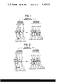
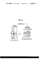
- the basic lens shape is such that the diverging lens group which is the forward group comprises, in order from the object side, a first member which is a negative meniscus lens component convex to the object side, a second member which is a positive lens component, a third member which is a negative lens component, and a fourth member which is a positive meniscus lens component convex to the object side, these four lens components being separate from one another, and an air chamber having a converging effect is formed between the second and the third member, and the third and fourth members are so disposed that the air chamber therebetween has a greater thickness than the center thickness of the third member.
- the converging lens group which is the rearward group comprises, in order from the object side, a fifth member which is a positive lens component, a sixth component which is a positive lens, a seventh member which is a positive meniscus lens component convex to the object side, an eighth member which is a negative lens component, and a ninth member which is a positive lens component, these five components being separate from one another.
- FIGS. 1 to 9 are cross-sectional views showing the lens arrangements according to Examples 1 to 9, respectively, of the present invention.
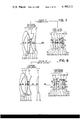
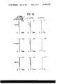
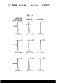
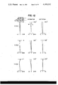
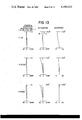
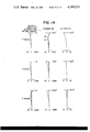
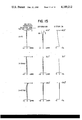
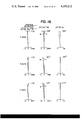
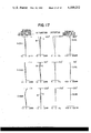
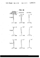
- FIGS. 10 to 18 are graphs illustrating various aberrations in Examples 1 to 9, respectively.
- R 5 represents the curvature radius of the surface of the negative lens component of the third member which faces the object side
- R 6 the curvature radius of the surface of the same lens component which faces the image side
- this negative lens component L 3 must satisfy the foregoing condition.
- the negative meniscus lens component of the first member L 1 and the negative lens component of the third member L 3 must satisfy the relation that 0.7 ⁇
- this condition is departed from, it will become difficult to well correct the curvature of the image plane at the short focal length side of the lens system.
- the air space D between the negative lens component of the third member L 3 and the positive meniscus lens of the fourth member L 4 is made greater than the center thickness of the third member L 3 and if the total focal length of the diverging lens group which is the forward group is f 1 , the following condition must be satisfied to thicken such diverging lens group and correct the variations both in spherical aberration and curvature of image field resulting from the variation in the focal length:
- the focal length of the positive meniscus lens L 4 which is the fourth member of the diverging lens group is f 14 .
- is useful to make the above condition (2) more effective and serves to play the auxiliary role for correcting the variations both in spherical aberration and curvature of image field. If the upper limit of this condition is exceeded, under-correction of the spherical aberration at the long focal length side will occur to bring about negative curvature of image field at the short focal length side. If the lower limit is exceeded, over-correction of the spherical aberration at the long focal length side will occur to bring about positive curvature of image field at the short focal length side.
- the converging lens group which is the rearward group is required to be of a great relative aperture due to the forward group being a diverging lens group, but when the zoom lens of this type is to be designed as compactly as possible, it is desirable that the forward principal plane be projected forwardly of the lens as in the telephoto type.
- the present invention employs a converging lens group which is approximate to the Sonnar type comprising the five components as already described.
- This converging group will hereinafter be referred to as Type I.
- the present invention has been successful in making compact a wide angle zoom lens having a construction characteristic to the Sonnar type in which the principal point of the lens system lies forwardly of the system and which permits a great aperture, and overcoming the tendency of the Petzval sum becoming negative.
- the refractive indices of the sixth member or the positive lens component L 6 and the seventh member or the positive meniscus lens component L 7 be less than 1.65 and the refractive index of the eighth member or the negative lens component L 8 be higher by 0.17 or more than said refractive indices.
- the power of the diverging lens group may be relatively intensified with respect to that of the converging lens group but in that case, the backward converging lens group must be made capable of withstanding a greater angle of view in terms of aberration. Therefore, the positive lens component which is the ninth member L 9 in the converging lens group which is closest to the image side may be divided into two positive lenses L 9a , L 9b , whereby there may be provided the effect of rendering the distortion to the positive and the freedom of correction of the curvature of image field and thus, it is possible to provide a zoom lens which can use at a wider angle of view, say, 81.6°.
- This converging group will hereinafter referred to as Type II.
- the two components namely, the positive lens component of the sixth member L 6 and the positive meniscus lens component of the seventh member L 7 which is convex to the object side, may be united together into a single positive meniscus lens L 67 which is convex to the object side, whereby it becomes possible to provide a zoom optical system covering a half angle of view of the order of 31°.
- This converging group will hereinafter be referred to as Type III.
- a single type of the diverging lens group is usable in common with three alternative types of the converging lens group. These may be classified as follows, for various examples which will further be described.
- the above-mentioned common diverging group forms the greatest feature and it is desirable that the focal lengths of the individual lens components of the diverging group satisfy the following conditions:
- f 1 represents the total focal length of the diverging lens group
- f 1i the focal lengths of the individual lens components in the diverging group
- suffix i the order of the lens components from the object side.
- Q 1i represents the shape factor of each lens component in the diverging group
- suffix i represents the order of each lens component from the object side
- Q is defined as
- r F and r R represent the curvature radii of the formost and rearmost surfaces, respectively, of each lens component.
- f 2 represents the total focal length of the converging group
- f 2i the focal length of each lens component in the converging group
- suffix i the order of each lens component from the object side.
- Q 2i represents the shape factor of each lens component in the converging group
- suffix i the order of each lens component from the object side.
- the zoom ratio is about 2.0 and F-number is of the order to 3.5 to 4.0
- Examples 1, 2 and 9 respectively cover an angle of view of 62° at the shortest focal length side
- Example 7 covers an angle of view of 74°
- the other examples are ultra-wide angle zoom lenses which cover 80° or more.
- the various aberrations are well corrected and especially, the distortion is so well corrected as it is comparable to or superior to the single focal length lens and the lens shape is compact.
- the air space between the two groups and accordingly, the entire shape become maximum during the shortest focal length condition. It may thus be said that the size of such two-group zoom lens system is smaller as the distance from the foremost lens surface to the back focal plane during the shortest focal length condition is smaller.
- the size of the lens system as a zoom lens must be compared with the focal length, the zoom ratio, F-number, etc. taken into account, and for reference, the ratio of the distance L from the foremost lens surface to the back focal plane during the shortest focal length condition to the shortest focal length fw will be shown with respect to each example.
- Example 1 is a basic form of the zoom lens system according to the present invention.
- any desired positive lens component in the converging lens group may be formed as a doublet to thereby facilitate the correction of the axial chromatic aberration and reduce the chromatic variation in spherical aberration at the longest focal length side, and herein such effects are attained in Example 2 wherein the fifth member of the positive lens component L 5 is a doublet.
- Numerical data in Examples 1 and 2 will be shown below, and the lens arrangement of these Examples in their shortest focal length condition are shown in FIGS. 1 and 2, while various aberrations in these Examples are illustrated in FIGS. 10 and 11.
- r 1 , r 2 , r 3 , . . . represent the curvature radii of the refracting surfaces of the lenses
- d 1 , d 2 , d 3 , . . . represent the center thickness of the lenses and the air spaces therebetween
- n 1 , n 2 , n 3 , . . . and ⁇ 1 , ⁇ 2 , ⁇ 3 , . . . represent the refractive indices and Abbe numbers of the lenses.
- r 1 , r 2 , r 3 , . . . represent the curvature radii of the refracting surfaces of the lenses
- d 1 , d 2 , d 3 , . . . represent the center thickness of the lenses and the air spaces therebetween
- n 1 , n 2 , n 3 , . . . and ⁇ 1 , ⁇ 2 , ⁇ 3 , . . . represent the refractive indices and Abbe numbers of the lenes.
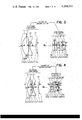
- Example 3 is substantially identical in lens arrangement to the Example 1, but as already noted, in the diverging group thereof, the Abbe numbers of glass for the diverging lens components are selected to greater values than those for the converging lens components to thereby sufficiently corrent even the high degrees of chromatic aberration such as the imbalance of the chromatic difference of magnification attributable to the angle of view and the mismatching of the image field curvature resulting from the chromatic difference, and the result is the provision of a zoom lens covering a wider angle of view.
- the numerical data of this Example will be shown below, and the lens arrangement thereof during the shortest focal length condition is shown in FIG. 3 while the various aberrations therein are illustrated in FIG. 12.
- r 1 , r 2 , r 3 , . . . represent the curvature radii of the refracting surfaces of the lenses
- d 1 , d 2 , d 3 , . . . represent the center thickness of the lenses and the air spaces therebetween
- n 1 , n 2 , n 3 , . . . and ⁇ 1 , ⁇ 2 , ⁇ 3 , . . . represent the refractive indices and Abbe number of the lenses.
- Example 4 is a basic form of the present invention in which the positive lens component L 9 which is the ninth member located closest to the image side in Example 1 is divided into two positive lenses L 9a , L 9b to thereby increase the angle of view.
- the positive lens component L 9 which is the ninth member located closest to the image side in Example 1 is divided into two positive lenses L 9a , L 9b to thereby increase the angle of view.
- the negative meniscus lens component L 1 which is the first member
- the negative lens component L 3 which is the third member
- the positive meniscus lens component L 4 which is the fourth member in the diverging lens group
- the negative lens component L 3 which is the third member is formed as a doublet to provide the effect of correcting such chromatic aberration.
- Examples 5 and 6 are the forms in which one of the two divided positive lens components L 9a in Example 4 which is closer to the object side is formed as a doublet and this positive lens is designed with a low refractive index while the negative lens is designed with a high refractive index, thereby well correcting the Petzval sum. Again in these Examples, the effect similar to that of Example 2 is further added.
- the numerical data of Examples 4, 5 and 6 will be shown below, and the lens arrangements of these Examples during their shortest focal length condition are shown in FIGS. 4, 5 and 6, while the various aberrations in these Examples are illustrated in FIGS. 13, 14 and 15.
- r 1 , r 2 , r 3 , . . . represent the curvature radii of the refracting surfaces of the lenses
- d 1 , d 2 , d 3 , . . . represent the center thickness of the lenses and the air spaces therebetween
- n 1 , n 2 , n 3 , . . . and ⁇ 1 , ⁇ 2 , ⁇ 3 , . . . represent the refractive indices and Abbe numbers of the lenses.
- r 1 , r 2 , r 3 , . . . represent the curvature radii of the refracting surfaces of the lenses
- d 1 , d 2 , d 3 , . . . represent the center thickness of the lenses and the air spaces therebetween
- n 1 , n 2 , n 3 , . . . and ⁇ 1 , ⁇ 2 , ⁇ 3 , . . . represent the refractive indices and Abbe number of the lenses.
- r 1 , r 2 , r 3 , . . . represent the curvature radii of the refracting surfaces of the lenses
- d 1 , d 2 , d 3 , . . . represent the center thickness of the lenses and the air spaces therebetween
- n 1 , n 2 , n 3 , . . . and ⁇ 1 , ⁇ 2 , ⁇ 3 , . . . represent the refractive indices and Abbe numbers of the lenses.
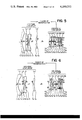
- Example 7 like Example 3, is a form in which contrivances and given to the Abbe numbers of the convergent and the divergent components in the diverging lens group to thereby sufficiently correct the high degrees of chromatic aberration.
- Example 8 is a form similar to Example 7 but which achieves a zoom lens covering a wider angle of view.
- r 1 , r 2 , r 3 , . . . represent the curvature radii of the refracting surfaces of the lenses
- d 1 , d 2 , d 3 , . . . represent the center thickness of the lenses and the air spaces therebetween
- n 1 , n 2 , n 3 , . . . and ⁇ 1 , ⁇ 2 , ⁇ 3 , . . . represent the refractive indices and Abbe numbers of the lenses.
- Example 9 is a modification of the basic form of Example 4, in which the sixth member or the positive lens component and the seventh member or the positive meniscus lens component which is convex to the object side are coupled to a single positive meniscus lens component which is convex to the object side, to provide the converging lens group by five components, thereby providing compactness of the entire lens system.
- Numerical data of this Example will be shown below, and the lens arrangement of this Example during the shortest focal length condition is shown in FIG. 9, while the aberrations in this Example are illustrated in FIG. 18.
- r 1 , r 2 , r 3 , . . . represent the curvature radii of the refracting surfaces of the lenses
- d 1 , d 2 , d 3 , . . . represent the center thickness of the lenses and the air spaces therebetween
- n 1 , n 2 , n 3 , . . . and ⁇ 1 , ⁇ 2 , ⁇ 3 , . . . represent the refractive indices and Abbe numbers of the lenses.
Landscapes
- Physics & Mathematics (AREA)
- General Physics & Mathematics (AREA)
- Optics & Photonics (AREA)
- Lenses (AREA)
Applications Claiming Priority (4)
| Application Number | Priority Date | Filing Date | Title |
|---|---|---|---|
| JP51050792A JPS594681B2 (ja) | 1976-05-06 | 1976-05-06 | 広角ズ−ムレンズ系 |
| JP51/50792 | 1976-05-06 | ||
| JP51/127766 | 1976-10-26 | ||
| JP51127766A JPS594684B2 (ja) | 1976-10-26 | 1976-10-26 | 高性能広角ズ−ムレンズ系 |
Publications (1)
| Publication Number | Publication Date |
|---|---|
| US4189212A true US4189212A (en) | 1980-02-19 |
Family
ID=26391264
Family Applications (1)
| Application Number | Title | Priority Date | Filing Date |
|---|---|---|---|
| US05/793,593 Expired - Lifetime US4189212A (en) | 1976-05-06 | 1977-05-04 | Wide angle zoom lens system |
Country Status (2)
| Country | Link |
|---|---|
| US (1) | US4189212A (de) |
| DE (1) | DE2720443C3 (de) |
Cited By (10)
| Publication number | Priority date | Publication date | Assignee | Title |
|---|---|---|---|---|
| US4266860A (en) * | 1978-09-08 | 1981-05-12 | Nippon Kogaku K.K. | Wide angle zoom lens system having shortened closeup focal length |
| US4294521A (en) * | 1978-09-01 | 1981-10-13 | Fuji Photo Optical Co., Ltd. | Rear stop type zoom lens |
| US4304466A (en) * | 1978-09-11 | 1981-12-08 | Vivitar Corporation | Zoom lens |
| FR2742237A1 (fr) * | 1995-12-12 | 1997-06-13 | Asahi Optical Co Ltd | Objectif zoom super grand angle |
| US20040174578A1 (en) * | 2002-04-03 | 2004-09-09 | Inphase Technologies, Inc. | Holographic storage lenses |
| US20080106801A1 (en) * | 2006-11-02 | 2008-05-08 | Young Optics Inc. | Zoom lens |
| US20110085246A1 (en) * | 2009-10-14 | 2011-04-14 | Samsung Electronics Co., Ltd. | Zoom lens and image pickup device having the same |
| CN103765283A (zh) * | 2011-08-29 | 2014-04-30 | 富士胶片株式会社 | 变焦镜头和成像设备 |
| US20140168788A1 (en) * | 2011-08-29 | 2014-06-19 | Fujifilm Corporation | Zoom lens and imaging apparatus |
| CN114815197A (zh) * | 2022-06-29 | 2022-07-29 | 江西晶超光学有限公司 | 光学系统、镜头模组和电子设备 |
Families Citing this family (1)
| Publication number | Priority date | Publication date | Assignee | Title |
|---|---|---|---|---|
| JPS57190917A (en) * | 1981-05-20 | 1982-11-24 | Canon Inc | Superwide-angle zoom lens |
Citations (3)
| Publication number | Priority date | Publication date | Assignee | Title |
|---|---|---|---|---|
| US3848969A (en) * | 1972-04-18 | 1974-11-19 | Canon Kk | A short physical length zoom lens |
| DE2625058A1 (de) * | 1975-06-06 | 1976-12-16 | Canon Kk | Zoom-objektiv |
| DE2640486A1 (de) * | 1975-09-08 | 1977-03-10 | Canon Kk | Linsensystem mit veraenderbarer vergroesserung |
-
1977
- 1977-05-04 US US05/793,593 patent/US4189212A/en not_active Expired - Lifetime
- 1977-05-06 DE DE2720443A patent/DE2720443C3/de not_active Expired
Patent Citations (3)
| Publication number | Priority date | Publication date | Assignee | Title |
|---|---|---|---|---|
| US3848969A (en) * | 1972-04-18 | 1974-11-19 | Canon Kk | A short physical length zoom lens |
| DE2625058A1 (de) * | 1975-06-06 | 1976-12-16 | Canon Kk | Zoom-objektiv |
| DE2640486A1 (de) * | 1975-09-08 | 1977-03-10 | Canon Kk | Linsensystem mit veraenderbarer vergroesserung |
Cited By (21)
| Publication number | Priority date | Publication date | Assignee | Title |
|---|---|---|---|---|
| US4294521A (en) * | 1978-09-01 | 1981-10-13 | Fuji Photo Optical Co., Ltd. | Rear stop type zoom lens |
| US4266860A (en) * | 1978-09-08 | 1981-05-12 | Nippon Kogaku K.K. | Wide angle zoom lens system having shortened closeup focal length |
| US4304466A (en) * | 1978-09-11 | 1981-12-08 | Vivitar Corporation | Zoom lens |
| FR2742237A1 (fr) * | 1995-12-12 | 1997-06-13 | Asahi Optical Co Ltd | Objectif zoom super grand angle |
| GB2308204A (en) * | 1995-12-12 | 1997-06-18 | Asahi Optical Co Ltd | Super wide angle zoom lens with negative first group |
| US5877901A (en) * | 1995-12-12 | 1999-03-02 | Asahi Kogaku Kogyo Kabushiki Kaisha | Super wide-angle zoom lens |
| GB2308204B (en) * | 1995-12-12 | 2000-04-26 | Asahi Optical Co Ltd | Super wide-angle zoom lens with negative first group |
| US20040174578A1 (en) * | 2002-04-03 | 2004-09-09 | Inphase Technologies, Inc. | Holographic storage lenses |
| US6885510B2 (en) * | 2002-04-03 | 2005-04-26 | Inphase Technologies, Inc. | Holographic storage lenses |
| US7405885B2 (en) | 2006-11-02 | 2008-07-29 | Young Optics Inc. | Zoom lens |
| US20080106801A1 (en) * | 2006-11-02 | 2008-05-08 | Young Optics Inc. | Zoom lens |
| US20110085246A1 (en) * | 2009-10-14 | 2011-04-14 | Samsung Electronics Co., Ltd. | Zoom lens and image pickup device having the same |
| US8045275B2 (en) * | 2009-10-14 | 2011-10-25 | Samsung Electronics Co., Ltd. | Zoom lens and image pickup device having the same |
| CN103765283A (zh) * | 2011-08-29 | 2014-04-30 | 富士胶片株式会社 | 变焦镜头和成像设备 |
| US20140153111A1 (en) * | 2011-08-29 | 2014-06-05 | Fujifilm Corporation | Zoom lens and imaging apparatus |
| US20140168788A1 (en) * | 2011-08-29 | 2014-06-19 | Fujifilm Corporation | Zoom lens and imaging apparatus |
| US9013800B2 (en) * | 2011-08-29 | 2015-04-21 | Fujifilm Corporation | Zoom lens and imaging apparatus |
| US9261685B2 (en) * | 2011-08-29 | 2016-02-16 | Fujifilm Corporation | Zoom lens and imaging apparatus |
| CN103765283B (zh) * | 2011-08-29 | 2016-03-30 | 富士胶片株式会社 | 变焦镜头和成像设备 |
| CN114815197A (zh) * | 2022-06-29 | 2022-07-29 | 江西晶超光学有限公司 | 光学系统、镜头模组和电子设备 |
| CN114815197B (zh) * | 2022-06-29 | 2022-10-21 | 江西晶超光学有限公司 | 光学系统、镜头模组和电子设备 |
Also Published As
| Publication number | Publication date |
|---|---|
| DE2720443A1 (de) | 1977-11-24 |
| DE2720443B2 (de) | 1980-02-07 |
| DE2720443C3 (de) | 1980-10-09 |
Similar Documents
| Publication | Publication Date | Title |
|---|---|---|
| US4999007A (en) | Vari-focal lens system | |
| US5069536A (en) | Zoom lens system | |
| US5196962A (en) | Vari-focal lens system | |
| US5793536A (en) | Zoom lens | |
| US4155629A (en) | Wide angle zoom lens system | |
| US4189212A (en) | Wide angle zoom lens system | |
| US4883346A (en) | Zoom lens system | |
| US4153338A (en) | Wide-angle zoom lens system | |
| JP3429554B2 (ja) | 変倍レンズ | |
| JPH0634885A (ja) | ズームレンズ | |
| US4789226A (en) | Zoom lens system | |
| JPH05241073A (ja) | ズームレンズ | |
| US5166828A (en) | Zoom lens system | |
| US5666233A (en) | Two-unit zoom lens system having a high zoom ratio | |
| US4641928A (en) | Four-group telephoto zoom lens | |
| JP3607958B2 (ja) | レトロフォーカス型レンズ | |
| US5132838A (en) | Keplerian zoom finder optical system | |
| JP3735909B2 (ja) | レトロフォーカス型レンズ | |
| US5703723A (en) | Optical system comprising graded refractive index lens element | |
| JP3369598B2 (ja) | 変倍レンズ | |
| US4364641A (en) | Wide angle zoom lens | |
| US5170292A (en) | Wide-angle zoom lens system | |
| JPH06294932A (ja) | ズームレンズ | |
| JPH10197793A (ja) | ズームレンズ | |
| US5479295A (en) | Compact zoom lens |
Legal Events
| Date | Code | Title | Description |
|---|---|---|---|
| AS | Assignment |
Owner name: NIKON CORPORATION, 2-3, MARUNOUCHI 3-CHOME, CHIYOD Free format text: CHANGE OF NAME;ASSIGNOR:NIPPON KOGAKU, K.K.;REEL/FRAME:004935/0584 |