US416229A - Elastic pump-rod - Google Patents
Elastic pump-rod Download PDFInfo
- Publication number
- US416229A US416229A US416229DA US416229A US 416229 A US416229 A US 416229A US 416229D A US416229D A US 416229DA US 416229 A US416229 A US 416229A
- Authority
- US
- United States
- Prior art keywords
- rod
- pump
- springs
- bolts
- lugs
- Prior art date
- Legal status (The legal status is an assumption and is not a legal conclusion. Google has not performed a legal analysis and makes no representation as to the accuracy of the status listed.)
- Expired - Lifetime
Links
- 238000010276 construction Methods 0.000 description 5
- 230000004048 modification Effects 0.000 description 3
- 238000012986 modification Methods 0.000 description 3
- XLYOFNOQVPJJNP-UHFFFAOYSA-N water Substances O XLYOFNOQVPJJNP-UHFFFAOYSA-N 0.000 description 3
- 230000006872 improvement Effects 0.000 description 2
- 229910000831 Steel Inorganic materials 0.000 description 1
- 230000009471 action Effects 0.000 description 1
- 230000009286 beneficial effect Effects 0.000 description 1
- 230000008859 change Effects 0.000 description 1
- 230000006835 compression Effects 0.000 description 1
- 238000007906 compression Methods 0.000 description 1
- 238000010168 coupling process Methods 0.000 description 1
- 238000005859 coupling reaction Methods 0.000 description 1
- 230000007246 mechanism Effects 0.000 description 1
- 230000001105 regulatory effect Effects 0.000 description 1
- 230000000284 resting effect Effects 0.000 description 1
- 239000010959 steel Substances 0.000 description 1
Images

Classifications
-
- F—MECHANICAL ENGINEERING; LIGHTING; HEATING; WEAPONS; BLASTING
- F16—ENGINEERING ELEMENTS AND UNITS; GENERAL MEASURES FOR PRODUCING AND MAINTAINING EFFECTIVE FUNCTIONING OF MACHINES OR INSTALLATIONS; THERMAL INSULATION IN GENERAL
- F16C—SHAFTS; FLEXIBLE SHAFTS; ELEMENTS OR CRANKSHAFT MECHANISMS; ROTARY BODIES OTHER THAN GEARING ELEMENTS; BEARINGS
- F16C7/00—Connecting-rods or like links pivoted at both ends; Construction of connecting-rod heads
- F16C7/04—Connecting-rods or like links pivoted at both ends; Construction of connecting-rod heads with elastic intermediate part of fluid cushion
-
- Y—GENERAL TAGGING OF NEW TECHNOLOGICAL DEVELOPMENTS; GENERAL TAGGING OF CROSS-SECTIONAL TECHNOLOGIES SPANNING OVER SEVERAL SECTIONS OF THE IPC; TECHNICAL SUBJECTS COVERED BY FORMER USPC CROSS-REFERENCE ART COLLECTIONS [XRACs] AND DIGESTS
- Y10—TECHNICAL SUBJECTS COVERED BY FORMER USPC
- Y10T—TECHNICAL SUBJECTS COVERED BY FORMER US CLASSIFICATION
- Y10T74/00—Machine element or mechanism
- Y10T74/21—Elements
- Y10T74/2142—Pitmans and connecting rods
- Y10T74/2144—Yieldable
- Y10T74/2146—Longitudinal springs
Definitions
- N PETERS Photo-Lithograph. Wznhinglnn. u. c.
- the object is to provide simple means for r 5 relieving both the pump and wind-wheel from sudden and excessive strains when the wheel is driven out of its accustomed speed or struck by a sudden gust of wind.
- a further object attained by my invention is that the pump may be operated by an unusually small amount of wind, due to the fact that the column of water in the pump or tubing is raised or started more gently by the yielding of the rod.
- a still further object is to prevent the breakage of the pump-couplings, jerking ot' the pump from its fastenings, and to dispense with the use of braces to hold the pump down in place.
- a still further object is to provide means for readily changing the tension to correspond with the depth of the well or of the forcingpower required, and also means for changing the spring mechanism or compensating for 5 any wear or permanent compression of the springs.
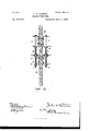
- Figure 1 is a longitudinal section through the adjacent ends of the rod-sections, showing the connected parts.
- Figs. 2 and 3 are modifications.
- a A represent sections of a pump-rod. To the upper section A brackets B are securely bolted. These are preferably four in number,
- each bolt to may extend through a flange of two brackets.
- brackets are placed adjacent to each other and provided with lugs 12, projecting at right angles to the rod-sections. Similar brackets B are seen red to the other section A of the pump-rod, and the lugs 12 of these brackets are in alignment with the lugs Z) of the brackets B. These lugs are provided with boltholes 0, and through them a pair of bolts D pass, so that their heads rest upon the upper lugs b and their lower ends extend some distance beyond the lugs Z).
- Sleeves E are mounted on the bolts between the lugs b and b, and they are preferably of suflicieut length to permit the rod-sections A A to rest normally ashort distance apart.
- the followers (I, mounted on bolts D below the lugs I), receive the ends of spiral springs F, which latter are mounted on the bolts.
- the tension of the springs is regulated by the nuts 6, and washers maybe placed between the lugs and followers in order to prevent lost motion to the reciprocating pump-rod without necessitating a change in the length of the latter.
- I may apply large coils of springs made of heavy steel.
- springs H are employed in place of the sleeves E in the former construction. Otherwise the two constructions are precisely the same. These springs are used when it is expedient to force water. For most farm wind-wheels these springs H are unnecessary.
Landscapes
- Engineering & Computer Science (AREA)
- General Engineering & Computer Science (AREA)
- Mechanical Engineering (AREA)
- Looms (AREA)
Description
(No Model.) 2 Sheets-Sheet 1. J. P. LOOMIS.
ELASTIC PUMP ROD.
No. 416.229. Patented Dec. 3, 1889.
N PETERS. Photo-Lithograph". Wznhinglnn. u. c.
(No Model.) 2 Sheets-Sheet 2.
J. F. LOOMIS.
ELASTIC PUMP ROD.
UNITED STATES PATENT OFFICE.
JOHN FAY LOOMIR, OF SHELBY, ASSIGNOR TO CHARLES A. ALTMANNSPER- GER, OF POTlAlVA'lTllAMIE COUNTY, AND ALICE M. LOOMIS, OF SHELBY ("OITNTY, IO\VA.
ELASTIC PUMP-ROD.
SPECIFICATION forming part of Letters Patent No. 416,229, dated December 3, 1889. Application filed August 28,1889. Serial No; 322,211. (No model.)
To all whom it may concern.- Be it known that I, JOHN FAY LOOMIS, of Shelby, in the county of Shelby and State of Iowa, have invented certain new and useful Improvements in Elastic Pump-Rods; and I do hereby declare the following to be a full, clear, and exact description of the invention, such as will enable others skilled in the art to which it appertains to make and use the same. My invention relates to an improvement in elastic pump-rods, designed more especially for extended pump-rods to which wind-wheels are attached.
The object is to provide simple means for r 5 relieving both the pump and wind-wheel from sudden and excessive strains when the wheel is driven out of its accustomed speed or struck by a sudden gust of wind.
A further object attained by my invention is that the pump may be operated by an unusually small amount of wind, due to the fact that the column of water in the pump or tubing is raised or started more gently by the yielding of the rod.
A still further object is to prevent the breakage of the pump-couplings, jerking ot' the pump from its fastenings, and to dispense with the use of braces to hold the pump down in place.
A still further object is to provide means for readily changing the tension to correspond with the depth of the well or of the forcingpower required, and also means for changing the spring mechanism or compensating for 5 any wear or permanent compression of the springs.
With these ends in view my invention consists in certain features of construction and combinations of parts, as will be hereinafter 40 described, and pointed out in the claims.
In the accompanying drawings, Figure 1 is a longitudinal section through the adjacent ends of the rod-sections, showing the connected parts. Figs. 2 and 3 are modifications.
A A represent sections of a pump-rod. To the upper section A brackets B are securely bolted. These are preferably four in number,
placed opposite each other, or, in other words, with two on one side of the rod and two on the opposite side, so that each bolt to may extend through a flange of two brackets. The
brackets are placed adjacent to each other and provided with lugs 12, projecting at right angles to the rod-sections. Similar brackets B are seen red to the other section A of the pump-rod, and the lugs 12 of these brackets are in alignment with the lugs Z) of the brackets B. These lugs are provided with boltholes 0, and through them a pair of bolts D pass, so that their heads rest upon the upper lugs b and their lower ends extend some distance beyond the lugs Z). Sleeves E are mounted on the bolts between the lugs b and b, and they are preferably of suflicieut length to permit the rod-sections A A to rest normally ashort distance apart.
The followers (I, mounted on bolts D below the lugs I), receive the ends of spiral springs F, which latter are mounted on the bolts. The tension of the springs is regulated by the nuts 6, and washers maybe placed between the lugs and followers in order to prevent lost motion to the reciprocating pump-rod without necessitating a change in the length of the latter. Also, it is well to mention that I may apply large coils of springs made of heavy steel. These parts, of course, are all susceptible of variation in accordance with the power exerted and required to be exerted.
In the modification shown in Fig. 2 springs H are employed in place of the sleeves E in the former construction. Otherwise the two constructions are precisely the same. These springs are used when it is expedient to force water. For most farm wind-wheels these springs H are unnecessary.
In the modification shown in Fig. 3 the bolts are lengthened, and springs F, similar to springs F, are resorted to, the usual followers being used to receive the ends of the springs. All these springs act with the upstroke of the pump-rod when a greater tension is required for very deep Wells. Thus all four springs are brought into action on the up stroke of the pump-rod and the upper two springs on the downstroke, providing water is to be forced.
In the construction. of my invention I reduce the parts to a minimum, cut down eX- pense, prevent unnecessary friction, and at the same time attain all the beneficial results herein set forth.
It is evident that slight changes might be resorted to in the form and arrangement of the several parts described without departing from the spirit and scope of my invention. Hence I do not wish to be limited to the precise construction herein set forth; but,
Having fully described my invention, what I claim as new, and desire to secure by Letters Patent, is-
1. The combination, with a sectional pumprod having projections thereon, of bolts extending loosely through said projections and spiral springs on the bolts outside of the projections, substantially as set forth.
2. The combination with a sectional pumprod having projections thereon, of bolts extending loosely through the projections and spiral springs on the ends of the bolts outside of the projections and also between the adjacentprojections on the two sections, substantially as set forth.
3. The combination, with a sectional pumprod having projections thereon, of bolts extending loosely through said projections, followers on said bolts, and spiral springs on the bolts outside the projections and having their ends resting in the followers, substantially as set forth.
In testimony whereof I have signed this specification in the presence of two subscribing witnesses.
JOHN FAY LOOMIS.
Witnesses C. G. SANFORD. CLINTON MORGAN.
Publications (1)
| Publication Number | Publication Date |
|---|---|
| US416229A true US416229A (en) | 1889-12-03 |
Family
ID=2485156
Family Applications (1)
| Application Number | Title | Priority Date | Filing Date |
|---|---|---|---|
| US416229D Expired - Lifetime US416229A (en) | Elastic pump-rod |
Country Status (1)
| Country | Link |
|---|---|
| US (1) | US416229A (en) |
Cited By (1)
| Publication number | Priority date | Publication date | Assignee | Title |
|---|---|---|---|---|
| US2528124A (en) * | 1945-12-01 | 1950-10-31 | Elliott Lee | Self-blowing whistle for locomotives |
-
0
- US US416229D patent/US416229A/en not_active Expired - Lifetime
Cited By (1)
| Publication number | Priority date | Publication date | Assignee | Title |
|---|---|---|---|---|
| US2528124A (en) * | 1945-12-01 | 1950-10-31 | Elliott Lee | Self-blowing whistle for locomotives |
Similar Documents
| Publication | Publication Date | Title |
|---|---|---|
| US416229A (en) | Elastic pump-rod | |
| US398078A (en) | peterson | |
| US323805A (en) | Deep-well pump | |
| US364423A (en) | Pitman or pump-rod | |
| US1349094A (en) | Pump-jack | |
| US450657A (en) | Compensating pump-spring | |
| US614681A (en) | Attachment for pumps | |
| US786854A (en) | Pumping-jack for oil-wells. | |
| US371895A (en) | Pitman or pump rod | |
| US593290A (en) | bennett | |
| US185937A (en) | Improvement in pump-handles | |
| US577445A (en) | Power-converter | |
| US300957A (en) | Thomas coubtney | |
| US406137A (en) | Pump attachment | |
| US216465A (en) | Improvement in hydraulic elevators | |
| US797672A (en) | Oil-well-pump attachment. | |
| US151310A (en) | Improvement in the modes of connecting pitmen to fly-wheels | |
| US739298A (en) | Pump attachment. | |
| US533768A (en) | Horse-power | |
| US1040305A (en) | Pump-operating device. | |
| US3109313A (en) | Pumping unit with spring connected walking beam | |
| US899872A (en) | Windmill-gearing. | |
| US1453417A (en) | Detachable hub for eccentrics | |
| US587525A (en) | Well-pumping power | |
| US736530A (en) | Windmill-pump stroke-regulator. |