US410514A - William gee - Google Patents
William gee Download PDFInfo
- Publication number
- US410514A US410514A US410514DA US410514A US 410514 A US410514 A US 410514A US 410514D A US410514D A US 410514DA US 410514 A US410514 A US 410514A
- Authority
- US
- United States
- Prior art keywords
- base
- stem
- casing
- jar
- sirup
- Prior art date
- Legal status (The legal status is an assumption and is not a legal conclusion. Google has not performed a legal analysis and makes no representation as to the accuracy of the status listed.)
- Expired - Lifetime
Links
- 239000000203 mixture Substances 0.000 description 18
- 230000036633 rest Effects 0.000 description 14
- 210000003739 Neck Anatomy 0.000 description 12
- 235000020357 syrup Nutrition 0.000 description 12
- 108060007338 SDHAF4 Proteins 0.000 description 10
- 238000010276 construction Methods 0.000 description 10
- 239000002184 metal Substances 0.000 description 10
- 229910052751 metal Inorganic materials 0.000 description 10
- 230000000284 resting Effects 0.000 description 10
- 210000000614 Ribs Anatomy 0.000 description 8
- 241000726123 Acanthurus Species 0.000 description 6
- 238000005266 casting Methods 0.000 description 6
- 230000005494 condensation Effects 0.000 description 6
- 238000009833 condensation Methods 0.000 description 6
- 238000007599 discharging Methods 0.000 description 6
- 239000011521 glass Substances 0.000 description 6
- XLYOFNOQVPJJNP-UHFFFAOYSA-N water Substances O XLYOFNOQVPJJNP-UHFFFAOYSA-N 0.000 description 6
- BVKZGUZCCUSVTD-UHFFFAOYSA-N Carbonic acid Chemical compound OC(O)=O BVKZGUZCCUSVTD-UHFFFAOYSA-N 0.000 description 4
- 210000002445 Nipples Anatomy 0.000 description 4
- PXHVJJICTQNCMI-UHFFFAOYSA-N nickel Chemical compound [Ni] PXHVJJICTQNCMI-UHFFFAOYSA-N 0.000 description 4
- 230000000630 rising Effects 0.000 description 4
- 206010022114 Injury Diseases 0.000 description 2
- 238000001816 cooling Methods 0.000 description 2
- 230000005484 gravity Effects 0.000 description 2
- 239000005457 ice water Substances 0.000 description 2
- 229910052500 inorganic mineral Inorganic materials 0.000 description 2
- 239000010985 leather Substances 0.000 description 2
- 239000004579 marble Substances 0.000 description 2
- 239000000463 material Substances 0.000 description 2
- 238000002844 melting Methods 0.000 description 2
- 239000011707 mineral Substances 0.000 description 2
- 230000004048 modification Effects 0.000 description 2
- 238000006011 modification reaction Methods 0.000 description 2
- 229910052759 nickel Inorganic materials 0.000 description 2
- 230000002093 peripheral Effects 0.000 description 2
- 229910052709 silver Inorganic materials 0.000 description 2
- 239000004332 silver Substances 0.000 description 2
- 239000002351 wastewater Substances 0.000 description 2
- 239000003643 water by type Substances 0.000 description 2
Images

Classifications
-
- B—PERFORMING OPERATIONS; TRANSPORTING
- B67—OPENING, CLOSING OR CLEANING BOTTLES, JARS OR SIMILAR CONTAINERS; LIQUID HANDLING
- B67D—DISPENSING, DELIVERING OR TRANSFERRING LIQUIDS, NOT OTHERWISE PROVIDED FOR
- B67D1/00—Apparatus or devices for dispensing beverages on draught
- B67D1/08—Details
- B67D1/0857—Cooling arrangements
- B67D1/0858—Cooling arrangements using compression systems
- B67D1/0861—Cooling arrangements using compression systems the evaporator acting through an intermediate heat transfer means
- B67D1/0865—Cooling arrangements using compression systems the evaporator acting through an intermediate heat transfer means by circulating a cooling fluid along beverage supply lines, e.g. pythons
- B67D1/0867—Cooling arrangements using compression systems the evaporator acting through an intermediate heat transfer means by circulating a cooling fluid along beverage supply lines, e.g. pythons the cooling fluid being a liquid
-
- B—PERFORMING OPERATIONS; TRANSPORTING
- B67—OPENING, CLOSING OR CLEANING BOTTLES, JARS OR SIMILAR CONTAINERS; LIQUID HANDLING
- B67D—DISPENSING, DELIVERING OR TRANSFERRING LIQUIDS, NOT OTHERWISE PROVIDED FOR
- B67D3/00—Apparatus or devices for controlling flow of liquids under gravity from storage containers for dispensing purposes
- B67D3/0054—Mounting or arrangements of dispensing apparatus in shops or bar counters
-
- B—PERFORMING OPERATIONS; TRANSPORTING
- B67—OPENING, CLOSING OR CLEANING BOTTLES, JARS OR SIMILAR CONTAINERS; LIQUID HANDLING
- B67D—DISPENSING, DELIVERING OR TRANSFERRING LIQUIDS, NOT OTHERWISE PROVIDED FOR
- B67D3/00—Apparatus or devices for controlling flow of liquids under gravity from storage containers for dispensing purposes
- B67D3/0009—Apparatus or devices for controlling flow of liquids under gravity from storage containers for dispensing purposes provided with cooling arrangements
-
- B—PERFORMING OPERATIONS; TRANSPORTING
- B67—OPENING, CLOSING OR CLEANING BOTTLES, JARS OR SIMILAR CONTAINERS; LIQUID HANDLING
- B67D—DISPENSING, DELIVERING OR TRANSFERRING LIQUIDS, NOT OTHERWISE PROVIDED FOR
- B67D3/00—Apparatus or devices for controlling flow of liquids under gravity from storage containers for dispensing purposes
- B67D3/0058—Details
- B67D3/008—Supports
- B67D3/0083—Supports for the liquid container
- B67D3/0087—Supports for the liquid container the beverage container being stored in a rack or shelf
-
- Y—GENERAL TAGGING OF NEW TECHNOLOGICAL DEVELOPMENTS; GENERAL TAGGING OF CROSS-SECTIONAL TECHNOLOGIES SPANNING OVER SEVERAL SECTIONS OF THE IPC; TECHNICAL SUBJECTS COVERED BY FORMER USPC CROSS-REFERENCE ART COLLECTIONS [XRACs] AND DIGESTS
- Y10—TECHNICAL SUBJECTS COVERED BY FORMER USPC
- Y10T—TECHNICAL SUBJECTS COVERED BY FORMER US CLASSIFICATION
- Y10T137/00—Fluid handling
- Y10T137/4673—Plural tanks or compartments with parallel flow
- Y10T137/474—With housings, supports or stacking arrangements
Definitions
- My invention relates to apparatus for dispensing effervescing drinks at retail, such as soda and mineral waters.
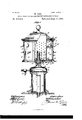
- Figure 1 is a sectional elevation showing an entire apparatus constructed in accordance Serial No. 311,848. (No model.)
- Fig. 2 is a horizontal section in the line co m
- Fig. 3 is a sectional plan view of the siruping apparatus.
- Fig. at is a detail View of one of the supporting columns or brackets removed from the siruping apparatus.
- Fig. 5 is a detail section of the lower part of one of the sirup-jars.
- Fig. 6 is a view of a sirup-j ar, showing a modified construction.
- the reference-numeral 1 denotes the marble or other shelf, counter, or support upon which the apparatus is placed.
- a base 2 having a central depending stem or nipple 3, which passes down through an openingin the counter and serves as a discharge for waste water.
- a flange 4 Surrounding the base 2 is a flange 4, within which is inserted the base of the cylindrical body 5, which is formed of sheet metal and provided with a double wall forming an annular dead-air space, which prevents the rapid conduction of the reduced temperature within or the higher temperature outside.
- the body portion is provided with a door 6, having a similar construction for the introduction of the ice, and a shield 7 is attached to its inner wall to protect the pipe from injury when the ice is thrown in.
- a cap 9 formed preferably of cast metal and provided with a ring 10, which supports one or more faucets 12, connected to the pipes emerging from the shield 7.
- This cap is held in place by tie-rods 13, passing up through the base 2 and through inwardly-projecting lugs 14 on the cap, nuts being turned on the ends of said rods above the lugs.
- a washer 15, of leather, rubber, or other suitable material, is slipped upon each tie-rod and lies between its head and the base 2, thereby forming a tight joint and preventing leakage through the openings made for the tie-rods.
- a cover 16 Upon the ring 10 is placed a cover 16, having a threaded flange 17 screwed within the ring.
- a seat 18 Upon the elevated central portion of this cover is formed a seat 18, having a central vertical stem or pivot 19, and provided below the base of the latter with a circumferential cup-shaped flange 20, apertures 21 being formed in the metal of the seat leading from the inner and lower parts of the cup to the inside of the cover, where they discharge into a diverting-passage 22, having its discharge end adjacent to the inner face of the cover.
- the nipple or stem 3 is threaded and receives a nut 23, which is turned up against the lower face of the counter.
- a surrounding and projecting foot-plate 24 is also formed upon the base of the body portion' and extended to rest on the counter at a little distance from the base 2, inclosing an air-space 25.
- the siruping apparatus which is contained within a casing of circular form having a base 26, provided with a central buttress27, in which is mount-ed a socket 28, the stem 19 passing through an opening in the buttress 27 and lying in the socket. Openings 29 are formed in the base at suit-able intervals surrounding the buttress 27, for the discharge of the water formed by melting ice and condensation, said openings discharging into the cup 20.
- the base 26 is formed preferably of a single casting provided with a hanging circumferential flange 30.
- a circular wall 31 having perforations 32, and rising to a suitable height to form a central ice -chamber.
- the annular space outside this wall is inclosed in the following manner: Surrounding the base is a pcripheral channel 33, and rising from said base at suitable intervals are columns or brackets 34, having substantially a T shape in cross-section, the central arm thereof projecting inward or toward the center.
- each column At the 'bottom and top of each column are formed horizontal plates 35, through which pass bolts or screws firmly connecting said columns to the base 26, the arrangement being such that the flat-vertical plate of each column is flush with the inner wall of the channel At their upper ends they are attached to a horizontal flange 36, which projects from the inner wall 31, and is provided with openings 37,'formed between the radial lines drawn from the center through each column.
- the top is covered by an annular cap 38, having double walls inclosingadead-air space.
- This cap is provided with an inwardly-projecting flange 39, which rests upon the top of the wall 31, while the periphery is seated in recesses 40, formed in the outer faces of the columns 34 at. their top.
- each panel is formed or mounted a lift45, which also serves to display the name of the sirup contained by the jar within.
- Each sirup-jar is preferably of the form shown in Fig. 3, whereby it nearly fills the space within which it lies and affords storage to the required quantity of sirup.
- Each jar is provided with a neck or top 46, which is externally threaded, and the jar being inverted when mounted upon the panel 41 this neck projects downward and through an opening 47 in the base 26, said opening beingsurrounded by a circular flange 48 to prevent the escape of water formed by condensation.
- a cap 49 within which is placed a glass valveseat 50, which is held by the cap closely against the open end of the neck.
- valve-seat engages a cone-shaped plug-valve 51, having a rubber facing 52 and carried by a stem 53, which rises within the jar and projects above its inverted bottom, which is formed of two unequal pieces of glass or metal 54 and 55, each having a half socket or bearing 56 for the valve-stem. Both of the parts forming the bottom of the jar may be removed for cleansing purposes.
- valve-stem 53 Upon the project-int end of the valve-stem 53 is formed a screw-thread, and a weight 57 is turned thereon, by the gravity of which the valve is seated. It is lifted by alever 58,having an angle or crook, whereby, when inserted through an aperture 59 in the panel, said lever requires no fulcrum-pin, but rests upon the edge of the opening in which it lies.
- the weight end of the lever is forked and embraces the valve-stem 53 below the weight 57.
- This weight being capable of adjustment.
- the power end of the lever may be raised to the proper point to enable it to have the desired operation, and in like manner a uniform and compensating adjustment may be given to all the levers, whereby the external appearance of the apparatus is much improved.
- the ice-chamber of the sirup apparatus is closed by a cover 60, also provided with a dead-air space. This cover rests directly upon the flange 39 of the annular cap 38. Openings 61 are formed in the inner wall 31, next to the base on which it rests, to allow the water of condensation to fiow to the discharge-openings 29. i
- the sirup-jars may be filled or inspected by simply tilting the panelsone at a time outward. This is effected by taking hold of the lift 45 and drawing the panel outward, whereupon the top swings toward the operator, the panel turning upon its lower edge, which lies in the channel 33. In this manner the jar is exposed without removing the cap or cover. I may, however, make the panels ICO a rigid portion of the frame or casing, and in this case the jars would be removed by taking off the cover, inserting the hand, removing the inverted bottom part 54 of the jar, and allowing the valve-stem to swing inward. The lever is then withdrawn from its aperture, and the jar may then be taken out.
- the casing containing the sirup apparatus may be round, polygonal, or square, without substantial modification of my invention in other particulars, and my invention may be applied to an immovable casing, wherein all the panels are arranged to form a continuous straight or curved front.
- the panels may be plated with silver or nickel, or otherwise ornamented in any suitable manner. They may be formed, also, of metal or other materialsuch as tilingpainted or decorated and inclosed in a metallic frame which sup ports the jar, and which may be plated.
- the cover 16 and seat 1S,with its cup-flange 20 and stem 19, are all cast in a single piece.
- jars which contain the sirup ribs 62 may be molded upon their outer faces in place of the grooves 46, and these ribs will lie between the flanges or tangs 42 and the panels When these ribs are substituted for I the grooves, lugs will be formed upon their ends to engage with and rest upon the upper ends of said flanges in order to throw the weight of the jar upon the panel.
- Vhat I claim is 1.
- a container having an icechamber in which the coils are arranged of a supporting cap or cover having a seat, a stem or spindle, and a cup-flange, all formed in one casting, and a rotating siruping apparatus contained in a casing pivotally mounted upon said seat and stem, substantially as described.
- an apparatus for dispensing effervescing drinks the combination, with an icecontainer in which the pipe-coils are arranged, of a cap or cover having a seat, a stem or spindle, and a flange, all formed of a single integral casting, a siruping apparatus contained in a casing pivotally mounted upon said stem and seat and haying openings in its base discharging into the cup-flange, and thence through openings in the seat into or upon a diverting-plate which conducts the drip to the inner face of the container, substantially as described.
- a siruping apparatus contained within a casing or chamber inclosed in front by a series of panels resting at their lower ends within a circumferential rib or flange, and upon the inner faces of which the sirupjars are detachably mounted, substantially as described.
- the combination with a casing, of a series of separate panels inclosing its front, each panel having its lower edge lying in a channel in the base of the casing, a series of inverted sirup-jars detachably mounted upon the inner faces of said panels and having valves carried by stems projecting through their inverted bottoms,and weights adj u stably mounted on the projecting ends of the valvestems, and actuating-levers inserted through openings in the panels and engaging the valve-stems beneath said weights, substantially as described.
- the combination with a casing, of a series of separate panels inclosing its front, a series of inverted sirup-jars detachably mounted on the inner faces of said panels, their necks projecting through openings in the base or floor of said chamber, a series of valves carried by stems which lie within and project above the inverted bottoms of the jars, each bottom being formed of two removable parts, each part having a half socket or bearing for the valve-stem, weights screwed upon the threaded projecting ends of the valve-stems, and a series of levers inserted through openings in the panels and resting upon the edges of said openings, said levers engaging the valve-stems beneath the weights, substantially as described.
- a sirup-jar having grooves in its body engaging flanges on the inner face of said panel, by which the jar is entirely supported, a screw-cap containing a valve-seat and turned upon the inverted neck of the jar, which projects through an opening in the base of the casing, a rubber-faced valve engaging said seat and mounted on a stem passing through the removable two-part bottom of the inverted jar, a weight turned upon the threaded projecting end of said stem, and a lever inserted in an opening in the panel and engaging the stem below the weight, substantially as described.
- a casing for the siruping apparatus having a circular base provided with a peripheral channel and having at intervals a series of columns or brackets arranged within said channel and connected by screws or rivets to the base and to a sectional flange above, and a series of panels having their lower ends resting in said channel and their vertical edges overlying the outer faces of ported by the container, substantially as de- 10.
Landscapes
- Engineering & Computer Science (AREA)
- Mechanical Engineering (AREA)
- Physics & Mathematics (AREA)
- Thermal Sciences (AREA)
- Devices For Dispensing Beverages (AREA)
Description
(No Model.) 2 Sheets-Sheet 1. W. GEE. APPARATUS FOR DISPENSING EFFERVESGING DRINKS.
No. 410,514. Patented Sept. 3, 1889.
IIII A N. PETERS. PholoL'mognphur. Waahingtan. a, c.
(No Model.) 2 Sheets-Sheet 2. W. GEE. APPARATUS FOR DISPENSING EFFERVESGING DRINKS.
Patented Sept. 3, 1889.
fizlz'am 6 66,
N. PETERS. Phmmmn m Wnmngfiom Li. c.
UNITED. STATES PATENT OFFICE.
WILLIAM GEE, OF NEW YORK, N. Y.
APPARATUS FOR DISPENSING EFFERVESCING DRINKS.
SP'EGIFICATION forming part of Letters Patent No. 410,514, dated September 3, 1889.
Application filed May 23, 1889.
To all whom it may concern.-
Be it known that I, \VILLIAM GEE, a citizen of the United States, residing at New York, in the county of New York and State of New York, have invented new and useful Improvements in Apparatus for Dispensing Effervescing Drinks, of which the following is a specification.
My invention relates to apparatus for dispensing effervescing drinks at retail, such as soda and mineral waters.
It is my purpose to provide a simple, convenient, and ornamental structure, forming a container for the ice and pipe-coils and surmounted by a cap supporting the faucets, said cap forming the pivotal seat for a revolving siruping apparatus having a central ice-chamber, from which the ice-water is discharged upon the inner wall of the ice-chamber in the container below, whence it is carried off by any suitable waste-pipe.
It is my purpose, also, to provide simple means whereby the valves of the sirup-jars may be readily operated, the construction being such as to permit a uniform and compensating adjustment of the parts and allow their easy removal and restoration to place, the entire sirup-casing being also rendered removable and separable to permit its thorough cleansing.
It is one purpose of my invention, also, to provide a novel and simple construction and combination of parts, whereby any one of the sirup-jars may be removed from the casing in which it is supported without uncovering said casing, and whereby, also, it may be refilled from its bottom, which is normally inverted and so constructed as to provide a separable bearing for the valve-stem.
It is my purpose, finally, to simplify and improve the construction and operation of apparatus of this class to render it convenient, compact, and of ornamental proportions and appearance, and to adapt the parts to eifect this cooling of the soda and of the sirups rapidly and economically, while the apparatus as a whole shall be so organized that it occupies a comparatively small space and may be constructed at a considerably reduced cost.
Referring to the accompanying drawings, Figure 1 is a sectional elevation showing an entire apparatus constructed in accordance Serial No. 311,848. (No model.)
with my invention. Fig. 2 is a horizontal section in the line co m, Fig. 1. Fig. 3 is a sectional plan view of the siruping apparatus. Fig. at is a detail View of one of the supporting columns or brackets removed from the siruping apparatus. Fig. 5 isa detail section of the lower part of one of the sirup-jars. Fig. 6 is a view of a sirup-j ar, showing a modified construction.
In the drawings, the reference-numeral 1 denotes the marble or other shelf, counter, or support upon which the apparatus is placed. Upon this support rests a base 2, having a central depending stem or nipple 3, which passes down through an openingin the counter and serves as a discharge for waste water. Surrounding the base 2 is a flange 4, within which is inserted the base of the cylindrical body 5, which is formed of sheet metal and provided with a double wall forming an annular dead-air space, which prevents the rapid conduction of the reduced temperature within or the higher temperature outside. The body portion is provided with a door 6, having a similar construction for the introduction of the ice, and a shield 7 is attached to its inner wall to protect the pipe from injury when the ice is thrown in.
Upon the upper end of the cylindrical body rests a cap 9, formed preferably of cast metal and provided with a ring 10, which supports one or more faucets 12, connected to the pipes emerging from the shield 7. This cap is held in place by tie-rods 13, passing up through the base 2 and through inwardly-projecting lugs 14 on the cap, nuts being turned on the ends of said rods above the lugs. A washer 15, of leather, rubber, or other suitable material, is slipped upon each tie-rod and lies between its head and the base 2, thereby forming a tight joint and preventing leakage through the openings made for the tie-rods.
Upon the ring 10 is placed a cover 16, having a threaded flange 17 screwed within the ring. Upon the elevated central portion of this cover is formed a seat 18, having a central vertical stem or pivot 19, and provided below the base of the latter with a circumferential cup-shaped flange 20, apertures 21 being formed in the metal of the seat leading from the inner and lower parts of the cup to the inside of the cover, where they discharge into a diverting-passage 22, having its discharge end adjacent to the inner face of the cover.
In order to firmly connect the base 2 and the parts mounted thereon firmly to the counter, the nipple or stem 3 is threaded and receives a nut 23, which is turned up against the lower face of the counter. A surrounding and projecting foot-plate 24 is also formed upon the base of the body portion' and extended to rest on the counter at a little distance from the base 2, inclosing an air-space 25.
Upon the seat 18 rests the siruping apparatus, which is contained within a casing of circular form having a base 26, provided with a central buttress27, in which is mount-ed a socket 28, the stem 19 passing through an opening in the buttress 27 and lying in the socket. Openings 29 are formed in the base at suit-able intervals surrounding the buttress 27, for the discharge of the water formed by melting ice and condensation, said openings discharging into the cup 20. q
The base 26 is formed preferably of a single casting provided with a hanging circumferential flange 30. Upon this base, at a point between its axial center and its periphery, is placed a circular wall 31, having perforations 32, and rising to a suitable height to form a central ice -chamber. The annular space outside this wall is inclosed in the following manner: Surrounding the base is a pcripheral channel 33, and rising from said base at suitable intervals are columns or brackets 34, having substantially a T shape in cross-section, the central arm thereof projecting inward or toward the center. At the 'bottom and top of each column are formed horizontal plates 35, through which pass bolts or screws firmly connecting said columns to the base 26, the arrangement being such that the flat-vertical plate of each column is flush with the inner wall of the channel At their upper ends they are attached to a horizontal flange 36, which projects from the inner wall 31, and is provided with openings 37,'formed between the radial lines drawn from the center through each column. The top is covered by an annular cap 38, having double walls inclosingadead-air space. This cap is provided with an inwardly-projecting flange 39, which rests upon the top of the wall 31, while the periphery is seated in recesses 40, formed in the outer faces of the columns 34 at. their top.
' The spaces between the several columns or brackets 34 are closedby panels 41, which have their lower edges placed in the channel 33, while their upper edges lie under that portion of the edge of the cap 38 which projects outward from the recesses 40 in the columns. From the inner face of each panel, near its vertical edges, project flanges or tangs 42, which extend inward and are then bent toward each other. These flanges engage grooves 43, formed in the glass sirup-jar 44,
but terminating a short distance from its invertedbottom, thus enabling said flanges to support the entire weight of the jar by which the panel is held closely and firmly in position. Upon the outer face of each panel is formed or mounted a lift45, which also serves to display the name of the sirup contained by the jar within.
Each sirup-jar .is preferably of the form shown in Fig. 3, whereby it nearly fills the space within which it lies and affords storage to the required quantity of sirup. Each jar is provided with a neck or top 46, which is externally threaded, and the jar being inverted when mounted upon the panel 41 this neck projects downward and through an opening 47 in the base 26, said opening beingsurrounded by a circular flange 48 to prevent the escape of water formed by condensation. Upon the projecting neck is screwed a cap 49, within which is placed a glass valveseat 50, which is held by the cap closely against the open end of the neck. With this valve-seat engages a cone-shaped plug-valve 51, having a rubber facing 52 and carried by a stem 53, which rises within the jar and projects above its inverted bottom, which is formed of two unequal pieces of glass or metal 54 and 55, each having a half socket or bearing 56 for the valve-stem. Both of the parts forming the bottom of the jar may be removed for cleansing purposes.
Upon the project-int end of the valve-stem 53 is formed a screw-thread, and a weight 57 is turned thereon, by the gravity of which the valve is seated. It is lifted by alever 58,having an angle or crook, whereby, when inserted through an aperture 59 in the panel, said lever requires no fulcrum-pin, but rests upon the edge of the opening in which it lies.
The weight end of the lever is forked and embraces the valve-stem 53 below the weight 57.
This weight being capable of adjustment.
upon the stem, the power end of the lever may be raised to the proper point to enable it to have the desired operation, and in like manner a uniform and compensating adjustment may be given to all the levers, whereby the external appearance of the apparatus is much improved.
The ice-chamber of the sirup apparatus is closed by a cover 60, also provided with a dead-air space. This cover rests directly upon the flange 39 of the annular cap 38. Openings 61 are formed in the inner wall 31, next to the base on which it rests, to allow the water of condensation to fiow to the discharge-openings 29. i
The sirup-jars may be filled or inspected by simply tilting the panelsone at a time outward. This is effected by taking hold of the lift 45 and drawing the panel outward, whereupon the top swings toward the operator, the panel turning upon its lower edge, which lies in the channel 33. In this manner the jar is exposed without removing the cap or cover. I may, however, make the panels ICO a rigid portion of the frame or casing, and in this case the jars would be removed by taking off the cover, inserting the hand, removing the inverted bottom part 54 of the jar, and allowing the valve-stem to swing inward. The lever is then withdrawn from its aperture, and the jar may then be taken out.
The casing containing the sirup apparatus may be round, polygonal, or square, without substantial modification of my invention in other particulars, and my invention may be applied to an immovable casing, wherein all the panels are arranged to form a continuous straight or curved front.- The panels may be plated with silver or nickel, or otherwise ornamented in any suitable manner. They may be formed, also, of metal or other materialsuch as tilingpainted or decorated and inclosed in a metallic frame which sup ports the jar, and which may be plated.
The cover 16 and seat 1S,with its cup-flange 20 and stem 19, are all cast in a single piece.
In forming the jars which contain the sirup ribs 62 may be molded upon their outer faces in place of the grooves 46, and these ribs will lie between the flanges or tangs 42 and the panels When these ribs are substituted for I the grooves, lugs will be formed upon their ends to engage with and rest upon the upper ends of said flanges in order to throw the weight of the jar upon the panel.
Vhat I claim is 1. In apparatus for dispensing effervescing drinks, the combination, with a container having an icechamber in which the coils are arranged, of a supporting cap or cover having a seat, a stem or spindle, and a cup-flange, all formed in one casting, and a rotating siruping apparatus contained in a casing pivotally mounted upon said seat and stem, substantially as described.
2. In an apparatus for dispensing effervescing drinks, the combination, with an icecontainer in which the pipe-coils are arranged, of a cap or cover having a seat, a stem or spindle, and a flange, all formed of a single integral casting, a siruping apparatus contained in a casing pivotally mounted upon said stem and seat and haying openings in its base discharging into the cup-flange, and thence through openings in the seat into or upon a diverting-plate which conducts the drip to the inner face of the container, substantially as described.
3. In an apparatus for discharging effervescing drinks, a siruping apparatus contained within a casing or chamber inclosed in front by a series of panels resting at their lower ends within a circumferential rib or flange, and upon the inner faces of which the sirupjars are detachably mounted, substantially as described.
4. In an apparatus for dispensing effervescin g drinks, the combination,with the casing, of a series of separate panels resting at their lower ends within a channel on the base of the casing, each panel being provided on its interior face with flanges or tangs, and sirupjars having grooves terminating at a short distance from their inverted bottom, and in which the flanges lie, substantially as described.
5. In apparatus for dispensing effervescing drinks, the combination, with a casing, of a series of separate panels inclosing its front, each panel having its lower edge lying in a channel in the base of the casing, a series of inverted sirup-jars detachably mounted upon the inner faces of said panels and having valves carried by stems projecting through their inverted bottoms,and weights adj u stably mounted on the projecting ends of the valvestems, and actuating-levers inserted through openings in the panels and engaging the valve-stems beneath said weights, substantially as described.
6. In apparatus for dispensing effervescing drinks, the combination, with a casing, of a series of separate panels inclosing its front, a series of inverted sirup-jars detachably mounted on the inner faces of said panels, their necks projecting through openings in the base or floor of said chamber, a series of valves carried by stems which lie within and project above the inverted bottoms of the jars, each bottom being formed of two removable parts, each part having a half socket or bearing for the valve-stem, weights screwed upon the threaded projecting ends of the valve-stems, and a series of levers inserted through openings in the panels and resting upon the edges of said openings, said levers engaging the valve-stems beneath the weights, substantially as described.
7. In an apparatus for dispensing effervescing drinks, the combination, with a casing, of a panel inclosing its front and resting at its lower end in a channel in the base of the casing, a sirup-jar having grooves in its body engaging flanges on the inner face of said panel, by which the jar is entirely supported, a screw-cap containing a valve-seat and turned upon the inverted neck of the jar, which projects through an opening in the base of the casing, a rubber-faced valve engaging said seat and mounted on a stem passing through the removable two-part bottom of the inverted jar, a weight turned upon the threaded projecting end of said stem, and a lever inserted in an opening in the panel and engaging the stem below the weight, substantially as described.
8. In an apparatus for dispensing effervescing drinks, the combination, with a pivotal support, of a casing for the siruping apparatus having a circular base provided with a peripheral channel and having at intervals a series of columns or brackets arranged within said channel and connected by screws or rivets to the base and to a sectional flange above, and a series of panels having their lower ends resting in said channel and their vertical edges overlying the outer faces of ported by the container, substantially as de- 10.
the columns, substantially as described. scribed.
9. In an apparatus for dispensing efferves- In testimony whereof I have affixed my sigcing drinks, the combination,with a container nature in presence of two witnesses. 5 having a suitable ice-chamber within which 7 the pipes are cooled and provided'with a sup- ILLIAM port or cover having astem or pivot, of a sir- WVitnesses: upin g apparatus contained Within a casing O. A. MUDGE,
pivotally mounted upon said stem and sup- JOHN LE'VERIDGE.
Publications (1)
| Publication Number | Publication Date |
|---|---|
| US410514A true US410514A (en) | 1889-09-03 |
Family
ID=2479448
Family Applications (1)
| Application Number | Title | Priority Date | Filing Date |
|---|---|---|---|
| US410514D Expired - Lifetime US410514A (en) | William gee |
Country Status (1)
| Country | Link |
|---|---|
| US (1) | US410514A (en) |
Cited By (3)
| Publication number | Priority date | Publication date | Assignee | Title |
|---|---|---|---|---|
| EP0589167A1 (en) * | 1992-09-22 | 1994-03-30 | Bakelite AG | Process for the preparation of neutral metal complexes with high coordination number in a continuous process and their use |
| EP0589166A1 (en) * | 1992-09-22 | 1994-03-30 | Bakelite AG | Process for the preparation of metal complexes with high coordination number and their use |
| US5351861A (en) * | 1993-04-23 | 1994-10-04 | Jovellana Bartolome D | Beverage dispenser having turntable-supported multiple beverage containers |
-
0
- US US410514D patent/US410514A/en not_active Expired - Lifetime
Cited By (3)
| Publication number | Priority date | Publication date | Assignee | Title |
|---|---|---|---|---|
| EP0589167A1 (en) * | 1992-09-22 | 1994-03-30 | Bakelite AG | Process for the preparation of neutral metal complexes with high coordination number in a continuous process and their use |
| EP0589166A1 (en) * | 1992-09-22 | 1994-03-30 | Bakelite AG | Process for the preparation of metal complexes with high coordination number and their use |
| US5351861A (en) * | 1993-04-23 | 1994-10-04 | Jovellana Bartolome D | Beverage dispenser having turntable-supported multiple beverage containers |
Similar Documents
| Publication | Publication Date | Title |
|---|---|---|
| US410514A (en) | William gee | |
| US1207505A (en) | Dispensing-stand for inverted bottles. | |
| US1910262A (en) | Soda fountain construction | |
| US128956A (en) | Improvement in water and liquor coolers | |
| US635678A (en) | Vessel for transport and means for conservation of effervescing beverages therein. | |
| US300170A (en) | van riper | |
| US2532328A (en) | Beverage cooler | |
| US957449A (en) | Disinfectant-holder. | |
| US1157927A (en) | Water-cooler. | |
| US307562A (en) | matthews | |
| US512058A (en) | Fountain for the distribution of soda-water | |
| US22549A (en) | Soda-water apparatus | |
| US614000A (en) | Dispensing-case | |
| US211986A (en) | Improvement in apparatus for dispensing soda-water | |
| US949211A (en) | Device for cooling and dispensing beverages. | |
| US315448A (en) | Milk-setting apparatus | |
| US686296A (en) | Soda-water-dispensing apparatus. | |
| US1294623A (en) | Fountain water-cooler. | |
| US409955A (en) | William gee | |
| US1018180A (en) | Refrigerator. | |
| US654220A (en) | Milk-cooler. | |
| US722523A (en) | Siphon-bottle. | |
| US533343A (en) | Milk-cooler | |
| US124465A (en) | Improvement in beer and water coolers | |
| US1183197A (en) | Water-cooler. |