US4103764A - Control system for an automatic power transmission - Google Patents
Control system for an automatic power transmission Download PDFInfo
- Publication number
- US4103764A US4103764A US05/740,712 US74071276A US4103764A US 4103764 A US4103764 A US 4103764A US 74071276 A US74071276 A US 74071276A US 4103764 A US4103764 A US 4103764A
- Authority
- US
- United States
- Prior art keywords
- downshift
- valve
- switch means
- control system
- annular recesses
- Prior art date
- Legal status (The legal status is an assumption and is not a legal conclusion. Google has not performed a legal analysis and makes no representation as to the accuracy of the status listed.)
- Expired - Lifetime
Links
- 230000005540 biological transmission Effects 0.000 title claims abstract description 50
- 230000000994 depressogenic effect Effects 0.000 claims abstract description 7
- 239000012530 fluid Substances 0.000 claims description 51
- 230000004044 response Effects 0.000 claims description 8
- XDDAORKBJWWYJS-UHFFFAOYSA-N glyphosate Chemical compound OC(=O)CNCP(O)(O)=O XDDAORKBJWWYJS-UHFFFAOYSA-N 0.000 description 8
- 238000010276 construction Methods 0.000 description 6
- 230000008901 benefit Effects 0.000 description 4
- 230000008859 change Effects 0.000 description 3
- 230000001133 acceleration Effects 0.000 description 2
- 230000000694 effects Effects 0.000 description 2
- 239000008186 active pharmaceutical agent Substances 0.000 description 1
- 238000002485 combustion reaction Methods 0.000 description 1
- 238000010586 diagram Methods 0.000 description 1
- 230000004048 modification Effects 0.000 description 1
- 238000012986 modification Methods 0.000 description 1
Images

Classifications
-
- F—MECHANICAL ENGINEERING; LIGHTING; HEATING; WEAPONS; BLASTING
- F16—ENGINEERING ELEMENTS AND UNITS; GENERAL MEASURES FOR PRODUCING AND MAINTAINING EFFECTIVE FUNCTIONING OF MACHINES OR INSTALLATIONS; THERMAL INSULATION IN GENERAL
- F16H—GEARING
- F16H61/00—Control functions within control units of change-speed- or reversing-gearings for conveying rotary motion ; Control of exclusively fluid gearing, friction gearing, gearings with endless flexible members or other particular types of gearing
- F16H61/21—Providing engine brake control
-
- F—MECHANICAL ENGINEERING; LIGHTING; HEATING; WEAPONS; BLASTING
- F16—ENGINEERING ELEMENTS AND UNITS; GENERAL MEASURES FOR PRODUCING AND MAINTAINING EFFECTIVE FUNCTIONING OF MACHINES OR INSTALLATIONS; THERMAL INSULATION IN GENERAL
- F16H—GEARING
- F16H61/00—Control functions within control units of change-speed- or reversing-gearings for conveying rotary motion ; Control of exclusively fluid gearing, friction gearing, gearings with endless flexible members or other particular types of gearing
- F16H61/02—Control functions within control units of change-speed- or reversing-gearings for conveying rotary motion ; Control of exclusively fluid gearing, friction gearing, gearings with endless flexible members or other particular types of gearing characterised by the signals used
- F16H61/0262—Control functions within control units of change-speed- or reversing-gearings for conveying rotary motion ; Control of exclusively fluid gearing, friction gearing, gearings with endless flexible members or other particular types of gearing characterised by the signals used the signals being hydraulic
- F16H61/0265—Control functions within control units of change-speed- or reversing-gearings for conveying rotary motion ; Control of exclusively fluid gearing, friction gearing, gearings with endless flexible members or other particular types of gearing characterised by the signals used the signals being hydraulic for gearshift control, e.g. control functions for performing shifting or generation of shift signals
- F16H61/0267—Layout of hydraulic control circuits, e.g. arrangement of valves
-
- F—MECHANICAL ENGINEERING; LIGHTING; HEATING; WEAPONS; BLASTING
- F16—ENGINEERING ELEMENTS AND UNITS; GENERAL MEASURES FOR PRODUCING AND MAINTAINING EFFECTIVE FUNCTIONING OF MACHINES OR INSTALLATIONS; THERMAL INSULATION IN GENERAL
- F16H—GEARING
- F16H61/00—Control functions within control units of change-speed- or reversing-gearings for conveying rotary motion ; Control of exclusively fluid gearing, friction gearing, gearings with endless flexible members or other particular types of gearing
- F16H61/02—Control functions within control units of change-speed- or reversing-gearings for conveying rotary motion ; Control of exclusively fluid gearing, friction gearing, gearings with endless flexible members or other particular types of gearing characterised by the signals used
- F16H61/0202—Control functions within control units of change-speed- or reversing-gearings for conveying rotary motion ; Control of exclusively fluid gearing, friction gearing, gearings with endless flexible members or other particular types of gearing characterised by the signals used the signals being electric
- F16H61/0251—Elements specially adapted for electric control units, e.g. valves for converting electrical signals to fluid signals
- F16H2061/026—On-off solenoid valve
-
- F—MECHANICAL ENGINEERING; LIGHTING; HEATING; WEAPONS; BLASTING
- F16—ENGINEERING ELEMENTS AND UNITS; GENERAL MEASURES FOR PRODUCING AND MAINTAINING EFFECTIVE FUNCTIONING OF MACHINES OR INSTALLATIONS; THERMAL INSULATION IN GENERAL
- F16H—GEARING
- F16H59/00—Control inputs to control units of change-speed- or reversing-gearings for conveying rotary motion
- F16H59/14—Inputs being a function of torque or torque demand
- F16H59/18—Inputs being a function of torque or torque demand dependent on the position of the accelerator pedal
- F16H59/20—Kickdown
-
- F—MECHANICAL ENGINEERING; LIGHTING; HEATING; WEAPONS; BLASTING
- F16—ENGINEERING ELEMENTS AND UNITS; GENERAL MEASURES FOR PRODUCING AND MAINTAINING EFFECTIVE FUNCTIONING OF MACHINES OR INSTALLATIONS; THERMAL INSULATION IN GENERAL
- F16H—GEARING
- F16H59/00—Control inputs to control units of change-speed- or reversing-gearings for conveying rotary motion
- F16H59/50—Inputs being a function of the status of the machine, e.g. position of doors or safety belts
- F16H59/54—Inputs being a function of the status of the machine, e.g. position of doors or safety belts dependent on signals from the brakes, e.g. parking brakes
Definitions
- the present invention relates in general to an automatic power transmission of a motor vehicle and more particularly to a control system used for allowing the transmission to downshift to the next lower speed gear ratio to cause so-called engine braking once the brake pedal is depressed by the driver during cruising of the vehicle.
- a conventional automatic power transmission is arranged so that when the engine throttle valve is partially open, the transmission control system will function to change the gear ratio, i.e. from low speed gear ratio to high speed gear ratio, at a relatively low vehicle speed, conversely, if the throttle valve is wide open, then the transmission control system functions to change the gear ratio at a substantially higher vehicle speed.
- the downshift operation of the automatic power transmission causing engine braking occurs when the speed of the vehicle is reduced to a relatively low level.
- the present invention is proposed to eliminate the drawbacks encountered in the conventional automatic power transmission of a motor vehicle.
- FIG. 1 is a schematic circuit diagram of an automatic power transmission control system of the present invention.
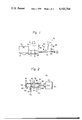
- FIGS. 2 and 3 are schematic sectional views of a downshift valve employed in the control system of the invention, which views respectively show first and second positions of the downshift valve;
- FIG. 4 is an illustration showing downshift and upshift characteristics of the automatic power transmission with the control system according to the present invention, the illustration being plotted of the throttle opening versus vehicle speed.
- an automatic power transmission control system 10 is shown as communicating with an internal combustion engine 12, an automatic power transmission proper 14 of known construction and a propeller shaft 16 drivingly connected to the transmission proper 14.
- the engine 12 has therein conventional means producing a throttle pressure the magnitude of which is substantially proportional to the output of the engine 12.
- the means communicates with a below-mentioned throttle valve (30) so as to produce the throttle pressure which is substantially proportional to the opening degree of the throttle valve.
- the automatic power transmission proper 14 includes therein a conventional downshift passage (not shown) into which a hydraulic fluid under variable pressure is introduced for continually changing the points at which the transmission shift to the next lower speed gear ratio.
- the control system 10 generally comprises a D.C. source 18, a kickdown switch 20 operated by an accelerator pedal 22, a downshift switch 24 operated by a brake pedal 26, and a downshift valve 28 connected to the transmission proper 14, the detailed construction of the downshift valve being shown in FIGS. 2 and 3.
- the kickdown switch 20 is disposed between the D.C. source 18 and the downshift valve 28 and closes for causing the energization of the downshift valve 28 when the accelerator pedal 22 is fully depressed to fully open the throttle valve 30.
- the downshift switch 24 is disposed between the D.C. source 18 and the downshift valve 28 through a diode 32 and closes when the brake pedal 26 is depressed.
- Indicated by the numeral 34 is brake lamp which lights up in response to the closing of the switch 24.
- the diode 32 is arranged to block current directed to the brake lamp 34 from the D.C. source 18 when the kickdown switch 20 closes and simultaneously, the downshift switch 24 is open. Thus, the closing of the kickdown switch 20 does not light up the brake lamp 34.
- FIGS. 2 and 3 The detailed construction of the downshift valve 28 is illustrated in FIGS. 2 and 3, in which two positions of the downshift valve are respectively shown.
- the downshift valve 28 comprises a valve body 36 formed with a chamber 38 including a first annular recess 40, a second annular recess 42, a third annular recess 44 and a fourth annular recess 46.
- the first and second annular recesses 40 and 42 respectively communicate with a throttle pressure passage 48 and a line pressure passage 50.
- the line pressure passage 50 is filled with a hydraulic fluid supplied from a conventional fluid supply (not shown).
- the third annular recess 44 is fluidly connected through a downshift passage 52 to the before-mentioned downshift passage having, for example, a 1-2 shift valve (not shown) and a 2-3 shift valve (not shown) which are operatively mounted on the transmission proper 14 in a conventional manner.
- the connection of the third annular recess 44 with the downshift passage is so arranged that when some hydraulic fluid under pressure is introduced into the downshift passage, downshift shifting points at which the transmission proper 14 shift down to the next lower speed gear ratio range are discontinuously moved toward the higher vehicle speed side and are finally settled down at predetermined positions of the higher vehicle speed side.
- the fourth anuular recess 46 communicates with a fluid reservoir tank (not shown) through a drain passage 54.
- valve spool 56 Axially slidably received in the chamber 38 of the valve body 36 is a valve spool 56 which has spaced first and second lands 58 and 60 with an identical diameter, and an annular groove formed between the lands 58 and 60.
- the valve spool 56 has first and second positions.
- the first position is a position in which as shown well in FIG. 2, the first land 58 blocks the fluid communication between the first and second annular recesses 40 and 42 and simultaneously the second land 60 blocks the fluid communication between the third and fourth annular recesses 44 and 46.
- the second and third annular recesses 42 and 44 fluidly communicate with each other.
- the second position is a position in which, as shown in FIG.
- the first land 58 blocks not only the fluid communication between the first and second annular recesses 40 and 42 but also the fluid communication between the second and third annular recesses 42 and 44 and simultaneously the second land 60 opens the fluid communication between the third and fourth annular recesses 44 and 46.
- the only purpose of feeding the throttle pressure into the first recess 40 is for it to act on the end surface of the land 58, not to communicate with any other recesses.
- a solenoid device 64 Adjacent the valve body 36 is located a solenoid device 64 which comprises a solenoid 66 with a coil having one end connected to both the above-mentioned kickdown switch 20 and the diode 32 and the other end grounded, and a plunger 68 which projects toward the second land 60 to move the valve spool 56 into the first position of FIG. 2 when the coil of the solenoid 66 is electrically energized.
- valve spool 56 remains in the first position when the coil of the solenoid 66 is energized and simultaneously the throttle pressure exceeds the predetermined level. This condition is induced as a result of closing the kickdown switch 20 in response to the full depression of the accelerator pedal 22.
- the driver wishes to accelerate the vehicle for passing a vehicle ahead at maximum speed, he depresses the accelerator pedal 22 to close the kickdown switch 20.
- the coil of the solenoid 66 is thus energized with a result that the downshifting of the transmission proper 14 is achieved in the same manner as described before.
- the transmission proper 14 provides the propeller shaft 16 with increased torque, so that the maximum acceleration of the vehicle is achieved.
- FIG. 4 shows upshift and downshift characteristics of the transmission proper 14 equipped with the control system of the present invention.
- First, second and third gear ratios of the transmission proper 14 are represented by the letters I, II and III.
- the solid lines represent respective shifting points in the case of the upshift, while the broken lines indicate the shifting points in the case of the downshift.
- the zone positioned above the line designated by KD is a zone in which the kickdown switch 20 closes causing the valve spool 56 of the downshift valve 28 to take the first position shown in FIG. 2. Within this zone, the shifting points take place at a higher vehicle speed.
- the other zone positioned below the line designated by DS is a zone in which the downshift switch 24 closes to allow the valve spool 56 to take the first position also. Also within this zone, the shifting points take place at the higher vehicle speed.
- the deceleration of the vehicle at a relatively high speed cruising can be made by the aid of engine braking by only temporary depression of the brake pedal 26.
- control system of the present invention can be constructed only by partially changing a part of a conventional one, it can be made in a relatively economical manner.
- control system of the subject invention has been shown to be applied to the three-forward-speed automatic power transmission, it is also possible to use the subject control system to other type automatic power transmissions, such as two-forward-speed and four-forward-speed transmissions.
Landscapes
- Engineering & Computer Science (AREA)
- General Engineering & Computer Science (AREA)
- Mechanical Engineering (AREA)
- Control Of Transmission Device (AREA)
Applications Claiming Priority (2)
| Application Number | Priority Date | Filing Date | Title |
|---|---|---|---|
| JP50135024A JPS5259265A (en) | 1975-11-12 | 1975-11-12 | Automatic transmission with downshift maintaining mechanism |
| JP50-135024 | 1975-11-12 |
Publications (1)
| Publication Number | Publication Date |
|---|---|
| US4103764A true US4103764A (en) | 1978-08-01 |
Family
ID=15142139
Family Applications (1)
| Application Number | Title | Priority Date | Filing Date |
|---|---|---|---|
| US05/740,712 Expired - Lifetime US4103764A (en) | 1975-11-12 | 1976-11-10 | Control system for an automatic power transmission |
Country Status (3)
| Country | Link |
|---|---|
| US (1) | US4103764A (enExample) |
| JP (1) | JPS5259265A (enExample) |
| GB (1) | GB1529480A (enExample) |
Cited By (13)
| Publication number | Priority date | Publication date | Assignee | Title |
|---|---|---|---|---|
| US4181204A (en) * | 1977-06-16 | 1980-01-01 | Toyota Jidosha Kogyo Kabushiki Kaisha | Oil pressure control means for an automatic transmission |
| FR2447288A1 (fr) * | 1979-01-29 | 1980-08-22 | Gen Motors Corp | Dispositif de commande d'un embrayage de convertisseur de couple pour vehicule |
| FR2448076A1 (fr) * | 1979-02-02 | 1980-08-29 | Nissan Motor | Systeme de transmission automatique pourvu d'une fonction de frein moteur |
| US4365526A (en) * | 1979-05-21 | 1982-12-28 | Nissan Motor Co., Ltd. | Apparatus for controlling line pressure of automatic transmission |
| US4466519A (en) * | 1980-04-30 | 1984-08-21 | International Harvester Co. | Drive and brake system for motor vehicles with four-wheel drive |
| US4614258A (en) * | 1983-07-27 | 1986-09-30 | Kabushiki Kaisha Daikin Seisakusho | Automatic speed change control methods for self-movable vehicle |
| US4765202A (en) * | 1985-07-30 | 1988-08-23 | Nissan Motor Co., Ltd. | Engine brake control for automatic transmission |
| US4770066A (en) * | 1985-07-15 | 1988-09-13 | Nissan Motor Co., Ltd. | Engine brake control in automatic transmission |
| US5069085A (en) * | 1990-02-15 | 1991-12-03 | Jatco Corporation | Shift control system for automatic power transmission with enhanced shifting transition characteristics |
| US6269295B1 (en) | 1999-11-30 | 2001-07-31 | Caterpillar Inc. | Method and apparatus for transmission control during braking |
| US6620077B2 (en) | 2001-09-04 | 2003-09-16 | Caterpillar Inc | Work machine having a drive train with an enhanced braking mode |
| US20080129109A1 (en) * | 2006-12-01 | 2008-06-05 | Clark Equipment Company | Shift assisted braking for a power machine or vehicle |
| CN103003598A (zh) * | 2010-06-10 | 2013-03-27 | 沃易斯专利有限公司 | 用于在一个变速器上设置传动比转换或提高电动马达扭矩的方法 |
Families Citing this family (3)
| Publication number | Priority date | Publication date | Assignee | Title |
|---|---|---|---|---|
| DE3139985A1 (de) * | 1981-07-15 | 1983-02-03 | Bosch Gmbh Robert | Verfahren zum steuern von automatischen getrieben in kraftfahrzeugen |
| US5048650A (en) * | 1988-07-19 | 1991-09-17 | Nissan Motor Co., Ltd. | Engine brake running control for automatic transmission in automatic drive range |
| GB2235513A (en) * | 1989-06-07 | 1991-03-06 | Electro Hydraulic Technology L | Clutch control valve |
Citations (9)
| Publication number | Priority date | Publication date | Assignee | Title |
|---|---|---|---|---|
| US2872000A (en) * | 1953-05-13 | 1959-02-03 | Gen Motors Corp | Transmission and brake control system |
| US3001415A (en) * | 1954-05-11 | 1961-09-26 | Borg Warner | Transmission |
| US3523597A (en) * | 1969-03-13 | 1970-08-11 | Ford Motor Co | Automatic power transmission control system whereby application of vehicle brakes downshifts the transmission |
| US3667579A (en) * | 1970-11-18 | 1972-06-06 | Joseph Vizza | Brake operated transmission shifter |
| US3733930A (en) * | 1970-04-19 | 1973-05-22 | Nissan Motor | Electronic control device for automatic power transmission |
| US3752275A (en) * | 1972-02-09 | 1973-08-14 | O Mueller | Transmission with brake operated down shifter |
| US3859873A (en) * | 1972-08-24 | 1975-01-14 | Nissan Motor | Line pressure modulating device for an automatic power transmission |
| US3974720A (en) * | 1974-04-25 | 1976-08-17 | Nissan Motor Co., Ltd. | Downshift control circuit for hydraulic transmission |
| US4008630A (en) * | 1973-09-18 | 1977-02-22 | Aisin Seiki Kabushiki Kaisha | Fluid pressure control system for automatic transmissions |
-
1975
- 1975-11-12 JP JP50135024A patent/JPS5259265A/ja active Granted
-
1976
- 1976-11-10 US US05/740,712 patent/US4103764A/en not_active Expired - Lifetime
- 1976-11-12 GB GB47284/76A patent/GB1529480A/en not_active Expired
Patent Citations (9)
| Publication number | Priority date | Publication date | Assignee | Title |
|---|---|---|---|---|
| US2872000A (en) * | 1953-05-13 | 1959-02-03 | Gen Motors Corp | Transmission and brake control system |
| US3001415A (en) * | 1954-05-11 | 1961-09-26 | Borg Warner | Transmission |
| US3523597A (en) * | 1969-03-13 | 1970-08-11 | Ford Motor Co | Automatic power transmission control system whereby application of vehicle brakes downshifts the transmission |
| US3733930A (en) * | 1970-04-19 | 1973-05-22 | Nissan Motor | Electronic control device for automatic power transmission |
| US3667579A (en) * | 1970-11-18 | 1972-06-06 | Joseph Vizza | Brake operated transmission shifter |
| US3752275A (en) * | 1972-02-09 | 1973-08-14 | O Mueller | Transmission with brake operated down shifter |
| US3859873A (en) * | 1972-08-24 | 1975-01-14 | Nissan Motor | Line pressure modulating device for an automatic power transmission |
| US4008630A (en) * | 1973-09-18 | 1977-02-22 | Aisin Seiki Kabushiki Kaisha | Fluid pressure control system for automatic transmissions |
| US3974720A (en) * | 1974-04-25 | 1976-08-17 | Nissan Motor Co., Ltd. | Downshift control circuit for hydraulic transmission |
Cited By (16)
| Publication number | Priority date | Publication date | Assignee | Title |
|---|---|---|---|---|
| US4181204A (en) * | 1977-06-16 | 1980-01-01 | Toyota Jidosha Kogyo Kabushiki Kaisha | Oil pressure control means for an automatic transmission |
| FR2447288A1 (fr) * | 1979-01-29 | 1980-08-22 | Gen Motors Corp | Dispositif de commande d'un embrayage de convertisseur de couple pour vehicule |
| US4257503A (en) * | 1979-01-29 | 1981-03-24 | General Motors Corporation | Disengagement control for a torque converter clutch |
| FR2448076A1 (fr) * | 1979-02-02 | 1980-08-29 | Nissan Motor | Systeme de transmission automatique pourvu d'une fonction de frein moteur |
| US4350234A (en) * | 1979-02-02 | 1982-09-21 | Nissan Motor Co., Ltd. | Automatic transmission system provided with a function of engine brake |
| US4365526A (en) * | 1979-05-21 | 1982-12-28 | Nissan Motor Co., Ltd. | Apparatus for controlling line pressure of automatic transmission |
| US4466519A (en) * | 1980-04-30 | 1984-08-21 | International Harvester Co. | Drive and brake system for motor vehicles with four-wheel drive |
| US4614258A (en) * | 1983-07-27 | 1986-09-30 | Kabushiki Kaisha Daikin Seisakusho | Automatic speed change control methods for self-movable vehicle |
| US4770066A (en) * | 1985-07-15 | 1988-09-13 | Nissan Motor Co., Ltd. | Engine brake control in automatic transmission |
| US4765202A (en) * | 1985-07-30 | 1988-08-23 | Nissan Motor Co., Ltd. | Engine brake control for automatic transmission |
| US5069085A (en) * | 1990-02-15 | 1991-12-03 | Jatco Corporation | Shift control system for automatic power transmission with enhanced shifting transition characteristics |
| US6269295B1 (en) | 1999-11-30 | 2001-07-31 | Caterpillar Inc. | Method and apparatus for transmission control during braking |
| US6620077B2 (en) | 2001-09-04 | 2003-09-16 | Caterpillar Inc | Work machine having a drive train with an enhanced braking mode |
| US20080129109A1 (en) * | 2006-12-01 | 2008-06-05 | Clark Equipment Company | Shift assisted braking for a power machine or vehicle |
| US7762923B2 (en) | 2006-12-01 | 2010-07-27 | Clark Equipment Company | Shift assisted braking for a power machine or vehicle |
| CN103003598A (zh) * | 2010-06-10 | 2013-03-27 | 沃易斯专利有限公司 | 用于在一个变速器上设置传动比转换或提高电动马达扭矩的方法 |
Also Published As
| Publication number | Publication date |
|---|---|
| JPS562627B2 (enExample) | 1981-01-21 |
| JPS5259265A (en) | 1977-05-16 |
| GB1529480A (en) | 1978-10-18 |
Similar Documents
| Publication | Publication Date | Title |
|---|---|---|
| US4103764A (en) | Control system for an automatic power transmission | |
| US4350234A (en) | Automatic transmission system provided with a function of engine brake | |
| EP0045962B1 (en) | Control system for automatic transmission for automotive vehicle | |
| EP0049476B1 (en) | Lock-up control method of and system for automatic transmission for automotive vehicle having engine provided with fuel cut means | |
| US4457410A (en) | Lock-up control system for a lock-up type automatic transmission of an automotive vehicle having an engine | |
| EP0044461B1 (en) | Lock-up control system for lock-up type automatic transmission | |
| EP0041238B1 (en) | Control system for engine of automotive vehicle equipped with lock-up type automatic transmission | |
| US3709068A (en) | Power transmission | |
| JPS6246055A (ja) | 車両用自動変速機 | |
| US4563917A (en) | Two stage kickdown control system for a motor vehicle automatic transmission | |
| US4020718A (en) | Hydraulic system for an automatic power transmission | |
| JPS58137650A (ja) | 自動変速機の変速制御装置 | |
| JPS6346303B2 (enExample) | ||
| US4395926A (en) | Hydraulic control system for automatic transmission | |
| US4134312A (en) | Control system for an automatic power transmission | |
| JPS6318055B2 (enExample) | ||
| JPS5948899B2 (ja) | 自動変速機のシフトバルブ | |
| JPS6444338A (en) | Method of controlling clutch in continuously variable transmission | |
| JPS6314223B2 (enExample) | ||
| EP0047670A2 (en) | Control system for automatic transmission with overdrive device | |
| JPS59183159A (ja) | 車両用自動変速機の制御装置 | |
| CA2071404A1 (en) | Electro-hydraulic shift interlock apparatus for an automatic transmission | |
| JPS59183158A (ja) | 車両用自動変速機の制御装置 | |
| JPS61103044A (ja) | 自動変速機 | |
| JPH0520622B2 (enExample) |