US4084998A - Device for gripping, pressing and depositing tire cores - Google Patents
Device for gripping, pressing and depositing tire cores Download PDFInfo
- Publication number
- US4084998A US4084998A US05/676,987 US67698776A US4084998A US 4084998 A US4084998 A US 4084998A US 67698776 A US67698776 A US 67698776A US 4084998 A US4084998 A US 4084998A
- Authority
- US
- United States
- Prior art keywords
- rings
- ring
- gripping
- recited
- mentioned
- Prior art date
- Legal status (The legal status is an assumption and is not a legal conclusion. Google has not performed a legal analysis and makes no representation as to the accuracy of the status listed.)
- Expired - Lifetime
Links
- 238000000151 deposition Methods 0.000 title claims abstract description 5
- 238000003825 pressing Methods 0.000 title claims abstract description 5
- 238000007493 shaping process Methods 0.000 claims description 5
- 239000011324 bead Substances 0.000 claims 2
- 239000012530 fluid Substances 0.000 claims 2
- 239000000463 material Substances 0.000 abstract description 4
- 238000000034 method Methods 0.000 description 6
- 238000010276 construction Methods 0.000 description 2
- 230000003292 diminished effect Effects 0.000 description 2
- 239000011796 hollow space material Substances 0.000 description 2
- 238000004519 manufacturing process Methods 0.000 description 2
- 230000006978 adaptation Effects 0.000 description 1
- 230000001627 detrimental effect Effects 0.000 description 1
- 230000000694 effects Effects 0.000 description 1
- 238000004073 vulcanization Methods 0.000 description 1
- 238000004804 winding Methods 0.000 description 1
Images

Classifications
-
- B—PERFORMING OPERATIONS; TRANSPORTING
- B29—WORKING OF PLASTICS; WORKING OF SUBSTANCES IN A PLASTIC STATE IN GENERAL
- B29D—PRODUCING PARTICULAR ARTICLES FROM PLASTICS OR FROM SUBSTANCES IN A PLASTIC STATE
- B29D30/00—Producing pneumatic or solid tyres or parts thereof
- B29D30/06—Pneumatic tyres or parts thereof (e.g. produced by casting, moulding, compression moulding, injection moulding, centrifugal casting)
- B29D30/08—Building tyres
- B29D30/20—Building tyres by the flat-tyre method, i.e. building on cylindrical drums
- B29D30/32—Fitting the bead-rings or bead-cores; Folding the textile layers around the rings or cores
- B29D2030/3207—Positioning the beads
Definitions
- This invention relates to a device for gripping, pressing and depositing a tire core upon a raw tire blank.
- An object of the present invention is the making of a device of the described type which produces a tire blank the core of which lies with the highest precision upon the provided location and, furthermore, which can not have a deviation in the lateral direction.
- the device of the present invention is primarily used in connection with constructions wherein the tire core can be additionally placed under tension at the tire blank at the radial inner side.
- a supporting cylinder which is shiftable axially and which consists of two rings located side by side and having parallel annular troughs upon their inner side.
- the annular troughs are airtightly covered by separate rings consisting of polyesterurethane or similar tough elastic plastic material with a high E-modulus.
- These rings have crack zones located mirror-like symmetrically in several radial planes; they are rigid against change in shape and cross-sectionally they are adjustable as toggle joints relatively to each other.
- the ring zones located closest to the ring center are swingable inwardly tongs-like in radial planes by increased air pressure.
- the axial shifting capacity of the supporting cylinder makes it possible to grip the tire core upon a centering drum, to press it while adjusting in axial direction and then place it precisely upon the location provided in the tire blank. All procedures can be carried out with great precision and with simple means. The result is a tire blank the tire core of which extends precisely radially and axially and which lies precisely upon the provided location.
- the plastic ring consists preferably of three ring sections which are cross-sectionally movable toggle-like to each other.
- the part lying at the center of the supporting cylinder serves as the gripping ring, while the two other parts serve as steering rings for the gripping ring.
- the crack zones provided for the plastic ring lie relatively to the center of the cylinder behind each other radially outwardly, outwardly, innerly, outwardly. The provision of these crack zones makes possible due to the great hardness and elasticity of the material a shape change by each pressure which leads precisely to the provided movement procedures in space.
- edges of the plastic rings have strengthened ring feet and are clamped airtightly between correspondingly shaped form disks. This makes possible a simple and yet precise fixing of the ring edges.
- the fixing arrangement takes into consideration the provided changes in shape of the ring sections.
- the inner edges of the ring form parts are advantageously provided with limiting stops. These stops provide primarily moving procedures which can be very precisely carried out. They prevent the particularly wide ring section from curving due to air pressure and eventually from changing the shape of the toggle joint beyond the dead center. Such a curvature could cause the ring section lying on the core wire to be applied with diminished force. Furthermore, it is advantageous to provide exchangeable distancing disks between the mold rings. These disks make possible the setting of the device to tire wires of different thicknesses. In order to make possible the shaping procedure of the plastic rings with diminished air pressure and also with pressed air, their section free of pressure is located in the middle shaping range between two extreme positions. This makes it possible to carry out the operation and the forming procedures with simple means and moderate operational pressures. Under special conditions the setting can be also carried out in such manner that only one plastic ring operates against a fixed radially directed disk.
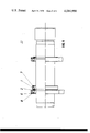
- FIGS. 1, 2 and 3 are similar sectional views of a part of the device illustrating different operational positions.
- FIG. 4 is a side view partly in section illustrating the arrangement of gripping devices upon a winding drum.
- the device illustrated in FIGS. 1, 2 and 3 comprises a supporting cylinder consisting of two mold rings land 2. Fixing disks 3, 4, 5 and 6 are provided at the front sides of these rings. These disks in combination with the rings make is possible to fix the edges of the two plastic rings 7 and 8 in corresponding recesses.
- a distancing disk 9 which in set to the axial size of the tire core 10, is located between the fixing rings 4 and 5.
- the plastic rings consists of polyesterurethane with an E-modulus of approximately 500 Kp/mm 2 .
- the plastic rings 7 and 8 are mirror-like symmetrical relatively to each other. They have four crack zones 11, 12, 13 and 14. When pressed air reaches the trough shaped hollow space 16 through the opening 15, there is a change in shape of these crack zones, whereby the inwardly bent parts 17 and 18 are stretched toggle-like, and the part 19 swings. This condition is illustrated on the left side of FIG. 2.
- the ring portion 19 is moved upon the tire core 10, the hollow space 20 is also subjected to air pressure, so that this plastic ring carries out mirror-like the same movement.
- the core 10 is pressed between the ring portions 19 and 21 and directed at the same time.
- the centering drum 23 upon which lies the core 10 cooperates from the radial inwardly located side. In this condition the core including the gripping device can be shifted axially and thereupon placed upon the tire blank.
- the crack zone 13 is somewhat shifted in the direction toward the central section of the ring portion 19. This makes possible a strong pressure between the ring portion and the wire core.
- the crack zones are so arranged that they are closed at the steering rings in the stretched condition. This makes it possible to provide a particularly high pressure in combination with the toggle effect, which is also of importance for the property of the tire core. This substantially eliminates a later form change of the tire core when tissues are wrapped.
- FIGS. 1, 2 and 3 are on the scale 1:2 to the actual size. This makes it possible to easily determine the thickness of the plastic rings, the depth of notching in the crack zones and the length relationship of the individual toggle levers to each other.
- FIG. 4 shows two gripping devices placed in the provided position after the removal of a separate core wire from the centering drum 22.
- the two gripping devices differ from each other in that one of them is them is already described and illustrated in FIGS. 1-3 as having two rings 1 and 2.
- the second illustrated gripping device has only one ring and presses the core wire against a fixed stop ring. The drawing clearly shows this construction.
Landscapes
- Engineering & Computer Science (AREA)
- Mechanical Engineering (AREA)
- Tyre Moulding (AREA)
- Heating, Cooling, Or Curing Plastics Or The Like In General (AREA)
- Tires In General (AREA)
Applications Claiming Priority (2)
| Application Number | Priority Date | Filing Date | Title |
|---|---|---|---|
| DT2525038 | 1975-06-05 | ||
| DE2525038A DE2525038C3 (de) | 1975-06-05 | 1975-06-05 | Vorrichtung zum Greifen, Pressen und Absetzen von Wulstkernen |
Publications (1)
| Publication Number | Publication Date |
|---|---|
| US4084998A true US4084998A (en) | 1978-04-18 |
Family
ID=5948350
Family Applications (1)
| Application Number | Title | Priority Date | Filing Date |
|---|---|---|---|
| US05/676,987 Expired - Lifetime US4084998A (en) | 1975-06-05 | 1976-04-14 | Device for gripping, pressing and depositing tire cores |
Country Status (11)
| Country | Link |
|---|---|
| US (1) | US4084998A (enExample) |
| JP (1) | JPS51148775A (enExample) |
| AT (1) | AT344526B (enExample) |
| CS (1) | CS188139B2 (enExample) |
| DD (1) | DD124370A5 (enExample) |
| DE (1) | DE2525038C3 (enExample) |
| FR (1) | FR2313201A1 (enExample) |
| GB (1) | GB1516592A (enExample) |
| IT (1) | IT1059036B (enExample) |
| NL (1) | NL7605031A (enExample) |
| SU (1) | SU674659A3 (enExample) |
Cited By (1)
| Publication number | Priority date | Publication date | Assignee | Title |
|---|---|---|---|---|
| US20050067088A1 (en) * | 2001-12-27 | 2005-03-31 | Bosio Gian Luigi | Process and apparatus for building a tyre |
Citations (6)
| Publication number | Priority date | Publication date | Assignee | Title |
|---|---|---|---|---|
| US3078204A (en) * | 1959-08-25 | 1963-02-19 | Goodyear Tire & Rubber | Method of and apparatus for building tires |
| US3121653A (en) * | 1960-08-16 | 1964-02-18 | Dunlop Rubber Co | Type building machines |
| US3224921A (en) * | 1962-05-24 | 1965-12-21 | Nat Standard Co | Bead placing and sealing apparatus for tire building machine |
| US3598673A (en) * | 1966-12-30 | 1971-08-10 | Pirelli | Method for building up pneumatic tires |
| US3721600A (en) * | 1970-08-19 | 1973-03-20 | Nrm Corp | Tire building machine |
| US3944456A (en) * | 1974-05-06 | 1976-03-16 | Nrm Corporation | Tire building machine |
-
1975
- 1975-06-05 DE DE2525038A patent/DE2525038C3/de not_active Expired
-
1976
- 1976-04-14 US US05/676,987 patent/US4084998A/en not_active Expired - Lifetime
- 1976-04-15 FR FR7611146A patent/FR2313201A1/fr active Granted
- 1976-04-29 IT IT22830/76A patent/IT1059036B/it active
- 1976-05-07 GB GB18946/76A patent/GB1516592A/en not_active Expired
- 1976-05-11 NL NL7605031A patent/NL7605031A/xx not_active Application Discontinuation
- 1976-05-18 CS CS763303A patent/CS188139B2/cs unknown
- 1976-05-19 JP JP51057708A patent/JPS51148775A/ja active Granted
- 1976-05-21 AT AT373976A patent/AT344526B/de not_active IP Right Cessation
- 1976-06-02 DD DD193141A patent/DD124370A5/xx unknown
- 1976-06-04 SU SU762366652A patent/SU674659A3/ru active
Patent Citations (6)
| Publication number | Priority date | Publication date | Assignee | Title |
|---|---|---|---|---|
| US3078204A (en) * | 1959-08-25 | 1963-02-19 | Goodyear Tire & Rubber | Method of and apparatus for building tires |
| US3121653A (en) * | 1960-08-16 | 1964-02-18 | Dunlop Rubber Co | Type building machines |
| US3224921A (en) * | 1962-05-24 | 1965-12-21 | Nat Standard Co | Bead placing and sealing apparatus for tire building machine |
| US3598673A (en) * | 1966-12-30 | 1971-08-10 | Pirelli | Method for building up pneumatic tires |
| US3721600A (en) * | 1970-08-19 | 1973-03-20 | Nrm Corp | Tire building machine |
| US3944456A (en) * | 1974-05-06 | 1976-03-16 | Nrm Corporation | Tire building machine |
Cited By (2)
| Publication number | Priority date | Publication date | Assignee | Title |
|---|---|---|---|---|
| US20050067088A1 (en) * | 2001-12-27 | 2005-03-31 | Bosio Gian Luigi | Process and apparatus for building a tyre |
| US7476286B2 (en) * | 2001-12-27 | 2009-01-13 | Pirelli Pneumatici S.P.A. | Method of manufacturing a tyre and apparatus for building a tyre |
Also Published As
| Publication number | Publication date |
|---|---|
| NL7605031A (nl) | 1976-12-07 |
| SU674659A3 (ru) | 1979-07-15 |
| JPS51148775A (en) | 1976-12-21 |
| CS188139B2 (en) | 1979-02-28 |
| JPS5646983B2 (enExample) | 1981-11-06 |
| FR2313201B1 (enExample) | 1978-05-05 |
| DE2525038C3 (de) | 1978-04-27 |
| DD124370A5 (enExample) | 1977-02-16 |
| FR2313201A1 (fr) | 1976-12-31 |
| GB1516592A (en) | 1978-07-05 |
| IT1059036B (it) | 1982-05-31 |
| ATA373976A (de) | 1977-11-15 |
| DE2525038B2 (de) | 1977-09-15 |
| DE2525038A1 (de) | 1976-12-16 |
| AT344526B (de) | 1978-07-25 |
Similar Documents
| Publication | Publication Date | Title |
|---|---|---|
| US2300760A (en) | Molding of articles by reinforced synthetic resins | |
| KR870009829A (ko) | 고무타이어의 성형 및 경화용 금형 | |
| JPH01157838A (ja) | 成型ドラム | |
| ATE278524T1 (de) | Formwerkzeug zum formen einer reifenlauffläche | |
| DE2659587B2 (de) | Form für einen Formheizbalg zur Luftreifenherstellung | |
| CA1082865A (en) | Machine for performing in one single operating cycle the molding and curing of a tread ring for pneumatic tires | |
| MXPA00001947A (es) | Seccion de molde y costillas de matriz para molde de curado de neumatico. | |
| US4084998A (en) | Device for gripping, pressing and depositing tire cores | |
| US2333588A (en) | Molding apparatus | |
| US2839864A (en) | Handles for implements | |
| JPH0116661B2 (enExample) | ||
| US3917791A (en) | Method for the bellowless vulcanization of tire blanks | |
| US3948591A (en) | Apparatus for the bellowless vulcanization of tire blanks | |
| GB1378219A (en) | Method and apparatus for producing pneumatic vehicles tyres | |
| JPH0259052B2 (enExample) | ||
| US3169522A (en) | Spring rimmed diaphragm and method of producing the same | |
| JPS595377B2 (ja) | 自動車用ホイルの製造方法 | |
| US2514964A (en) | Method and equipment for track manufacture | |
| DE112009002265T5 (de) | Verfahren und Vorrichtung für die Herstellung eines Wulstes | |
| US4181483A (en) | Apparatus for the bellowless vulcanization of tire blanks | |
| US2880459A (en) | Tire shaping and curing presses | |
| US4079980A (en) | Device for transporting annular running strips for pneumatic tires | |
| SU905111A1 (ru) | Пресс-форма дл изготовлени полых полимерных изделий | |
| US3292311A (en) | Abrasive wheels | |
| US2598158A (en) | Apparatus for making v belts |