US4083516A - Reel mounting for recording or reproducing apparatus - Google Patents
Reel mounting for recording or reproducing apparatus Download PDFInfo
- Publication number
- US4083516A US4083516A US05/752,817 US75281776A US4083516A US 4083516 A US4083516 A US 4083516A US 75281776 A US75281776 A US 75281776A US 4083516 A US4083516 A US 4083516A
- Authority
- US
- United States
- Prior art keywords
- mandrel
- reels
- shaft
- reel
- support
- Prior art date
- Legal status (The legal status is an assumption and is not a legal conclusion. Google has not performed a legal analysis and makes no representation as to the accuracy of the status listed.)
- Expired - Lifetime
Links
- 230000000903 blocking effect Effects 0.000 claims abstract 3
- 238000006073 displacement reaction Methods 0.000 claims description 6
- 230000008878 coupling Effects 0.000 claims description 3
- 238000010168 coupling process Methods 0.000 claims description 3
- 238000005859 coupling reaction Methods 0.000 claims description 3
- 230000000881 depressing effect Effects 0.000 claims 1
- 210000002105 tongue Anatomy 0.000 description 31
- 238000003780 insertion Methods 0.000 description 3
- 230000037431 insertion Effects 0.000 description 3
- 230000033001 locomotion Effects 0.000 description 3
- 230000002093 peripheral effect Effects 0.000 description 3
- 230000005540 biological transmission Effects 0.000 description 2
- 230000000994 depressogenic effect Effects 0.000 description 2
- 230000004048 modification Effects 0.000 description 2
- 238000012986 modification Methods 0.000 description 2
- 238000000926 separation method Methods 0.000 description 2
- 238000006243 chemical reaction Methods 0.000 description 1
- 210000000078 claw Anatomy 0.000 description 1
- 230000009977 dual effect Effects 0.000 description 1
- 238000003384 imaging method Methods 0.000 description 1
- 238000004519 manufacturing process Methods 0.000 description 1
- 239000000463 material Substances 0.000 description 1
- 230000007246 mechanism Effects 0.000 description 1
- 239000002184 metal Substances 0.000 description 1
- 230000000284 resting effect Effects 0.000 description 1
- 230000002269 spontaneous effect Effects 0.000 description 1
- 229920003002 synthetic resin Polymers 0.000 description 1
- 239000000057 synthetic resin Substances 0.000 description 1
- 230000007723 transport mechanism Effects 0.000 description 1
Images


Classifications
-
- B—PERFORMING OPERATIONS; TRANSPORTING
- B65—CONVEYING; PACKING; STORING; HANDLING THIN OR FILAMENTARY MATERIAL
- B65H—HANDLING THIN OR FILAMENTARY MATERIAL, e.g. SHEETS, WEBS, CABLES
- B65H16/00—Unwinding, paying-out webs
- B65H16/02—Supporting web roll
- B65H16/04—Supporting web roll cantilever type
-
- G—PHYSICS
- G03—PHOTOGRAPHY; CINEMATOGRAPHY; ANALOGOUS TECHNIQUES USING WAVES OTHER THAN OPTICAL WAVES; ELECTROGRAPHY; HOLOGRAPHY
- G03B—APPARATUS OR ARRANGEMENTS FOR TAKING PHOTOGRAPHS OR FOR PROJECTING OR VIEWING THEM; APPARATUS OR ARRANGEMENTS EMPLOYING ANALOGOUS TECHNIQUES USING WAVES OTHER THAN OPTICAL WAVES; ACCESSORIES THEREFOR
- G03B21/00—Projectors or projection-type viewers; Accessories therefor
- G03B21/14—Details
- G03B21/32—Details specially adapted for motion-picture projection
- G03B21/321—Holders for films, e.g. reels, cassettes, spindles
-
- G—PHYSICS
- G11—INFORMATION STORAGE
- G11B—INFORMATION STORAGE BASED ON RELATIVE MOVEMENT BETWEEN RECORD CARRIER AND TRANSDUCER
- G11B15/00—Driving, starting or stopping record carriers of filamentary or web form; Driving both such record carriers and heads; Guiding such record carriers or containers therefor; Control thereof; Control of operating function
- G11B15/60—Guiding record carrier
- G11B15/66—Threading; Loading; Automatic self-loading
- G11B15/662—Positioning or locking of spool or reel
-
- B—PERFORMING OPERATIONS; TRANSPORTING
- B65—CONVEYING; PACKING; STORING; HANDLING THIN OR FILAMENTARY MATERIAL
- B65H—HANDLING THIN OR FILAMENTARY MATERIAL, e.g. SHEETS, WEBS, CABLES
- B65H2301/00—Handling processes for sheets or webs
- B65H2301/40—Type of handling process
- B65H2301/41—Winding, unwinding
- B65H2301/413—Supporting web roll
- B65H2301/4134—Both ends type arrangement
- B65H2301/41342—Both ends type arrangement shaft transversing the roll
- B65H2301/41344—Both ends type arrangement shaft transversing the roll the roll being fixed to the shaft (e.g. by clamping)
Definitions
- Our present invention relates to a mounting for a pair of reels, specifically a supply reel and a take-up reel, in a recording or reproducing apparatus, such as a motion-picture camera, a movie projector or a tape recorder, handling an elongate recording medium.
- a recording or reproducing apparatus such as a motion-picture camera, a movie projector or a tape recorder, handling an elongate recording medium.
- the general object of our present invention is to provide an improved dual reel mounting for the purpose set forth including means for positively maintaining an axial separation between two reels carried on respective mandrels of substantially the same diameter.
- a more particular object of our invention is to provide reel-separating means becoming effective only after one reel has been fitted into the inner mandrel, so as not to interfere with the emplacement of that reel.
- a mounting of the general type referred to above includes retractable detent means carried by the mandrel-supporting shaft in the vicinity of a gap separating a first or outer mandrel from a second or inner mandrel of substantially the same diameter coaxially adjoining same, the detent means enabling emplacement of one reel on the second mandrel when in a radially withdrawn position and forming a stop for the other reel on the first mandrel when in a radially extended position.
- the user may operate a special actuating element after emplacement of one reel on the second mandrel; this actuating element could be an extremity of a lever arm forming a part of the detent means and lying generally axially in the withdrawn position, for example, or a rotatable knob on a member cammingly coacting with such an arm.
- the detent means may comprise one or more flexible tongues, integral with the first mandrel, each carrying a boss biased into its extended position in the path of the reel hub preferably by the inherent resiliency of the tongue.
- the tongues yield inwardly into a clearance of the body of the mandrel to give passage to a reel sliding thereover.
- inward flexing of the tongues is blocked by a relative axial shift between the first mandrel and an abutment receivable in its clearance.
- Such a shift, of either the abutment or the first mandrel itself may be brought about by a separate manual operation or automatically as a result of a thrust exerted by the already emplaced reel upon an axially shiftable end stop therefor.
- the end stop is preferably carried on the axially fixed second mandrel and may be provided with indexing means such as a resilient latch yieldably retaining it in a repressed position against a spring force urging the end stop toward the first mandrel.
- indexing means such as a resilient latch yieldably retaining it in a repressed position against a spring force urging the end stop toward the first mandrel.
- an abutment member integrally or otherwise linked with the end stop may normally depress the detent-forming bosses into their withdrawn position from which they are released upon a repression of the end stop by a reel fitted onto the second mandrel.
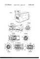
- FIG. 1 is a perspective view of a motion-picture projector equipped with a reel mounted according to our invention
- FIG. 2A is a side view, partly in section, of the reel mounting of FIG. 1 drawn to a larger scale, in conformity with one embodiment
- FIG. 2B is a cross-sectional view taken on the line IIB -- IIB of FIG. 2A;
- FIG. 3A is a view similar to FIG. 2A, showing another embodiment of our invention.
- FIG. 3B is a cross-sectional view taken on the line IIIB -- IIIB of FIG. 3A;
- FIG. 4A is another view similar to FIG. 2A, illustrating a further embodiment
- FIG. 4B is a longitudinal sectional view taken on the line IVB -- IVB of FIG. 4A;
- FIG. 4C is a cross-sectional view taken on the line IVC -- IVC of FIG. 4B;
- FIGS. 5 - 9 are still other views similar to FIG. 2A, illustrating yet further embodiments
- FIGS. 10A, 10B and 10C are fragmentary longitudinal sectional views of yet another embodiment as seen in respective directions XA -- XA, XB -- XB and XC -- XC of FIG. 10D, the latter representing a perspective view of a stop member included in this embodiment;
- FIGS. 11A and 11B are fragmentary side views, partly in section, of an additional embodiment shown in two different positions.
- FIG. 1 we have shown an essentially conventional motion-picture projector 1 provided with a transluminating screen 2 and with the usual objective and light source, not shown, for imaging a film on that screen.
- the film advanced by a nonillustrated transport mechanism such as a reciprocating traction claw, is continuously unwound from a supply reel and wound upon a take-up reel, the two reels (not shown in FIG. 1) being respectively carried on a pair of coaxial mandrels 4, 5 of like diameter held in a cantilevered position on a hollow supporting arm 3.
- a collar 6 on mandrel 5 see also FIG.
- arm 3 forms an axially fixed end stop for one of the reels, here specifically the take-up reel, it being assumed that arm 3 contains a transmission band for driving the mandrel 5 from a nonillustrated motor (which may be the same as that used for the film transport) by way of a friction clutch.
- FIG. 2A we have shown details of the mounting of mandrels 4 and 5 on supporting arm 3.
- a horizontal shaft 86 terminating in a head 86a, carries the first mandrel 4 and is freely rotatable therewith within the second mandrel 5 whose right-hand end, not shown, is rotatably journaled within arm 3.
- Shaft 86, supported only by mandrel 5, may thus be regarded as cantilevered on arm 3.
- Mandrel 5 is peripherally slitted to form several axially extending tongues 53 with bosses or lugs 53a which yield inwardly when a take-up reel 100 (FIGS. 10A, 10C and 10B) is axially fitted onto this mandrel by way of the adjoining mandrel 4, the bosses 53a serving to hold the reel in position on mandrel 5 during operation when the reel is rotatingly entrained by the mandrel via a key 70.
- mandrel 4 is provided with a pair of detent arms 7', 7" which are part of a pair of bell-crank levers also having transverse arms 8' and 8", the latter being in the shape of yokes pivoted to shaft 86 by a pair of pins 9 and 10 as best seen in FIG. 2B.
- detent arms 7' and 7" In the withdrawn position of detent arms 7' and 7" shown in full lines, these arms rest horizontally and therefore parallel to the mandrel axis against head 86a in diametrically opposite slots provided for this purpose in mandrel 4: the slots are shown to extend axially from the free end of the mandrel.
- arms 7' and 7" can be manually gripped for swinging the arms into an extended position, illustrated in phantom lines, in which they project radially from their slots and form a stop for a supply reel 15 (see FIG. 3A) subsequently fitted onto mandrel 4.
- a supply reel 15 see FIG. 3A
- the two reels are kept axially spaced apart so as not to interfere with each other's motion.
- FIGS. 3A and 3B the body of mandrel 4 is mounted with a friction fit on a shaft 87 again idling within mandrel 5.
- a milled knob 12 is rotatably carried on the free end of shaft 87 and is integral with a pair of flexible rods 13' and 13" passing through camming slots 14' and 14" in the body of mandrel 4.
- Rods or arms 13' and 13" which is a retracted position shown in full lines are parallel to the shaft axis, terminate in a pair of lugs 11' and 11" which lie in the gap between mandrels 4 and 5.
- the lugs 11' and 11" are cammed radially outwardly to form stops for a supply reel 15 fitted onto mandrel 4.
- the reel 15 is then held between lugs 11', 11" and bosses 16a on inwardly yieldable tongues 16 which elastically retain the reel 15 in the same manner as the take-up reel is held on mandrel 5 by the tongues 53 and bosses 53a shown in FIG. 2A but omitted for simplicity's sake in FIG. 3A.
- mandrel 4 is advantageously made of plastic material; the same goes for mandrel 5. Whether synthetic resin or metal is used, tongues such as 15 and 53 will have an inherent elasticity which -- together with the beveled flanks of their bosses -- facilitates the insertion and removal of the reels.
- FIGS. 4A, 4B and 4C we have shown the mandrel 5 carried on an idler shaft 18 tightly surrounded by a sleeve 20 which in turn is press-fitted to the mandrel body, leaving clearances 19' and 19" therebetween. These clearances communicate with lateral recesses 88 in the mandrel body and together with these recesses accommodate a pair of rocker arms 23' and 23" terminating in substantially radial extremities 24' and 24" in the gap separating mandrels 4 and 5.
- Rocker arms 23', 23" have lateral wings 89', 89" extending into the recesses 88 between ridges 21', 21" of sleeve 20 and confronting ribs 22', 22" on the inner surface of the mandrel body, these ribs and ridges thus forming fulcra for the two rocker arms.
- a split ring 25 in another pair of recesses 17 of the mandrel body resiliently bears from within upon rocker extensions 24' and 24" to urge them radially outwardly into their stop positions.
- the mandrel 4 is secured to a shaft 29 via a hub 4a which is separated from the peripheral wall of that mandrel by a clearance bridged by a pair of webs 4b (only one shown). These webs are spaced apart by a pair of radial slots traversed by two axially extending rods 26 which are rigid with a disk 26a.
- a knob 30 is connected with disk 26a by a stem 30a which is surrounded by a coil spring 31 urging the rods 26 against a shoulder of hub 4a.
- the rods are aligned with a pair of tongues 27 carrying bosses 28 and terminating in inbent lugs 32 which overlie the ends of rods 26 in the illustrated right-hand position of the latter, thereby preventing any inward withdrawal of bosses 28.
- the user draws the knob 30 to the left against the force of spring 31 to disalign the rods 26 from the lugs 32, thus allowing the tongues 27 to flex inwardly into the aforementioned clearance.
- FIG. 6 the rods 26 have been replaced by a different type of abutment in the shape of a disk 35 on a sleeve 33 surrounding a shaft 39 rigid with mandrel 4.
- Sleeve 33 is held in an axially fixed position by being secured either to mandrel 5 or to supporting arm 3.
- a pushbutton 37 biased outwardly (i.e.
- a spring 38 is attached to shaft 39 and can thus be depressed to move the mandrel 4 toward the left, away from mandrel 5, whereby tongues 34 of mandrel 4 with bosses 36 are disaligned from disk 35 to allow the inward camming of these bosses by a reel passing thereover.
- FIG. 7 we have shown a modification of the assembly of FIG. 6, including a bearing sleeve 90 with a cap 91 supporting the shaft 39.
- Mandrel 5 abuts a shoulder of cap 91 via a washer 92, that shoulder being separated by a low-friction washer 93 from an abutment disk 40 freely mounted on shaft 39.
- Disk 40 has a beveled rim engaged by complementarily beveled ends of tongues 34 which, upon depression of button 37 against the force of spring 38, cam the disk 40 out of the way of the tongues when the bosses 36 are pushed inwardly by a reel passing over mandrel 4.
- a tube 90 surrounds a shaft 49 which is connected with mandrel 4 through a head 94 threaded or otherwise secured thereto.
- Shaft 49 slidably supports a sleeve 48 integral with an abutment disk 52.
- a ring 43 slidable on mandrel 5 forms an end stop for a take-up reel and is biased outwardly, i.e. toward mandrel 4, by a hairpin spring 42 acting on an arm 45 of a lever 44 which is fulcrumed on mandrel 5 by means of a means of a pin 54 and has another arm 46 engaging in a peripheral groove 47 of sleeve 48.
- FIG. 9 The assembly of FIG. 9 is similar to that of FIG. 8 except for a modified coupling between abutment sleeve 48 and end stop 43.
- Members 43 and 48 are here provided with respective rack teeth 56 and 57 in mesh with a pinion 55 which is rotatably mounted on mandrel 5.
- a biasing spring urging the disk 52 into its depicted nonblocking position has not been illustrated.
- the retaining force of tongues 53 should be greater than the thrust of biasing spring 42 in FIG. 8, and of its equivalent in FIG. 9, to prevent a spontaneous dislodgment of the take-up reel from mandrel 5.
- FIGS. 10A - 10D comprises a stop member 60 slidably mounted on the tube 90 surrounding a shaft here designated 67.
- Member 60 has a flange 66 forming an end stop for a take-up reel 100, which in its operating position is received between that flange and retaining lugs 69a of tongues 69 integral with mandrel 5.
- Flange 66 is separated from the body of member 60, over the major part of its circumference, by an annular clearance 95 traversed by the peripheral wall of mandrel 5, that wall having a slot occupied by a web 96 (FIG. 10C) of which the key 70 forms an integral, resilient extension. Stop member 60 is urged toward the left, i.e.
- end stop 66 is again separated from the associated retaining lugs 69a by less than the width of a reel hub when the reel 100 is not in place.
- spring 68 overriding spring 65, abutment ring 63 is then moved into a nonblocking position to the left of the one illustrated in FIGS. 10A - 10C.
- the bosses 61 of tongues 64 can no longer be cammed inwardly so that the other reel comes to rest in a position well spaced from that of reel 100.
- FIGS. 11A and 11B differs from the preceding ones in that bosses 80a of tongues 80 have steep forward flanks facing the insertion end of mandrel 4 so that these bosses cannot be cammed inwardly by a reel sliding over that mandrel.
- a stop member 83 axially shiftable on mandrel 5 is integral with a skirt 81 which is the normal position illustrated in FIGS. 11A (with reel 100 absent) coacts with the sloping rear flanks of bosses 80a to depress them inwardly far enough to give passage to a reel.
- Skirt 81 is axially slitted to form a small number of resilient tongues, narrower than tongues 80, with retaining lugs 81a.
- the holding force exerted by these retaining lugs need not be very strong since stop member 83, when repressed to the right by the insertion of reel 100, is indexed in that position by one or more resilient latch tongues 84 engaging in a groove 85 of a jacket 97 encasing a carrier tube 93 which is held separated by a bearing cap 92 from a shaft 99 rigid with mandrel 4.
- the holding force of latch tongue or tongues 84 must evidently be greater than the reaction pressure of spring 85 which in turn has to be sufficient to overcome the resiliency of tongues 80.
- the latch tongues 84 are so mounted on stop member 83 as to be partly overlain by the emplaced reel 100, see FIG. 11B, with resulting stiffening of these tongues.
- incipient removal of reel 100 from mandrel 5 will increase the flexibility of the latch tongues to enable the spring 85 to retain the stop member 83 to its normal position, shown in FIG. 11A, substantially concurrently with disengagement of the reel from its mounting.
- the described latching mechanism could, of course, also be used with other embodiments such as, for example, that of FIGS. 10A - 10D.
- FIGS. 8 et seq. have been shown mounted on the driven mandrel 5, it will be apparent that they could also be carried directly on supporting arm 3 with suitable modification of the linkages by which they are coupled with the associated abutment means.
Landscapes
- Physics & Mathematics (AREA)
- General Physics & Mathematics (AREA)
- Storage Of Web-Like Or Filamentary Materials (AREA)
Applications Claiming Priority (2)
| Application Number | Priority Date | Filing Date | Title |
|---|---|---|---|
| OE9731/75 | 1975-12-22 | ||
| AT973175A AT344506B (de) | 1975-12-22 | 1975-12-22 | Aufnahme- oder wiedergabegeraet |
Publications (1)
| Publication Number | Publication Date |
|---|---|
| US4083516A true US4083516A (en) | 1978-04-11 |
Family
ID=3616765
Family Applications (1)
| Application Number | Title | Priority Date | Filing Date |
|---|---|---|---|
| US05/752,817 Expired - Lifetime US4083516A (en) | 1975-12-22 | 1976-12-21 | Reel mounting for recording or reproducing apparatus |
Country Status (5)
| Country | Link |
|---|---|
| US (1) | US4083516A (it) |
| JP (1) | JPS5280122A (it) |
| AT (1) | AT344506B (it) |
| DE (1) | DE2649400A1 (it) |
| IT (1) | IT1069245B (it) |
Cited By (7)
| Publication number | Priority date | Publication date | Assignee | Title |
|---|---|---|---|---|
| US4365876A (en) * | 1978-09-22 | 1982-12-28 | Campbell Rouel R | Motion picture camera |
| US4815675A (en) * | 1985-11-29 | 1989-03-28 | Sharp Kabushiki Kaisha | Two stage reel mechanism for tape recorder |
| US5039100A (en) * | 1990-08-30 | 1991-08-13 | Cortese Robert A | Goal post magnet arrangement |
| WO1995011187A1 (en) * | 1993-10-22 | 1995-04-27 | Xerox Corporation | Split-spline hub and latch mechanism |
| US6273360B1 (en) * | 1998-10-30 | 2001-08-14 | Free-Flow Packaging International, Inc. | Combination paper roll core and paper tube plug |
| US20090072073A1 (en) * | 2007-09-17 | 2009-03-19 | Campbell Donald A | Mounting assembly and method of loading and/or unloading rolls |
| IT201800007856A1 (it) * | 2018-08-03 | 2020-02-03 | Advanced Techne Srl | Dispositivo per il montaggio di una bobina su un supporto tubolare |
Families Citing this family (1)
| Publication number | Priority date | Publication date | Assignee | Title |
|---|---|---|---|---|
| US4327301A (en) * | 1980-05-12 | 1982-04-27 | Dana Corporation | Magnetic clutch housing |
Citations (5)
| Publication number | Priority date | Publication date | Assignee | Title |
|---|---|---|---|---|
| US2241232A (en) * | 1939-12-13 | 1941-05-06 | Eastman Kodak Co | Film handling apparatus |
| US2506595A (en) * | 1945-02-12 | 1950-05-09 | Eugene S Horres | Moving picture projector attachment |
| US3363852A (en) * | 1966-03-21 | 1968-01-16 | Fowler Allan R | Coaxial tape transport apparatus |
| GB1216364A (en) * | 1968-05-30 | 1970-12-23 | Westel Inc | Improvements in or relating to tape transport apparatus for tape recorders |
| US3669384A (en) * | 1970-06-26 | 1972-06-13 | Cartridge Television Inc | Spindle construction for tape transport |
-
1975
- 1975-12-22 AT AT973175A patent/AT344506B/de not_active IP Right Cessation
-
1976
- 1976-10-29 DE DE19762649400 patent/DE2649400A1/de not_active Withdrawn
- 1976-12-21 US US05/752,817 patent/US4083516A/en not_active Expired - Lifetime
- 1976-12-21 IT IT09709/76A patent/IT1069245B/it active
- 1976-12-22 JP JP51154829A patent/JPS5280122A/ja active Pending
Patent Citations (5)
| Publication number | Priority date | Publication date | Assignee | Title |
|---|---|---|---|---|
| US2241232A (en) * | 1939-12-13 | 1941-05-06 | Eastman Kodak Co | Film handling apparatus |
| US2506595A (en) * | 1945-02-12 | 1950-05-09 | Eugene S Horres | Moving picture projector attachment |
| US3363852A (en) * | 1966-03-21 | 1968-01-16 | Fowler Allan R | Coaxial tape transport apparatus |
| GB1216364A (en) * | 1968-05-30 | 1970-12-23 | Westel Inc | Improvements in or relating to tape transport apparatus for tape recorders |
| US3669384A (en) * | 1970-06-26 | 1972-06-13 | Cartridge Television Inc | Spindle construction for tape transport |
Cited By (10)
| Publication number | Priority date | Publication date | Assignee | Title |
|---|---|---|---|---|
| US4365876A (en) * | 1978-09-22 | 1982-12-28 | Campbell Rouel R | Motion picture camera |
| US4815675A (en) * | 1985-11-29 | 1989-03-28 | Sharp Kabushiki Kaisha | Two stage reel mechanism for tape recorder |
| US5007600A (en) * | 1985-11-29 | 1991-04-16 | Sharp Kabushiki Kaisha | Two stage reel mechanism for tape recorder |
| US5039100A (en) * | 1990-08-30 | 1991-08-13 | Cortese Robert A | Goal post magnet arrangement |
| WO1995011187A1 (en) * | 1993-10-22 | 1995-04-27 | Xerox Corporation | Split-spline hub and latch mechanism |
| US5439303A (en) * | 1993-10-22 | 1995-08-08 | Xerox Corporation | Split-spline hub and latch mechanism |
| US6273360B1 (en) * | 1998-10-30 | 2001-08-14 | Free-Flow Packaging International, Inc. | Combination paper roll core and paper tube plug |
| US20090072073A1 (en) * | 2007-09-17 | 2009-03-19 | Campbell Donald A | Mounting assembly and method of loading and/or unloading rolls |
| US8568046B2 (en) * | 2007-09-17 | 2013-10-29 | Avery Dennison Corporation | Mounting assembly and method of loading and/or unloading rolls |
| IT201800007856A1 (it) * | 2018-08-03 | 2020-02-03 | Advanced Techne Srl | Dispositivo per il montaggio di una bobina su un supporto tubolare |
Also Published As
| Publication number | Publication date |
|---|---|
| AT344506B (de) | 1978-07-25 |
| IT1069245B (it) | 1985-03-25 |
| JPS5280122A (en) | 1977-07-05 |
| DE2649400A1 (de) | 1977-06-30 |
| ATA973175A (de) | 1977-11-15 |
Similar Documents
| Publication | Publication Date | Title |
|---|---|---|
| US4083516A (en) | Reel mounting for recording or reproducing apparatus | |
| US3659799A (en) | Reel for winding tape | |
| US8029201B2 (en) | Rewinding reel for carbon ribbon/label carrier of label printer | |
| KR860000634B1 (ko) | 비데오테이프 레코오더에 사용되는 모우드 설정 배열장치 | |
| US3254856A (en) | Transducing machine | |
| US3207454A (en) | Tape reel and hub | |
| US3244378A (en) | Tape recorder | |
| US3058686A (en) | Mounting hub | |
| US4658945A (en) | Friction clutch release mechanism | |
| US3944153A (en) | Spindle and latch | |
| US3191881A (en) | Magnetic tape feed assembly for tape recorders | |
| US3856228A (en) | Tape reel | |
| US3326489A (en) | Dual reel spindle | |
| US4002310A (en) | Reel for photographing paper or the like | |
| US3170651A (en) | Tape recorder | |
| US4149681A (en) | Apparatus for releasably supporting bobbins of web material | |
| US3379388A (en) | Reel hold down knob | |
| US2106338A (en) | Flywheel clutch mechanism | |
| US2931591A (en) | Reel | |
| US3272450A (en) | Reel support | |
| US3432021A (en) | Ribbon spool | |
| US4133498A (en) | Drive device for a tape recorder | |
| US1172349A (en) | Reel. | |
| US4805044A (en) | Idler gear cut-off mechanism for a cassette tape recorder | |
| US3199802A (en) | Tape recorder |