US4073095A - Centrifugal drum polishing machine - Google Patents
Centrifugal drum polishing machine Download PDFInfo
- Publication number
- US4073095A US4073095A US05/759,839 US75983977A US4073095A US 4073095 A US4073095 A US 4073095A US 75983977 A US75983977 A US 75983977A US 4073095 A US4073095 A US 4073095A
- Authority
- US
- United States
- Prior art keywords
- drum
- rotor
- containers
- support
- polishing machine
- Prior art date
- Legal status (The legal status is an assumption and is not a legal conclusion. Google has not performed a legal analysis and makes no representation as to the accuracy of the status listed.)
- Expired - Lifetime
Links
- 238000005498 polishing Methods 0.000 title claims abstract description 14
- 238000004381 surface treatment Methods 0.000 claims description 2
- 230000002349 favourable effect Effects 0.000 description 3
- 238000000034 method Methods 0.000 description 2
- 230000009194 climbing Effects 0.000 description 1
- 238000010276 construction Methods 0.000 description 1
- 230000000994 depressogenic effect Effects 0.000 description 1
- 238000009434 installation Methods 0.000 description 1
- 239000000463 material Substances 0.000 description 1
Images

Classifications
-
- B—PERFORMING OPERATIONS; TRANSPORTING
- B24—GRINDING; POLISHING
- B24B—MACHINES, DEVICES, OR PROCESSES FOR GRINDING OR POLISHING; DRESSING OR CONDITIONING OF ABRADING SURFACES; FEEDING OF GRINDING, POLISHING, OR LAPPING AGENTS
- B24B31/00—Machines or devices designed for polishing or abrading surfaces on work by means of tumbling apparatus or other apparatus in which the work and/or the abrasive material is loose; Accessories therefor
- B24B31/02—Machines or devices designed for polishing or abrading surfaces on work by means of tumbling apparatus or other apparatus in which the work and/or the abrasive material is loose; Accessories therefor involving rotary barrels
- B24B31/0212—Machines or devices designed for polishing or abrading surfaces on work by means of tumbling apparatus or other apparatus in which the work and/or the abrasive material is loose; Accessories therefor involving rotary barrels the barrels being submitted to a composite rotary movement
- B24B31/0218—Machines or devices designed for polishing or abrading surfaces on work by means of tumbling apparatus or other apparatus in which the work and/or the abrasive material is loose; Accessories therefor involving rotary barrels the barrels being submitted to a composite rotary movement the barrels are moving around two parallel axes, e.g. gyratory, planetary movement
Definitions
- the invention concerns a centrifugal drum polishing machine for the simultaneous surface treatment of small parts, e.g. grinding and polishing, with at least two drum containers of pot-like design which can be closed with a cover and contain the small parts and treatment medium, the drum containers being mounted in vertical position on a rotor which is mounted on a stationary support and can be driven in rotation around vertical axis, and being at the same radial distance from the axis of rotation of the latter and being drivable in rotation around their own axes during rotation of the rotor.
- small parts e.g. grinding and polishing
- a centrifugal drum polisher of the above type by means of which a considerably higher grinding performance can be realized compared to conventional drum machines, is already known, as is disclosed, for example, in U.S. Pat. No. 3,524,735.
- the object of the present invention is to provide a particularly simple and functionally reliable independent drive of the drum containers for such centrifugal drum machines.
- drum containers form a positive friction contact directly or indirectly with the running surface of the support arranged coaxially with respect to the axis of rotation of the rotor.
- This design makes it unnecessary to use the conventional intermediate drive member for each drum container in these machines, generally consisting of a belt which encloses a stationary belt pulley assigned to each drum container and placed coaxially with respect to the rotor axis as well as a fixed belt pulley located on the shaft of the respective drum container.
- the drum containers may contact the support running surface directly with a circumferential part.
- a more favorable design can be obtained if an impeller with torsional resistance is mounted on the bearing shaft of the drum container and rolls off the running surface.
- a particularly suitable design is obtained if the running surface is formed by the internal circumferential surface of a contact ring located on the support and if the rotor has the design of an inverted dish, and if impellers are mounted with torsional resistance on the bearing shafts of the drum containers within the internal space defined by the support contact ring and the rotor.
- the impellers In order to obtain a sufficient friction contact between the impellers and the internal circumferential surface of the contact ring, it is recommended to provide the impellers with an elastically flexible cover, especially a rubber or elastomeric ring, on the outside circumference and to select the radial distance between the internal circumferential surface of the contact ring and the circumferential surface of the cover in such a way that the latter contacts the contact ring at a certain pressure.
- the rotor is mounted in torsionally fixed position on the shaft of the drive motor installed on the underside of the support.
- the support forms the false bottom of a housing, accessible from the top, which surrounds the rotor and drum container, its open side being closable preferably by a cover which disconnects the current of the drive motor in lifted position, so that the machine can not be started as long as the housing is not completely closed.
- the design is made such that no special mounting of the drum containers on the rotor is necessary for drum operation.
- the drum containers are designed as cylinders which have a cross-section different from a circular form and can be closed at their front face, and which can be inserted with a fairly large radial clearance into holding containers which are rotatably supported in the rotor and have a cross-sectional form adapted to the cross-section of the cylindrical drum containers, an impeller being located on the bearing shaft of the holding containers and making contact with the running surface.
- the non-circular cross-section of the drum and holding containers thus affords a reliable entrainment of the drum containers in order to place them into rotation around their axes, while the radial clearance between drum and holding containers assures that the former will not climb upward and out of the holding containers by repeated tilting during operation of the centrifugal drum polisher and thus can not be projected into the housing. Tests have shown that is only a very small radial clearance is present between drum and holding containers, any slight tilting of the drum containers in the holding containers regularly leads to climbing of the drum containers in the holding containers, so that the drum containers are finally expelled from the latter.
- the inside of the drum container bottom finally forms a dome-shaped depression, which results in a considerably improved material flow along the drum wall surface in the upward direction and thus in a generally satisfactory movement and thus mixing of the charge, which in turn is reflected in a more uniform deburring result.
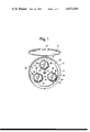
- FIG. 1 is a top view of the centrifugal drum polishing machine, embodying one form of the invention, showing the machine with the housing cover in an open position;
- FIG. 2 is a longitudinal section of the centrifugal drum polishing machine.
- the entire unit of a housing with access from the top and with a circular cross-section, for example, is identified by 10 with a cover 14 being articulated with its open top part 12 by means of hinge 16 in order to close this cover.
- the top housing part 12 is separated from the bottom housing part 18 by a horizontal false bottom 20.
- the lower housing part 18, in the zone of its lower edge, has an inside flange 22, for example, with props 24 being mounted on its underside at an angular distance from each other for the purpose of installation of the centrifugal drum machine.
- False bottom 20 serves as the support of a drum aggregate designed as a unit by 26, consisting of a drive motor 28, a rotor 30 and three holding containers 32, 34, 36 in each of which a removable drum container 28 is located.
- rotor 30 During operation of the centrifugal drum machine, rotor 30 and holding containers 32, 34, 36 rotate around vertical axes. In this process, rotor 30 is mounted with boss 40 on a driven shaft 42 of drive 44 of the drive motor 28, bolted to the underside of the support-forming false bottom 20, so that the drive motor together with its respective motor brake 46 is located in the lower housing part 18.
- the rotor has the form of an inverted dish and has a total of three bearing bosses 48 in which the respective holding container is mounted with its bearing shaft 54 by means of ball bearings 50, 52, so as to be freely rotatable, an impeller 56 being mounted with torsional resistance on the lower end of the bearing shaft projecting from boss 48 and carrying an elastic ring, particularly a rubber ring 58 on its circumference.
- a contact ring 60 is provided, which may be molded on it, and which has an internal curcumferential surface 62 of curcular-cylindrical shape as the running surface.
- the rubber rings 58 of impellers 56 contact this internal circumferential surface under pressure.
- An electrical switch located on the circumference of the lower housing part 18 in a depressed wall part 66 is designated by 64 as a unit, the operation of which allows starting of the drive motor 28.
- the latter drives rotor 30, during whose rotation the holding containers 32, 34, 36 for drum containers 38 move along a circular path. Because the impellers 56 are forced to roll on the running surface 62 of contact ring 60 during this process, the holding containers are placed into rotation around their own axes. Thus, they perform self-rotation during rotation of the rotor. This increases the centrifugal force acting on the charge and thus the grinding pressure in drum containers 38.
- a safety switch 68 is provided which can be operated by an actuating button 70 of cover 14 shown in closed position in FIG.
- cover 14 As long as cover 14 is in closed position, the circuit driving the drive motor 28 remains closed and the drum polishing machine remains in operation for a predetermined adjustable time. However, if cover 14 is opened, the circuit is disconnected by safety switch 68, so that inadvertent operation of switch 64 can not start the machine when the housing is open.
- the holding containers 32, 34, 36 are designed as polygon cylinders, preferably in hexagonal form. In their rotational motion, this design assures entrainment of the drum containers 38 having the same cross-section. The latter must simply be inserted from the top into the pot-like holding containers but do not need to be specifically mounted therein.
- a fairly large radial play a is provided between the wall of the holding containers and the drum containers, which effectively prevents upward travel of the drum containers 38 during operation of the centrifugal drum polisher.
- the drum containers are shown open, while in FIG. 1, they are closed with a cover 38' which can be reliably tightened on the holding container without leaks by means of a tightening device 39' operated with handwheel 39.
- FIG. 2 clearly shows the design of the inside bottom surface 72 of the drum containers, which exhibits an inverted dome shape favoring transport of the charge along the inside wall of the drum containers in upward direction during operation of the centrifugal drum polishing machine.
- housing top part 12 behind cover hinge 16 is provided with a stop 74, by means of which the cover is prevented from falling back in its open position.
Landscapes
- Engineering & Computer Science (AREA)
- Mechanical Engineering (AREA)
- Finish Polishing, Edge Sharpening, And Grinding By Specific Grinding Devices (AREA)
- Polishing Bodies And Polishing Tools (AREA)
- Centrifugal Separators (AREA)
Applications Claiming Priority (2)
| Application Number | Priority Date | Filing Date | Title |
|---|---|---|---|
| DE19762602055 DE2602055A1 (de) | 1976-01-21 | 1976-01-21 | Fliehkrafttrommelmaschine zur oberflaechenbehandlung von kleinteilen |
| DT2602055 | 1976-01-21 |
Publications (1)
| Publication Number | Publication Date |
|---|---|
| US4073095A true US4073095A (en) | 1978-02-14 |
Family
ID=5967870
Family Applications (1)
| Application Number | Title | Priority Date | Filing Date |
|---|---|---|---|
| US05/759,839 Expired - Lifetime US4073095A (en) | 1976-01-21 | 1977-01-17 | Centrifugal drum polishing machine |
Country Status (9)
| Country | Link |
|---|---|
| US (1) | US4073095A (de) |
| JP (1) | JPS52105400A (de) |
| AT (1) | AT345689B (de) |
| DE (1) | DE2602055A1 (de) |
| ES (1) | ES455260A1 (de) |
| FR (1) | FR2338771A1 (de) |
| GB (1) | GB1507812A (de) |
| IT (1) | IT1077566B (de) |
| NL (1) | NL7700238A (de) |
Cited By (14)
| Publication number | Priority date | Publication date | Assignee | Title |
|---|---|---|---|---|
| US4308693A (en) * | 1979-02-21 | 1982-01-05 | Harper Buffing Machine Co. | Barrel-finishing apparatus |
| US20020078813A1 (en) * | 2000-09-28 | 2002-06-27 | Hoffman Steve E. | Saw blade |
| US20020085959A1 (en) * | 1991-03-04 | 2002-07-04 | Glen Carey | Cuvette for an automated analyzer |
| US6599176B2 (en) * | 2001-09-27 | 2003-07-29 | Mikronite Technologies Group Inc. | High speed centrifugal processor |
| US20030176150A1 (en) * | 2001-09-27 | 2003-09-18 | Hoffman Steve E. | Tool fixtures for use in rotational processing |
| US20030194349A1 (en) * | 1991-03-04 | 2003-10-16 | Glen Carey | Fluid handling apparatus for an automated analyzer |
| US6733375B2 (en) | 2001-09-27 | 2004-05-11 | Mikronite Technologies Group Inc. | Horizontal finishing machine |
| US6863207B2 (en) | 2001-09-27 | 2005-03-08 | Mikronite Technologies Group Inc. | System for high speed centrifugal welding |
| US6875081B2 (en) | 2001-09-27 | 2005-04-05 | Mikronite Technologies Group Inc. | Method of manufacturing a tool using a rotational processing apparatus |
| US20050279430A1 (en) * | 2001-09-27 | 2005-12-22 | Mikronite Technologies Group, Inc. | Sub-surface enhanced gear |
| US20060013729A1 (en) * | 1991-02-14 | 2006-01-19 | Glen Carey | Fluid handling apparatus for an automated analyzer |
| US20060018782A1 (en) * | 2000-09-28 | 2006-01-26 | Mikronite Technologies Group, Inc. | Media mixture for improved residual compressive stress in a product |
| US20060046620A1 (en) * | 2004-08-26 | 2006-03-02 | Mikronite Technologies Group, Inc. | Process for forming spherical components |
| US8932108B2 (en) | 2010-04-19 | 2015-01-13 | International Business Machines Corporation | High speed barrel polishing device |
Families Citing this family (5)
| Publication number | Priority date | Publication date | Assignee | Title |
|---|---|---|---|---|
| DE3802701A1 (de) * | 1988-01-29 | 1989-09-14 | Roesler Roland Oberflaechen | Gleitschliffmaschine |
| DE4404122C1 (de) * | 1994-02-09 | 1995-07-20 | Dreher Manfrid Kg Dr Ing | Fliehkraft-Gleitschleifmaschine |
| RU2443535C2 (ru) * | 2009-02-04 | 2012-02-27 | Аркадий Петрович Сергиев | Реверсивное устройство для отделочной обработки |
| RU2627083C1 (ru) * | 2016-02-24 | 2017-08-03 | Федеральное государственное бюджетное образовательное учреждение высшего профессионального образования "Пензенский государственный университет" (ФГБОУ ВПО "Пензенский государственный университет") | Устройство для автоматизированного закрепления крышки и герметизации контейнера центробежно-планетарной установки |
| RU171460U1 (ru) * | 2016-03-17 | 2017-06-01 | Дмитрий Александрович Ружников | Устройство для вибрационной обработки деталей |
Citations (5)
| Publication number | Priority date | Publication date | Assignee | Title |
|---|---|---|---|---|
| US489202A (en) * | 1893-01-03 | Centrifugal ore separator | ||
| US3422577A (en) * | 1966-02-07 | 1969-01-21 | Southwestern Eng Co | Self-discharging finishing mill |
| US3524735A (en) * | 1966-04-16 | 1970-08-18 | Hans Oetiker | Apparatus for treating small objects by using rotating drums |
| US3609921A (en) * | 1970-01-09 | 1971-10-05 | Cecil A Foster | Tumbling mill |
| US3855740A (en) * | 1972-02-19 | 1974-12-24 | Tipton Mfg Co | Centrifugal barrel finishing apparatus having tiltable tubs |
-
1976
- 1976-01-21 DE DE19762602055 patent/DE2602055A1/de active Pending
-
1977
- 1977-01-11 IT IT19183/77A patent/IT1077566B/it active
- 1977-01-12 NL NL7700238A patent/NL7700238A/xx not_active Application Discontinuation
- 1977-01-13 AT AT17677A patent/AT345689B/de not_active IP Right Cessation
- 1977-01-17 US US05/759,839 patent/US4073095A/en not_active Expired - Lifetime
- 1977-01-18 GB GB1945/77A patent/GB1507812A/en not_active Expired
- 1977-01-20 JP JP447277A patent/JPS52105400A/ja active Pending
- 1977-01-20 FR FR7701528A patent/FR2338771A1/fr not_active Withdrawn
- 1977-01-21 ES ES455260A patent/ES455260A1/es not_active Expired
Patent Citations (5)
| Publication number | Priority date | Publication date | Assignee | Title |
|---|---|---|---|---|
| US489202A (en) * | 1893-01-03 | Centrifugal ore separator | ||
| US3422577A (en) * | 1966-02-07 | 1969-01-21 | Southwestern Eng Co | Self-discharging finishing mill |
| US3524735A (en) * | 1966-04-16 | 1970-08-18 | Hans Oetiker | Apparatus for treating small objects by using rotating drums |
| US3609921A (en) * | 1970-01-09 | 1971-10-05 | Cecil A Foster | Tumbling mill |
| US3855740A (en) * | 1972-02-19 | 1974-12-24 | Tipton Mfg Co | Centrifugal barrel finishing apparatus having tiltable tubs |
Cited By (19)
| Publication number | Priority date | Publication date | Assignee | Title |
|---|---|---|---|---|
| US4308693A (en) * | 1979-02-21 | 1982-01-05 | Harper Buffing Machine Co. | Barrel-finishing apparatus |
| US20060013729A1 (en) * | 1991-02-14 | 2006-01-19 | Glen Carey | Fluid handling apparatus for an automated analyzer |
| US20050266570A1 (en) * | 1991-03-04 | 2005-12-01 | Bayer Corporation | Cuvette for an automated analyzer |
| US20020085959A1 (en) * | 1991-03-04 | 2002-07-04 | Glen Carey | Cuvette for an automated analyzer |
| US7182912B2 (en) | 1991-03-04 | 2007-02-27 | Bayer Corporation | Fluid handling apparatus for an automated analyzer |
| US20030194349A1 (en) * | 1991-03-04 | 2003-10-16 | Glen Carey | Fluid handling apparatus for an automated analyzer |
| US20020078813A1 (en) * | 2000-09-28 | 2002-06-27 | Hoffman Steve E. | Saw blade |
| US20060018782A1 (en) * | 2000-09-28 | 2006-01-26 | Mikronite Technologies Group, Inc. | Media mixture for improved residual compressive stress in a product |
| US20030176150A1 (en) * | 2001-09-27 | 2003-09-18 | Hoffman Steve E. | Tool fixtures for use in rotational processing |
| US6875081B2 (en) | 2001-09-27 | 2005-04-05 | Mikronite Technologies Group Inc. | Method of manufacturing a tool using a rotational processing apparatus |
| US20050279430A1 (en) * | 2001-09-27 | 2005-12-22 | Mikronite Technologies Group, Inc. | Sub-surface enhanced gear |
| US6863207B2 (en) | 2001-09-27 | 2005-03-08 | Mikronite Technologies Group Inc. | System for high speed centrifugal welding |
| US6733375B2 (en) | 2001-09-27 | 2004-05-11 | Mikronite Technologies Group Inc. | Horizontal finishing machine |
| US7040209B2 (en) | 2001-09-27 | 2006-05-09 | Mikronite Technologies, Inc. | Tool fixtures for use in rotational processing |
| US6599176B2 (en) * | 2001-09-27 | 2003-07-29 | Mikronite Technologies Group Inc. | High speed centrifugal processor |
| US20060046620A1 (en) * | 2004-08-26 | 2006-03-02 | Mikronite Technologies Group, Inc. | Process for forming spherical components |
| US7273409B2 (en) | 2004-08-26 | 2007-09-25 | Mikronite Technologies Group, Inc. | Process for forming spherical components |
| US8932108B2 (en) | 2010-04-19 | 2015-01-13 | International Business Machines Corporation | High speed barrel polishing device |
| US9550266B2 (en) | 2010-04-19 | 2017-01-24 | International Business Machines Corporation | High speed barrel polishing device |
Also Published As
| Publication number | Publication date |
|---|---|
| ATA17677A (de) | 1978-01-15 |
| JPS52105400A (en) | 1977-09-03 |
| DE2602055A1 (de) | 1977-07-28 |
| NL7700238A (nl) | 1977-07-25 |
| GB1507812A (en) | 1978-04-19 |
| AT345689B (de) | 1978-09-25 |
| FR2338771A1 (fr) | 1977-08-19 |
| IT1077566B (it) | 1985-05-04 |
| ES455260A1 (es) | 1977-12-16 |
Similar Documents
| Publication | Publication Date | Title |
|---|---|---|
| US4073095A (en) | Centrifugal drum polishing machine | |
| US4846158A (en) | Hand type electric massage machine | |
| US2334172A (en) | Rubbing machine | |
| US3857206A (en) | Compound motion rubbing machine | |
| US3983035A (en) | Balancing device for a rotatable drum which may be eccentrically loaded | |
| US2715826A (en) | Combined washing machine and extractor | |
| US2751725A (en) | Orbital action rubbing machine | |
| GB1598399A (en) | Drum type automatic electric washing machine | |
| US2215288A (en) | Washing machine mechanism | |
| US2258244A (en) | Washing machine | |
| US2346669A (en) | Washing machine | |
| US2255505A (en) | Washing machine | |
| US2720771A (en) | Liquid circulating means for washing machines and the like | |
| US3135689A (en) | Dampener assembly | |
| US3520158A (en) | Washing machine | |
| US2871689A (en) | Clothes washing machine | |
| PL336218A1 (en) | Washing machine | |
| US2777314A (en) | Washing machine vapor seal | |
| KR940021412A (ko) | 용기 충전 장치(A Filling Machine for Vessels) | |
| US2622425A (en) | Self-contained agitator for washing clothes | |
| SU504556A1 (ru) | Конусна инерционна дробилка | |
| US2594936A (en) | Electrically driven machine for mixing and kneading or for mincing | |
| US2649705A (en) | Washing machine with coacting motor drive and drain control | |
| SU1717218A1 (ru) | Мельница | |
| US3534915A (en) | Ice crusher |