US405698A - Chimney cap and ventilator - Google Patents
Chimney cap and ventilator Download PDFInfo
- Publication number
- US405698A US405698A US405698DA US405698A US 405698 A US405698 A US 405698A US 405698D A US405698D A US 405698DA US 405698 A US405698 A US 405698A
- Authority
- US
- United States
- Prior art keywords
- pipe
- ventilator
- wheel
- chimney
- band
- Prior art date
- Legal status (The legal status is an assumption and is not a legal conclusion. Google has not performed a legal analysis and makes no representation as to the accuracy of the status listed.)
- Expired - Lifetime
Links
Images
Classifications
-
- F—MECHANICAL ENGINEERING; LIGHTING; HEATING; WEAPONS; BLASTING
- F23—COMBUSTION APPARATUS; COMBUSTION PROCESSES
- F23L—SUPPLYING AIR OR NON-COMBUSTIBLE LIQUIDS OR GASES TO COMBUSTION APPARATUS IN GENERAL ; VALVES OR DAMPERS SPECIALLY ADAPTED FOR CONTROLLING AIR SUPPLY OR DRAUGHT IN COMBUSTION APPARATUS; INDUCING DRAUGHT IN COMBUSTION APPARATUS; TOPS FOR CHIMNEYS OR VENTILATING SHAFTS; TERMINALS FOR FLUES
- F23L17/00—Inducing draught; Tops for chimneys or ventilating shafts; Terminals for flues
- F23L17/02—Tops for chimneys or ventilating shafts; Terminals for flues
Definitions
- IVILLIAM EARLE OF PHILADELPHIA, PENNSYLVANIA.
- My invention relates to improvements in chimney caps and ventilators; and the object of my invention is to furnish a chimney cap and ventilator which will, no matter in what direction the wind may be, always create a draft through the chimney.
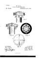
- Figure 1 is a side elevation of my chimney cap and ventilator; Fig. 2, a central sectional elevation of the same; Fig. 3, a section of Fig. 2 on line 1 2, and Fig. i a plan of Fig. 1.
- A is the pipe.
- a wheel B which is of slightly greater diameter than pipe A.
- the wheel B is inclosed in a metal cylinder D, which is open at the top and bottom, and which prevents the said wheel from being affected by horizontal current-s of air.
- E is the pivot upon which the wheel B is secured; F, the lower step for the pivot E, and which also forms the support for holding the cylinder D and the outside band G, the upper support for pivot E being the top I. (See Fig. 2.)
- H is a corrugated flange placed around the top of pipe A
- I is a corrugated conical piece, which is of somewhat less diameter than band G, and which forms the top for the whole device.
- the top I is furnished with corrugations b, which, while making it stiffer, assist in cansing a better dispersion of the smoke or gas.
- the outside band G is of sufficient Width, as shown in Fig. 2, to extend from the lower end of top I to below the top of flange H.
- This band prevents all wind from blowing directly across the top of pipe A, and causes all the air to be deflected. upward by the flange II.
Landscapes
- Engineering & Computer Science (AREA)
- Chemical & Material Sciences (AREA)
- Combustion & Propulsion (AREA)
- Mechanical Engineering (AREA)
- General Engineering & Computer Science (AREA)
- Devices Affording Protection Of Roads Or Walls For Sound Insulation (AREA)
Description
No Model.)
W. EARLE.
CHIMNEY GAP AND VENTILATOR.
No. 405,698. Patented June- 25, 1889.
WITN
UNITED STATES PATENT OFFICE.
IVILLIAM EARLE, OF PHILADELPHIA, PENNSYLVANIA.
CHIMNEY CAP AND VENTILATOR.
SPECIFICATION forming part of Letters Patent No. 405,698, dated June 25, 1889. Application filed May 1, 1888. Renewed March 18, 1889. Serial No. 303, 824, (No model.)
To all whom, z'l' may concern.-
Be it known that I, WILLIAM EARLE, a citizen of the United States, residing at Philadelphia, in the county of Philadelphia and State of Pennsylvania, have invented certain new and useful Improvements in Chimney Gaps and Ventilators, of which the following is a specification, reference being had therein to the accompanying drawings.
My invention relates to improvements in chimney caps and ventilators; and the object of my invention is to furnish a chimney cap and ventilator which will, no matter in what direction the wind may be, always create a draft through the chimney.
In the drawings, Figure 1 is a side elevation of my chimney cap and ventilator; Fig. 2, a central sectional elevation of the same; Fig. 3, a section of Fig. 2 on line 1 2, and Fig. i a plan of Fig. 1.
A is the pipe. Directly over this pipe is placed a wheel B, which is of slightly greater diameter than pipe A. The wheel B is inclosed in a metal cylinder D, which is open at the top and bottom, and which prevents the said wheel from being affected by horizontal current-s of air.
E is the pivot upon which the wheel B is secured; F, the lower step for the pivot E, and which also forms the support for holding the cylinder D and the outside band G, the upper support for pivot E being the top I. (See Fig. 2.)
H is a corrugated flange placed around the top of pipe A, and I is a corrugated conical piece, which is of somewhat less diameter than band G, and which forms the top for the whole device.
The wind in striking against the pipe A is forced up through the corrugationsa between the pipe and flange, as shown by the an rows in Fig. 2, and at the same time it passes between the corrugations upon the outside of the flange up to and through the wheel B, rapidly revolving this wheel and creating a great draft in the pipe A. The smoke or foul air, after passing out of pipe A, is dispersed by wheel B and passes out both from the bottom of band G and out of the space between this band and the top I.
The top I is furnished with corrugations b, which, while making it stiffer, assist in cansing a better dispersion of the smoke or gas.
The outside band G is of sufficient Width, as shown in Fig. 2, to extend from the lower end of top I to below the top of flange H.
This band prevents all wind from blowing directly across the top of pipe A, and causes all the air to be deflected. upward by the flange II.
Having thus described my invention, I claim and desire to secure by Letters Patent- 1. In combinationwith the pipe A, band G, wheel B, and top I, the corrugated flange H, adapted to deflect air both along its inside and outside to the top of pipe A, substantially as set forth.
2. The combination of pipe A, wheel B, carried on a pivot E, cylinderD, band Gr, corru gated flange H, and corrugated top I, all arranged and operating substantially as and for the purposes set forth.
In testimony whereof I affix my signature in the presence of two witnesses.
\VILLIAM EARLE.
IVitnesses:
GEORGE W. CLEMENT, IV M. T. IVIOALEES.
Publications (1)
| Publication Number | Publication Date |
|---|---|
| US405698A true US405698A (en) | 1889-06-25 |
Family
ID=2474647
Family Applications (1)
| Application Number | Title | Priority Date | Filing Date |
|---|---|---|---|
| US405698D Expired - Lifetime US405698A (en) | Chimney cap and ventilator |
Country Status (1)
| Country | Link |
|---|---|
| US (1) | US405698A (en) |
-
0
- US US405698D patent/US405698A/en not_active Expired - Lifetime
Similar Documents
| Publication | Publication Date | Title |
|---|---|---|
| US352597A (en) | Feedeeic w | |
| US405698A (en) | Chimney cap and ventilator | |
| US410660A (en) | Chimney-cowl | |
| US317294A (en) | caell | |
| US1162205A (en) | Ventilator. | |
| US481082A (en) | Exhaust-nozzle | |
| US1029072A (en) | Chimney-cap. | |
| US572415A (en) | Flue and smoke-stack protector | |
| US898790A (en) | Chimney cap and ventilator. | |
| US583847A (en) | Chimney-cowl | |
| US686404A (en) | Spark-arrester. | |
| US743390A (en) | Cowl. | |
| US101123A (en) | David hahn | |
| US555448A (en) | Chimney ventilator or cowl | |
| US480390A (en) | Spark-arrester | |
| US888728A (en) | Chimney-cowl. | |
| US201466A (en) | Improvement in chimney-caps | |
| US4487A (en) | Ventilator | |
| US1071951A (en) | Chimney, ventilator, and the like. | |
| US594877A (en) | James w | |
| US201641A (en) | Improvement in chimney-cowls | |
| US520368A (en) | Gael wilhelm johann martens | |
| US347394A (en) | Chimney-cap | |
| US1041616A (en) | Wind-operated ventilator. | |
| US395010A (en) | Chimney-top |