US4045668A - Method and apparatus for immiscible liquids measurement - Google Patents
Method and apparatus for immiscible liquids measurement Download PDFInfo
- Publication number
- US4045668A US4045668A US05/716,338 US71633876A US4045668A US 4045668 A US4045668 A US 4045668A US 71633876 A US71633876 A US 71633876A US 4045668 A US4045668 A US 4045668A
- Authority
- US
- United States
- Prior art keywords
- liquid
- fiber
- refractive index
- optical fiber
- oil
- Prior art date
- Legal status (The legal status is an assumption and is not a legal conclusion. Google has not performed a legal analysis and makes no representation as to the accuracy of the status listed.)
- Expired - Lifetime
Links
Images
Classifications
-
- G—PHYSICS
- G01—MEASURING; TESTING
- G01N—INVESTIGATING OR ANALYSING MATERIALS BY DETERMINING THEIR CHEMICAL OR PHYSICAL PROPERTIES
- G01N21/00—Investigating or analysing materials by the use of optical means, i.e. using sub-millimetre waves, infrared, visible or ultraviolet light
- G01N21/17—Systems in which incident light is modified in accordance with the properties of the material investigated
- G01N21/41—Refractivity; Phase-affecting properties, e.g. optical path length
- G01N21/43—Refractivity; Phase-affecting properties, e.g. optical path length by measuring critical angle
- G01N21/431—Dip refractometers, e.g. using optical fibres
-
- G—PHYSICS
- G01—MEASURING; TESTING
- G01F—MEASURING VOLUME, VOLUME FLOW, MASS FLOW OR LIQUID LEVEL; METERING BY VOLUME
- G01F1/00—Measuring the volume flow or mass flow of fluid or fluent solid material wherein the fluid passes through a meter in a continuous flow
- G01F1/74—Devices for measuring flow of a fluid or flow of a fluent solid material in suspension in another fluid
-
- G—PHYSICS
- G01—MEASURING; TESTING
- G01N—INVESTIGATING OR ANALYSING MATERIALS BY DETERMINING THEIR CHEMICAL OR PHYSICAL PROPERTIES
- G01N21/00—Investigating or analysing materials by the use of optical means, i.e. using sub-millimetre waves, infrared, visible or ultraviolet light
- G01N21/01—Arrangements or apparatus for facilitating the optical investigation
- G01N21/15—Preventing contamination of the components of the optical system or obstruction of the light path
- G01N2021/154—Ultrasonic cleaning
-
- Y—GENERAL TAGGING OF NEW TECHNOLOGICAL DEVELOPMENTS; GENERAL TAGGING OF CROSS-SECTIONAL TECHNOLOGIES SPANNING OVER SEVERAL SECTIONS OF THE IPC; TECHNICAL SUBJECTS COVERED BY FORMER USPC CROSS-REFERENCE ART COLLECTIONS [XRACs] AND DIGESTS
- Y10—TECHNICAL SUBJECTS COVERED BY FORMER USPC
- Y10S—TECHNICAL SUBJECTS COVERED BY FORMER USPC CROSS-REFERENCE ART COLLECTIONS [XRACs] AND DIGESTS
- Y10S250/00—Radiant energy
- Y10S250/90—Optical liquid level sensors
- Y10S250/904—Optical liquid level sensors with single light guide element to guide light in a continuous path
- Y10S250/905—Optical liquid level sensors with single light guide element to guide light in a continuous path with longitudinal irregularity
- Y10S250/907—Optical liquid level sensors with single light guide element to guide light in a continuous path with longitudinal irregularity with portions of light guide coating or cladding removed
Definitions
- the invention relates generally to the field of measurement of relative liquid percentages, and more particularly to measurement of the proportion of oil in water.
- the invention is generally applicable to measurement of the proportion of a first liquid dispersed in a lower refractive index second liquid with which the first is immiscible.
- a particular, but not necessarily exclusive application is the measurement of the presence of oil dispersed in water. Such measurements are required, for instance, for monitoring the discharge of ballast water from oil tenders. Other uses include monitoring tanker ballast water discharge.
- apparatus and a basic method for measuring the proportion of a first liquid dispersed in a lower refractive index second liquid with which the first is immiscible consist of monitoring the optical attenuation of a length of optical fiber having an unclad region immersed in the liquids dispersion, which unclad region has a refractive index greater than that of the second liquid but not more than 0.1 greater than that of the first liquid.
- the refractive index of the unclad region of fiber is either matched with, or is less than that of the first liquid.
- the light source is not necessarily an emitter in the visible part of the spectrum, it may alternatively be an IR or a UV emitter.
- the measurement may be carried out on a discrete quantity sampling basis, or on a continuous flow basis.
- the continuous flow measurement may be made on a sample part or a larger total flow.
- the invention also provides apparatus for measuring the proportion of a first liquid dispersed in a lower refractive index second liquid with which the first is immiscible, which apparatus includes an optical fiber threading a measurement chamber containing the liquids dispersion.
- the optical fiber in the measurement chamber includes an unclad region the core refractive index of which is greater than that of the second liquid but not more than 0.1 greater than that of the first liquid.
- a light energy source is included for launching light energy into one end of the fiber and a detector is arranged for measuring the quantity (intensity) of light transmitted through the fiber to the other end.
- the measurement chamber is replaced by a duct through which the liquids dispersion is caused to flow.
- the liquids dispersion is ultrasonically vibrated in the vicinity of the unclad region of the optical fiber as this tends to promote uniformity of the dispersion and prevent an unrepresentatively large accumulation of the first liquid adherent to the fiber.
- a feature of the present invention in its application to the measurement of oil in water is that it is comparatively insensitive to such variations in salinity as are likely to be encountered between the various ocean seas and coastal estuaries where there is fresh water dilution.
- this has the advantage of reducing the frequency with which the instrument has to be recalibrated as compared with other aforementioned instruments of the type which rely upon the use of ultra-violet fluorescense and infra-red absorption techniques.
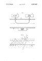
- FIG. 1 is a diagram illustrating the components of a measuring device according to the invention.
- FIG. 2 is a diagram illustrating how a globule of oil attached to the unclad region of fiber increases the fiber attenuation.
- the device of FIG. 1 consists essentially of a light source 10, a length of optical fiber 11, part of which threads through a pipe 12, and a calibrated optical detector 13. At least part of the length of that portion of the fiber threading the pipe 12 is unclad.
- the fiber has a refractive index greater than that of water but is either matched with or just less than that of the oil. When only water is present in the tube the water effectively acts as a cladding for the unclad length of fiber.
- FIG. 2 There a globule of oil 20 is shown attached to the surface of an unclad section of optical fiber 21 which is immersed in water 22. A ray 23 is shown as propagating down the fiber by total internal reflection at each point never striking the fiber/water interface 27.
- Rays 24 and 25 are propagating at the same angle to the axis as ray 23, and therefore, in the absence of the globule 20, would propagate down the fiber in the same manner as ray 23.
- the refractive index of the globule is greater than that of the fiber and hence rays 24 and 25 are refracted into the globule through the interface 27.
- rays 24 and 25 are refracted into the globule through the interface 27.
- Other rays, such as ray 26 may strike the globule/water interface at angles greater than the critical angle and hence be reflected.
- Some of these rays, such as ray 26, will therefore be reflected back into the fiber, but with an angle of incidence in the fiber less than the critical angle for the fiber/water interface, and hence will emerge from the side of the fiber opposite the globule. It will be appreciated however that some of the rays incident upon the globule will be reflected back into it at angles consistent with propagation down the fiber.
- the ray geometry depicted in FIG. 2 represents the situation where the refractive index of the oil globule is greater than that of the fiber. Under these conditions some light is refracted at the interface between the fiber and the globule and a small proportion is reflected. If however the refractive index of the fiber is matched with that of the oil the reflected component vanishes and light passes undeviated through the fiber/oil globule interface. If the refractive index of the oil is less than that of the fiber there will be a measure of optical guidance provided by the fiber/oil interface.
- the refractive index of the oil is greater than that of the water, this guidance is less than that provided by the fiber/water interface, and hence the presence of an oil globule attached to the fiber will still attenuate light propagating in the fiber. This attenuation will be less than for the matched case, and for this reason it is not preferred to use a fiber whose refractive index exceeds that of the oil by more than about 10 percent.
- Some means of cleaning the unclad region of fiber is normally in order to prevent an unrepresentatively large accumulation of oil on the fiber.
- One way of achieving this is to have a matched pair of pipes and fibers. Periodically the flow is transferred from one pipe to the other so that when one pipe is in use, the other may be flushed clean with a detergent mixture in preparation for its redeployment into the active water/oil mixture stream.
- An alternative method of cleaning involves placing one or more ultrasonic transducers 14 (FIG. 1) in the pipe in the vicinity of the fiber. This ultrasonic cleaning has the additional advantage of tending to promote a more uniform dispersion of the oil throughout the water.
- the light source may be a laser such as for example a gallium arsenide laser, or it may be a broad band spectral emitter such as a quartz halogen lamp.
- Silica is for many applications a suitable material from which to make the core of the optical fiber since its refractive index (1.45) lies significantly above that of pure water (1.33) or sea water (1.34 to 1.38) while being slightly below that of most mineral oils which typically have refractive indicies of at least 1.47. For some applications, however, it may be preferred to use optical fiber of plastics material of the types known in the fiber optics art.
- a set of fibers of different refractive index may be used and also the wavelength of the light propagating in the fiber may be selected from a particular part of the spectrum by filtering.
- a feature of the instrument is that, since an optical fiber is involved, the display part of the instrument can readily be linked by optical fiber to a distant sensor part of the instrument.
- the optical fiber link may be continuation of the sensor fiber. Such a continuation may normally be provided with a cladding layer.
- the ends of the measurement fiber may be coupler fibers selected for lower transmission loss. Separation of the source and the detector from the sensor is useful in applications in which, for safety reasons, it is desired to keep the voltage supplies for the optical source and detector far removed from the environment of the sensor.
- the sensitivity of the instrument can readily be of the order of a few parts per million of oil in water. For instance, using a 23 cm unclad length of 110 um diameter silica fiber propagating light from a HeNe laser operating at 6328 A, the detected power received at the far end of the fiber changed from 230 uW for pure water to 100 uW for water containing 100 parts per million dispersed oil of refractive index 1.4. Sensitivity can be increased not only by using a longer unclad length of fiber, but also by putting bends in the unclad region.
- the pipe 12 is replaced by a measurement chamber into which a discrete quantity of the liquids dispersion is dispensed for batch type measurement.
Landscapes
- Physics & Mathematics (AREA)
- General Physics & Mathematics (AREA)
- Fluid Mechanics (AREA)
- Health & Medical Sciences (AREA)
- Life Sciences & Earth Sciences (AREA)
- Chemical & Material Sciences (AREA)
- Analytical Chemistry (AREA)
- Biochemistry (AREA)
- General Health & Medical Sciences (AREA)
- Immunology (AREA)
- Pathology (AREA)
- Investigating Or Analysing Materials By Optical Means (AREA)
Applications Claiming Priority (2)
| Application Number | Priority Date | Filing Date | Title |
|---|---|---|---|
| GB34778/75A GB1507747A (en) | 1975-08-21 | 1975-08-21 | Immiscible liquids measurement |
| UK34778/75 | 1975-08-21 |
Publications (1)
| Publication Number | Publication Date |
|---|---|
| US4045668A true US4045668A (en) | 1977-08-30 |
Family
ID=10369835
Family Applications (1)
| Application Number | Title | Priority Date | Filing Date |
|---|---|---|---|
| US05/716,338 Expired - Lifetime US4045668A (en) | 1975-08-21 | 1976-08-20 | Method and apparatus for immiscible liquids measurement |
Country Status (20)
| Country | Link |
|---|---|
| US (1) | US4045668A (cg-RX-API-DMAC10.html) |
| JP (1) | JPS5226897A (cg-RX-API-DMAC10.html) |
| AU (1) | AU505122B2 (cg-RX-API-DMAC10.html) |
| BE (1) | BE845311A (cg-RX-API-DMAC10.html) |
| BR (1) | BR7605495A (cg-RX-API-DMAC10.html) |
| CA (1) | CA1062496A (cg-RX-API-DMAC10.html) |
| DD (1) | DD126512A5 (cg-RX-API-DMAC10.html) |
| DE (1) | DE2636215A1 (cg-RX-API-DMAC10.html) |
| DK (1) | DK375776A (cg-RX-API-DMAC10.html) |
| ES (1) | ES450848A1 (cg-RX-API-DMAC10.html) |
| FI (1) | FI762391A7 (cg-RX-API-DMAC10.html) |
| FR (1) | FR2321692A1 (cg-RX-API-DMAC10.html) |
| GB (1) | GB1507747A (cg-RX-API-DMAC10.html) |
| IL (1) | IL50275A (cg-RX-API-DMAC10.html) |
| IT (1) | IT1065116B (cg-RX-API-DMAC10.html) |
| NL (1) | NL7608468A (cg-RX-API-DMAC10.html) |
| NO (1) | NO762867L (cg-RX-API-DMAC10.html) |
| PT (1) | PT65499B (cg-RX-API-DMAC10.html) |
| SE (1) | SE7609213L (cg-RX-API-DMAC10.html) |
| ZA (1) | ZA764870B (cg-RX-API-DMAC10.html) |
Cited By (23)
| Publication number | Priority date | Publication date | Assignee | Title |
|---|---|---|---|---|
| US4159420A (en) * | 1976-12-18 | 1979-06-26 | Denki Kagaku Keiki Co., Ltd. | Apparatus for detecting oils and the like |
| US4187025A (en) * | 1977-07-01 | 1980-02-05 | Battelle Memorial Institute | Device for producing a light signal corresponding to the refractive index of a fluid |
| US4270049A (en) * | 1978-06-12 | 1981-05-26 | Ishikawajima-Harima Jukogyo Kabushiki Kaisha | Liquid leakage detection system |
| JPS5853739A (ja) * | 1981-09-04 | 1983-03-30 | ウエスチングハウス・エレクトリツク・コ−ポレ−シヨン | 光フアイバ式不純物検出装置 |
| US4386269A (en) * | 1979-11-15 | 1983-05-31 | Avon Rubber Company Limited | Method and device for detecting leaks from pipelines |
| DE3217168A1 (de) * | 1982-05-07 | 1983-11-17 | Fraunhofer-Gesellschaft zur Förderung der angewandten Forschung e.V., 8000 München | Faseroptisches refraktometer |
| US4462699A (en) * | 1981-09-10 | 1984-07-31 | Board Of Trustees Of The Leland Stanford Junior University | Fiber coupler temperature transducer |
| US4668870A (en) * | 1983-07-02 | 1987-05-26 | Diesel Kiki Co., Ltd. | Refrigerant level sensor in receiver tank |
| US4708941A (en) * | 1985-03-07 | 1987-11-24 | The United States Of America As Represented By The Secretary Of The Navy | Optical waveguide sensor for methane gas |
| US4711126A (en) * | 1985-03-13 | 1987-12-08 | 501 Nederlandse Centrale Organisatie Voor Toegepast-Enschappelijk Onderzoek | Sensor for the measurement of the refractive index of a fluid and/or phase boundary between two fluids by means of visible or invisible light |
| US5164608A (en) * | 1991-06-27 | 1992-11-17 | Hughes Aircraft Company | Plural wavelength fiber optic liquid level sensor for multiple liquids |
| US5187366A (en) * | 1991-06-25 | 1993-02-16 | Joram Hopenfeld | Sensors for detecting leaks |
| US5200615A (en) * | 1991-06-25 | 1993-04-06 | Joram Hopenfeld | Method and apparatus for detecting the presence of fluids |
| US5334850A (en) * | 1991-10-17 | 1994-08-02 | Sumitomo Chemical Co., Ltd. | Method and device for optically detecting an interface between two fluids and method of setting the parameters for such detection |
| WO2000048023A1 (en) * | 1999-02-10 | 2000-08-17 | Waters Investments Limited | Flow cell, analyte measurement apparatus and methods related thereto |
| US6205820B1 (en) * | 1992-09-04 | 2001-03-27 | Corning Incorporated | Process for improving adhesive attachment |
| US6422073B1 (en) * | 1996-08-09 | 2002-07-23 | Siemens Elema Ab | Device for identifying liquid anaesthetics |
| US20050046826A1 (en) * | 2002-02-26 | 2005-03-03 | Bsh Bosch Und Siemens Hausgerate Gmbh | Apparatus for checking the formation of scale, and water-carrying appliance |
| US20070131297A1 (en) * | 2005-12-12 | 2007-06-14 | Spaolonzi Mauricio P | Leak detection system and method for offshore hose lines |
| US20080199351A1 (en) * | 2007-02-15 | 2008-08-21 | Airocare, Inc. | Zero yield reactor and method of sanitizing air using zero yield reactor |
| WO2011128406A1 (en) * | 2010-04-14 | 2011-10-20 | Advanced Sensors Limited | Imaging apparatus |
| CN109290940A (zh) * | 2017-07-24 | 2019-02-01 | 株式会社荏原制作所 | 研磨装置及研磨方法 |
| US11524754B2 (en) * | 2016-06-29 | 2022-12-13 | Koninklijke Philips N.V. | Light guides with low refractive coating to be used in water |
Families Citing this family (4)
| Publication number | Priority date | Publication date | Assignee | Title |
|---|---|---|---|---|
| JPS5722103Y2 (cg-RX-API-DMAC10.html) * | 1977-06-10 | 1982-05-13 | ||
| JPS5476785U (cg-RX-API-DMAC10.html) * | 1977-11-09 | 1979-05-31 | ||
| DE3247659A1 (de) * | 1982-12-23 | 1984-06-28 | Wolfgang Dr. 7000 Stuttgart Ruhrmann | Optischer sensor |
| DE4038354C2 (de) * | 1990-12-01 | 1994-06-30 | Bruker Analytische Messtechnik | ATR-Meßsonde |
Citations (3)
| Publication number | Priority date | Publication date | Assignee | Title |
|---|---|---|---|---|
| US3448616A (en) * | 1967-06-29 | 1969-06-10 | Sinclair Research Inc | Liquid level detector |
| US3553666A (en) * | 1969-04-15 | 1971-01-05 | Illinois Tool Works | Remote sensing indicator device |
| US3834235A (en) * | 1971-12-17 | 1974-09-10 | M Bouton | Liquid and solid sensing device |
Family Cites Families (1)
| Publication number | Priority date | Publication date | Assignee | Title |
|---|---|---|---|---|
| US3513319A (en) * | 1968-02-19 | 1970-05-19 | Phillips Petroleum Co | Refractometer having spaced light conducting rods |
-
1975
- 1975-08-21 GB GB34778/75A patent/GB1507747A/en not_active Expired
-
1976
- 1976-07-30 NL NL7608468A patent/NL7608468A/xx not_active Application Discontinuation
- 1976-08-06 AU AU16650/76A patent/AU505122B2/en not_active Expired
- 1976-08-12 ZA ZA764870A patent/ZA764870B/xx unknown
- 1976-08-12 DE DE19762636215 patent/DE2636215A1/de not_active Withdrawn
- 1976-08-16 IL IL50275A patent/IL50275A/xx unknown
- 1976-08-19 DD DD194398A patent/DD126512A5/xx unknown
- 1976-08-19 IT IT26372/76A patent/IT1065116B/it active
- 1976-08-19 BE BE2055255A patent/BE845311A/xx unknown
- 1976-08-19 SE SE7609213A patent/SE7609213L/xx unknown
- 1976-08-20 FR FR7625341A patent/FR2321692A1/fr active Granted
- 1976-08-20 BR BR7605495A patent/BR7605495A/pt unknown
- 1976-08-20 PT PT65499A patent/PT65499B/pt unknown
- 1976-08-20 DK DK375776A patent/DK375776A/da not_active Application Discontinuation
- 1976-08-20 FI FI762391A patent/FI762391A7/fi not_active Application Discontinuation
- 1976-08-20 JP JP51098798A patent/JPS5226897A/ja active Pending
- 1976-08-20 ES ES450848A patent/ES450848A1/es not_active Expired
- 1976-08-20 CA CA259,568A patent/CA1062496A/en not_active Expired
- 1976-08-20 US US05/716,338 patent/US4045668A/en not_active Expired - Lifetime
- 1976-08-20 NO NO762867A patent/NO762867L/no unknown
Patent Citations (3)
| Publication number | Priority date | Publication date | Assignee | Title |
|---|---|---|---|---|
| US3448616A (en) * | 1967-06-29 | 1969-06-10 | Sinclair Research Inc | Liquid level detector |
| US3553666A (en) * | 1969-04-15 | 1971-01-05 | Illinois Tool Works | Remote sensing indicator device |
| US3834235A (en) * | 1971-12-17 | 1974-09-10 | M Bouton | Liquid and solid sensing device |
Cited By (29)
| Publication number | Priority date | Publication date | Assignee | Title |
|---|---|---|---|---|
| US4159420A (en) * | 1976-12-18 | 1979-06-26 | Denki Kagaku Keiki Co., Ltd. | Apparatus for detecting oils and the like |
| US4187025A (en) * | 1977-07-01 | 1980-02-05 | Battelle Memorial Institute | Device for producing a light signal corresponding to the refractive index of a fluid |
| US4270049A (en) * | 1978-06-12 | 1981-05-26 | Ishikawajima-Harima Jukogyo Kabushiki Kaisha | Liquid leakage detection system |
| US4386269A (en) * | 1979-11-15 | 1983-05-31 | Avon Rubber Company Limited | Method and device for detecting leaks from pipelines |
| JPS5853739A (ja) * | 1981-09-04 | 1983-03-30 | ウエスチングハウス・エレクトリツク・コ−ポレ−シヨン | 光フアイバ式不純物検出装置 |
| US4462699A (en) * | 1981-09-10 | 1984-07-31 | Board Of Trustees Of The Leland Stanford Junior University | Fiber coupler temperature transducer |
| DE3217168A1 (de) * | 1982-05-07 | 1983-11-17 | Fraunhofer-Gesellschaft zur Förderung der angewandten Forschung e.V., 8000 München | Faseroptisches refraktometer |
| US4668870A (en) * | 1983-07-02 | 1987-05-26 | Diesel Kiki Co., Ltd. | Refrigerant level sensor in receiver tank |
| US4708941A (en) * | 1985-03-07 | 1987-11-24 | The United States Of America As Represented By The Secretary Of The Navy | Optical waveguide sensor for methane gas |
| US4711126A (en) * | 1985-03-13 | 1987-12-08 | 501 Nederlandse Centrale Organisatie Voor Toegepast-Enschappelijk Onderzoek | Sensor for the measurement of the refractive index of a fluid and/or phase boundary between two fluids by means of visible or invisible light |
| US5187366A (en) * | 1991-06-25 | 1993-02-16 | Joram Hopenfeld | Sensors for detecting leaks |
| US5200615A (en) * | 1991-06-25 | 1993-04-06 | Joram Hopenfeld | Method and apparatus for detecting the presence of fluids |
| US5164608A (en) * | 1991-06-27 | 1992-11-17 | Hughes Aircraft Company | Plural wavelength fiber optic liquid level sensor for multiple liquids |
| US5334850A (en) * | 1991-10-17 | 1994-08-02 | Sumitomo Chemical Co., Ltd. | Method and device for optically detecting an interface between two fluids and method of setting the parameters for such detection |
| US6205820B1 (en) * | 1992-09-04 | 2001-03-27 | Corning Incorporated | Process for improving adhesive attachment |
| US6422073B1 (en) * | 1996-08-09 | 2002-07-23 | Siemens Elema Ab | Device for identifying liquid anaesthetics |
| WO2000048023A1 (en) * | 1999-02-10 | 2000-08-17 | Waters Investments Limited | Flow cell, analyte measurement apparatus and methods related thereto |
| US6188813B1 (en) * | 1999-02-10 | 2001-02-13 | Waters Investments Limited | Flow cell, analyte measurement apparatus and methods related thereto |
| US6526188B2 (en) * | 1999-02-10 | 2003-02-25 | Waters Investments Limited | Flow cell, analyte measurement apparatus and methods related thereto |
| US20050046826A1 (en) * | 2002-02-26 | 2005-03-03 | Bsh Bosch Und Siemens Hausgerate Gmbh | Apparatus for checking the formation of scale, and water-carrying appliance |
| US7162896B2 (en) * | 2002-02-26 | 2007-01-16 | Bsh Bosch Und Siemens Hausgeraete Gmbh | Apparatus for checking the formation of scale, and water-carrying appliance |
| US20070131297A1 (en) * | 2005-12-12 | 2007-06-14 | Spaolonzi Mauricio P | Leak detection system and method for offshore hose lines |
| US7453367B2 (en) * | 2005-12-12 | 2008-11-18 | Veyance Technologies, Inc. | Leak detection system and method for offshore hose lines |
| US20080199351A1 (en) * | 2007-02-15 | 2008-08-21 | Airocare, Inc. | Zero yield reactor and method of sanitizing air using zero yield reactor |
| WO2011128406A1 (en) * | 2010-04-14 | 2011-10-20 | Advanced Sensors Limited | Imaging apparatus |
| US11524754B2 (en) * | 2016-06-29 | 2022-12-13 | Koninklijke Philips N.V. | Light guides with low refractive coating to be used in water |
| CN109290940A (zh) * | 2017-07-24 | 2019-02-01 | 株式会社荏原制作所 | 研磨装置及研磨方法 |
| CN109290940B (zh) * | 2017-07-24 | 2022-03-15 | 株式会社荏原制作所 | 研磨装置及研磨方法 |
| US11911867B2 (en) * | 2017-07-24 | 2024-02-27 | Ebara Corporation | Polishing apparatus and polishing method |
Also Published As
| Publication number | Publication date |
|---|---|
| DE2636215A1 (de) | 1977-03-03 |
| DK375776A (da) | 1977-02-22 |
| FR2321692A1 (fr) | 1977-03-18 |
| FI762391A7 (cg-RX-API-DMAC10.html) | 1977-02-22 |
| PT65499B (en) | 1978-02-13 |
| ZA764870B (en) | 1977-07-27 |
| GB1507747A (en) | 1978-04-19 |
| BR7605495A (pt) | 1977-08-16 |
| PT65499A (en) | 1976-09-01 |
| IL50275A0 (en) | 1976-10-31 |
| IT1065116B (it) | 1985-02-25 |
| FR2321692B1 (cg-RX-API-DMAC10.html) | 1980-03-21 |
| IL50275A (en) | 1979-03-12 |
| AU1665076A (en) | 1978-02-09 |
| JPS5226897A (en) | 1977-02-28 |
| ES450848A1 (es) | 1977-08-16 |
| NL7608468A (nl) | 1977-02-23 |
| DD126512A5 (cg-RX-API-DMAC10.html) | 1977-07-20 |
| AU505122B2 (en) | 1979-11-08 |
| SE7609213L (sv) | 1977-02-22 |
| BE845311A (nl) | 1977-02-21 |
| CA1062496A (en) | 1979-09-18 |
| NO762867L (cg-RX-API-DMAC10.html) | 1977-02-22 |
Similar Documents
| Publication | Publication Date | Title |
|---|---|---|
| US4045668A (en) | Method and apparatus for immiscible liquids measurement | |
| JP3660685B2 (ja) | 減衰全反射検出 | |
| JP4937231B2 (ja) | 微量種の分光測定のための光ファイバ共振器における拡張されたエバネッセントフィールド露出の方法と装置 | |
| US4753530A (en) | Analytical optical instruments | |
| JP2557353B2 (ja) | 光学装置 | |
| CN1625680B (zh) | 基于光纤的腔环降光谱装置 | |
| US5604587A (en) | Long capillary waveguide raman cell | |
| JPS622138A (ja) | 流体媒質の光吸収を測定する方法と装置 | |
| US4893894A (en) | Evanescent sensor | |
| JPS6156449B2 (cg-RX-API-DMAC10.html) | ||
| MXPA97002263A (en) | Attenuated total reflectance sensing | |
| CN101128730A (zh) | 光纤谐振器中表面等离子体谐振的光腔衰荡检测法 | |
| Yeoh et al. | Plastic fiber evanescent sensor in measurement of turbidity | |
| US6842234B2 (en) | Apparatus for measuring soot content in diesel engine oil in real time | |
| KR910021572A (ko) | 광섬유 연료 및 액체 게이지 | |
| JP3895434B2 (ja) | 分子吸収分光用の管状減衰光波センサ | |
| EP0886135B1 (en) | NIR absorbance measuring instrument with ATR probe | |
| KR810000796B1 (ko) | 혼합되지 않은 용액의 분산비율 측정장치 | |
| Tubb et al. | Single mode optical fibre surface plasma wave chemical sensor | |
| JPS5995439A (ja) | 腐食速度測定方法 | |
| Mendoza et al. | Embeddable distributed moisture and pH sensors for nondestructive inspection of aircraft lap joints | |
| US5224188A (en) | Eccentric core optical fiber | |
| CA2039079A1 (en) | Eccentric core optical fiber | |
| RU2083972C1 (ru) | Устройство индикации загрязнения сточных вод нефтепродуктами | |
| EP0062443A1 (en) | Sensitive optical fibres |