US4037390A - Device for side delivery of crop, grass or grain - Google Patents
Device for side delivery of crop, grass or grain Download PDFInfo
- Publication number
- US4037390A US4037390A US05/665,615 US66561576A US4037390A US 4037390 A US4037390 A US 4037390A US 66561576 A US66561576 A US 66561576A US 4037390 A US4037390 A US 4037390A
- Authority
- US
- United States
- Prior art keywords
- conveyor belt
- accordance
- crop
- pair
- pulleys
- Prior art date
- Legal status (The legal status is an assumption and is not a legal conclusion. Google has not performed a legal analysis and makes no representation as to the accuracy of the status listed.)
- Expired - Lifetime
Links
- 244000025254 Cannabis sativa Species 0.000 title claims abstract description 12
- 230000000694 effects Effects 0.000 claims description 7
- 230000000717 retained effect Effects 0.000 claims 2
- 230000008878 coupling Effects 0.000 claims 1
- 238000010168 coupling process Methods 0.000 claims 1
- 238000005859 coupling reaction Methods 0.000 claims 1
- 230000002441 reversible effect Effects 0.000 claims 1
- 239000000463 material Substances 0.000 abstract description 2
- 241001494496 Leersia Species 0.000 description 4
- 239000000853 adhesive Substances 0.000 description 3
- 230000001070 adhesive effect Effects 0.000 description 3
- 238000000151 deposition Methods 0.000 description 3
- 241001417527 Pempheridae Species 0.000 description 2
- 230000005484 gravity Effects 0.000 description 2
- 239000002245 particle Substances 0.000 description 2
- 238000007788 roughening Methods 0.000 description 2
- 238000010408 sweeping Methods 0.000 description 2
- 241001124569 Lycaenidae Species 0.000 description 1
- 230000009286 beneficial effect Effects 0.000 description 1
- 230000015572 biosynthetic process Effects 0.000 description 1
- 210000001520 comb Anatomy 0.000 description 1
- 238000010276 construction Methods 0.000 description 1
- 230000001627 detrimental effect Effects 0.000 description 1
- 238000006073 displacement reaction Methods 0.000 description 1
- 238000001035 drying Methods 0.000 description 1
- 230000009191 jumping Effects 0.000 description 1
- 230000002265 prevention Effects 0.000 description 1
- 239000004576 sand Substances 0.000 description 1
- 239000002689 soil Substances 0.000 description 1
- 239000004575 stone Substances 0.000 description 1
Images


Classifications
-
- A—HUMAN NECESSITIES
- A01—AGRICULTURE; FORESTRY; ANIMAL HUSBANDRY; HUNTING; TRAPPING; FISHING
- A01D—HARVESTING; MOWING
- A01D43/00—Mowers combined with apparatus performing additional operations while mowing
- A01D43/02—Mowers combined with apparatus performing additional operations while mowing with rakes
-
- A—HUMAN NECESSITIES
- A01—AGRICULTURE; FORESTRY; ANIMAL HUSBANDRY; HUNTING; TRAPPING; FISHING
- A01D—HARVESTING; MOWING
- A01D34/00—Mowers; Mowing apparatus of harvesters
- A01D34/835—Mowers; Mowing apparatus of harvesters specially adapted for particular purposes
- A01D34/86—Mowers; Mowing apparatus of harvesters specially adapted for particular purposes for use on sloping ground, e.g. on embankments or in ditches
-
- A—HUMAN NECESSITIES
- A01—AGRICULTURE; FORESTRY; ANIMAL HUSBANDRY; HUNTING; TRAPPING; FISHING
- A01D—HARVESTING; MOWING
- A01D57/00—Delivering mechanisms for harvesters or mowers
- A01D57/20—Delivering mechanisms for harvesters or mowers with conveyor belts
Definitions
- the invention relates to a device for side delivery of crops, grass or grain that is adapted for use with flail type harvesters, reel mowers, rotary mowers set at an angle towards the front, rotary tedders and reel tedders. All these machines raise the picked-up crop, grain or grass from the ground and throw it in an arc to the rear.
- transverse conveyor belts which are arranged behind the implements across the full width in a substantially vertical plane are known from German Patent Specifications No. 203,972, No. 416,981 and No. 652,455 for mowing machinery. These devices are designed to convey the grain to one side directly after cutting, to turn it over at the same time and deposit it, as required, in a swath. In order to be able to pick up the grain which is still upright after cutting, the transverse conveyor belts are arranged directly behind the cutter or table connected thereto. The cut grain is in contact with the ground here.
- hay-making after cutting of the grain is always carried out by means of two machines under present standards.
- One type of machine is designed to scatter the swath; the second type of machine serves to collect the scattered grain and to form a swath.
- the first type incorporates fork tedders, reel tedders and rotary tedders. All these machines work such that their rotating implements (fingers) lift the freshly mown or already part-dried grain off the ground and throw through the air with a more or less salient throw component, the grain being opened up and falling loosely to the ground, fanned out to a fairly wide degree.
- Collecting to form a swath overnight or after sufficient drying for loading onto a wagon or feeding a press is carried out almost always by means of a finger-wheel rake, a machine having several finger wheels which are arranged in staggered fashion behind one another and partly intersect in the direction of travel. Said finger wheels shift aside the grain lying on the ground in such a manner that the grain picked up by the foremost finger wheel is conveyed to the next wheel and from there to the one behind, the grain finally being deposited in the form of a swath behind the rearmost and last finger wheel.
- the finger wheels of this machine are either driven positively by the power take-off of the tractor towing them or are caused to rotate as they are pulled across the ground.
- finger-wheel rakes One disadvantage of finger-wheel rakes is that the fingers attached to the wheels have to come close to the ground or even project into it, meaning that they damage the turf as they move across the field; they get bent or even break off as they strike objects on the ground and tear out particles of earth as they shift the grain aside.
- side delivery rakes of this kind require a great deal of room and are relatively heavy, the finger wheels running very erratically and often jumping, especially when they are driven at high speed as they are pulled across the ground.
- the object is to design the side rake required for gathering swaths in the form of an attachment for tedders of the type always found on farms, which attachment can be made lighter, used for a wider variety of applications and picks up the grain in the air and shifts it aside at a certain distance from the ground and hence largely free from particles of earth.
- transverse conveyor belt or belts is/are arranged within the tossing region of the implements, which pick up the cut grain off the ground and throw it to the rear, and can be driven at speeds producing a pick-up effect until reaching one of the two end pulleys.
- the transverse conveyor belts are arranged within the tossing region of the implements, i.e., at a predetermined distance from the implements, the grain tossed up to the rear by the implements acting as tedders is thrown against the carrying side or front run of the transverse conveyor belt, to which it sticks until it reaches the belt end pulley where it drops off as the belt starts to return, then lying on the ground in the form of a swath for example.
- the transverse conveyor belt can be used whereever the implements of mower or hay-making machine are caused to turn quickly and operate in such a manner that they lift the grain up directly after cutting, or directly off the ground by means of the current of air for example, throwing the grain either directly afterwards or simultaneously to the rear; the grain travels through a particular trajectory at the peak of which you arrange the transverse conveyor belts.
- Typical agricultural machines suitable for this purpose comprise flail mowers, reel mowers, rotary mowers set at an angle toward the front, rotary tedders and reel tedders. All these machines raise the pick-up grains and throw it in an arc to the rear.
- the flail mower raises the cut grain between a covering hood and a reel. On reaching the end of the covering hood, the picked-up grain has such kinetic energy that it has a horizontal throw component.
- the parts of greater specific gravity such as lumps of soil, stones and sand drop back onto the ground immediately whereas the grain of lower specific gravity is picked up by the moving belt as a result of the high throwing speed and the steady flow of grain from the front.
- transverse conveyor belt is driven at a speed producing a pick-up effect at the delivery end, meaning that directional depositing in the form of a swath for example is possible without damp grain in particular sticking to the return side or back run of the belt.
- the adhesive capacity of the belt can be raised by roughening, especially by outward projecting fingers or vertically arranged ribs, ridges or tabs.
- the transverse conveyor belt may be combined with a flail mower or rotary mower, although it may also be designed as a trailer, extending transversely to a longitudinal member and supported by its own wheels.
- a transverse conveyor belt of this kind may also be used in conjunction with a brush turning about a horizontal axis on road sweepers or snow blowers.
- the plane in which the belt moves as well as its speed of movement are variable. Although the grass or grain thrown at the belt stick to it when the latter is moving at the right speed, and is carried along to the end pulley when the belt is arranged vertically, the adhesive capacity can be increased by making the belt move in a plane which is slightly off vertical at the top in the rearward direction. An increase in the speed of the belt also enables - especially if the belt has projecting fingers or ribs - the grass or grain to be thrown further away and scattered out by the throwing action of the fingers or ribs at the point of turn-around of the belt, instead of the grain being gathered into a swath.
- the resultant range of scatter can be made even greater when the side conveyor belt consists of several parts, i.e. when several conveyor belts are arranged above one another and can be driven by end pulleys of different diameters, meaning that the grass or grain is ejected by each of the transverse conveyor belts with throw components of differing magnitude.
- FIG. 1 is a top view of a flail mower and transverse conveyor belt situated behind it, which mower is saddle-mounted and attached pivotably to one side of the tractor track;
- FIG. 2 shows a section along line II--II from FIG. 1;
- FIG. 3 shows a rear view along line III--III from FIG. 1, the equipment being used as a slope-type mower;
- FIG. 4 is a top view of a rotor mower which is operating behind and to one side of the tractor and has a large working width and a transverse conveyor belt situated behind it;
- FIG. 5 shows a rear view in the direction of arrow V from FIG. 4;
- FIG. 6 is a section through a pair of end pulleys for two transverse conveyor belts arranged above one another;
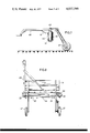
- FIG. 7 is a side view of a transverse conveyor belt taking the form of a trailer attachment supported by its own ground wheels;
- FIG. 8 is a top view of the device according to FIG. 7.
- FIG. 1 shows the rear part of a tractor 1 with a three-point linkage 2 and with a support 3.
- a frame 4 is secured to the rear side of the support 3 suitable for sliding lateral displacement by means of a hydraulic cylinder 7 supported against the support 3.
- the frame 4 carries at its right side two pivot pins 5 in horizontal tandem arrangement in travel direction for a pivotal connection of a flail type harvester 6.
- This flail type harvester 6 can be raised or lowered towards the ground by means of a further hydraulic cylinder 8.
- the flail shaft or rotor 9 of the flail type harvester carries pivotally connected knives 16 at its periphery and is driven by the P.T.O 10 of the tractor through a cardan shaft 11, a belt drive 12 and an universal joint 13. Both ends of the flail shaft or rotor 9 are adjustably mounted in bearings at the left and right sidewall 14, 15 respectively of the flail type harvester, whereas the left shaft end in travel direction is coupled to the driven end of the universal joint 13 which is secured to the left sidewall 14.
- a flail knife 16 extends radially outwardly by the centrifugal force, so that their ends describe the cutting circle 17.
- the crop or grain which is previously deflected forwardly in travel direction 19 by deflector means is cut by the rotating flails and is moved by the fan effect of the flails via the upper half of the cutting circle 17 and afterwards in a rearwardly directed airstream which is limited by the inner housing 56 of the hood which functions as baffle plate, as shown in FIG. 2.
- this airstream is slightly directed downwardly.
- Transverse conveyor belt 20 of thin, flexible material is located near the exit of the housing 56 and thus within the tossing region of the implements across the full width thereof.
- This transverse conveyor belt 20 is adjustable in its inclination relative to the ground and is adjustable in its distance to the flail type harvester, functioning as a side delivery device.
- the conveyor belt is supported by a beam 24 and runs around two end pulleys 21, 22 one of which is driven through a clutch 26 by a hydromotor 27.
- the grain tossed up to the rear by the implements of the flail type harvester is thrown against the carrying side or front run of the transverse conveyor belt and is conveyed with reference to the rotating direction of the hydromotor 27 either in direction of the arrow 28 in FIG. 1 rearwards of the tractor or in direction of the arrow 29 towards the right side of the flail type harvester, then lying on the ground.
- the axis of the end pulleys 21, 22 are located vertically but can be angular adjustable at an angle X towards the ground. Additionally the conveyor belt 20 can be arranged within different distances of the flail shaft or rotor 9 by using one of several connecting holes 25 to permit adaption to the stream curve of the rearwardly tossed crop or grain.
- Windrowing behind the tractor during rotation of the conveyor belt 20 in the direction of the arrow 28 is supported by a curved deflector plate 30. Behind the conveyor belt 20 a plate 32 bent downwardly is mounted as a device for accident prevention.
- FIG. 3 shows the use of the transverse conveyor belt in conjunction with the mowing of overgrown slopes with a flail type harvester.
- the cut crop, grain or grass is conveyed over the upper or the lower edge of the slope where it is deposited either behind the tractor or at the bottom side of the slope and where it can be collected on plane grounds.
- the adhesive capacity of the belt can be raised by roughening, especially by outward projecting strips, fingers, tines, ribs, bars, combs or similar projections.
- the conveyor belt 38 is used behind a rotor mower 33.
- the knives 34 rotating around vertical shafts 35 in the direction of the arrows 36 describe three touching cutting circles, along said cutting circles with reference to the direction of travel of the machine the crop is cut.
- the shaft 40 is driven by a belt drive 41 running between the end pulleys 40 or 39 and a gear unit 13.
- the conveyor belt 38 is running around the end pulleys 39, 40 in a crossed position of 180°.
- each half of the carrying side or front run of the conveyor belt moves the tossed crop or grain either to the side or to the center.
- the left half of the conveyor belt conveys the crop in the direction of the arrow 42 to the right side and the right half of the conveyor belt conveys it in the direction of the arrow 43 to the left side, so that the crop is deposited without interference on the ground in the middle of and behind the machine.
- the rotary direction of the driven end pulleys 40 the crop is deposited at both ends of the pulleys.
- the peripheries of the end pulleys 39, 40 are slightly spherically shaped.
- each of said belts runs around end pulleys 45, 46 of different diameter, whereas the upper pair of end pulleys 45 has a larger diameter than the lower pair of end pulleys 46, so that the crop or grain is ejected by each of the conveyor belts with throw components of differing magnitude.
- Each conveyor belt is provided with a coordinated guiding plate 31, 31.
- the transverse conveyor belt 20 is arranged in a trailer coupled behind a harvester machine of any construction for side delivery of crop, hay, grain or grass directly after cutting, or directly off the ground by means of a laterally arranged deflecting plate.
- a deflecting plate can be arranged similar to the deflecting plate 30 in FIG. 1. It is only necessary for the utilization of such a trailer that the conveyor belt receives the crop or grain having a horizontal throw component. This is normally the case when flail type mowers, rotary mowers and rotary tedders are used. In this type of harvester machines the crop or grain is tossed upwardly and bridges a certain stretch or predetermined distance before it drops on the ground.
- the horizontal throw component can be fully utilized when the transverse conveyor belt is connected behind the implements in a suitable distance via a connecting rod 48 to the harvester machine.
- the trailer is supported by ground wheels 47.
- the conveyor belt is driven by one of the ground wheels 47 using a gear unit 49 for driving the end pulleys.
- This drive is independent from the drive of the harvester unit so that it need not be clutched when coupled or decoupled with the harvester unit, and this it is relatively easy to be handled.
- By reversing the movement of the gear unit 49 a left or right hand delivery of the crop or grain is easily to be achieved. It is also possible to deposit the grain in the center of such a trailer by crossing the belts.
- the drive for the conveyor belt can be derived from the P.T.O. 10 in order to be independent of the travel speed.
Landscapes
- Life Sciences & Earth Sciences (AREA)
- Environmental Sciences (AREA)
- Harvester Elements (AREA)
Applications Claiming Priority (2)
| Application Number | Priority Date | Filing Date | Title |
|---|---|---|---|
| NL7503295A NL7503295A (nl) | 1975-03-19 | 1975-03-19 | Gewasafvoer inrichting. |
| NL7503295 | 1975-03-19 |
Publications (1)
| Publication Number | Publication Date |
|---|---|
| US4037390A true US4037390A (en) | 1977-07-26 |
Family
ID=19823414
Family Applications (1)
| Application Number | Title | Priority Date | Filing Date |
|---|---|---|---|
| US05/665,615 Expired - Lifetime US4037390A (en) | 1975-03-19 | 1976-03-10 | Device for side delivery of crop, grass or grain |
Country Status (7)
| Country | Link |
|---|---|
| US (1) | US4037390A (cg-RX-API-DMAC10.html) |
| AU (1) | AU1208476A (cg-RX-API-DMAC10.html) |
| BE (1) | BE839707A (cg-RX-API-DMAC10.html) |
| CA (1) | CA1040871A (cg-RX-API-DMAC10.html) |
| DE (1) | DE2606151A1 (cg-RX-API-DMAC10.html) |
| FR (1) | FR2304270A1 (cg-RX-API-DMAC10.html) |
| NL (1) | NL7503295A (cg-RX-API-DMAC10.html) |
Cited By (15)
| Publication number | Priority date | Publication date | Assignee | Title |
|---|---|---|---|---|
| US4244163A (en) * | 1978-03-10 | 1981-01-13 | Kuhn, S.A. | Device for reducing the width of windrows formed by a mower |
| US4275547A (en) * | 1978-06-20 | 1981-06-30 | Multinorm, B.V. | Mowing device |
| US4341061A (en) * | 1979-11-28 | 1982-07-27 | Warren Denzin | Reel-type stubble conditioning device |
| US4344275A (en) * | 1980-01-11 | 1982-08-17 | Kateman Wilhelmus G M | Mushroom harvesting machine |
| US4590751A (en) * | 1984-06-20 | 1986-05-27 | Deere & Company | Double windrowing attachment for harvester |
| US4757672A (en) * | 1982-01-29 | 1988-07-19 | Deere & Company | Mower conditioner with double windrowing attachment |
| US5351468A (en) * | 1993-03-31 | 1994-10-04 | Joel Pominville | Selectable windrowing mower attachment and method of mounting |
| WO1999055138A1 (en) * | 1998-04-29 | 1999-11-04 | Keith Broomhall | Mowing machine |
| US20030024228A1 (en) * | 2001-08-04 | 2003-02-06 | Deere & Company, A Delaware Corporation | Windrow merging attachment |
| FR2855011A1 (fr) * | 2003-05-22 | 2004-11-26 | Kuhn Sa | Faucheuse munie d'un element de fermeture couvrant un mecanisme de regroupement d'andains |
| ITBO20100515A1 (it) * | 2010-08-06 | 2012-02-07 | Hymach S R L | Carcassa di protezione per dispositivo tosaerba |
| ITRM20100683A1 (it) * | 2010-12-22 | 2012-06-23 | Bruno Aliscioni | "trinciasarmenti sbracciata ad elevata versatilita', particolarmente utile per essere trainata da macchine o trattori per la pulizia degli argini e dei fossati presenti adiacentemente alle carreggiate stradali" |
| US20130192957A1 (en) * | 2012-01-31 | 2013-08-01 | Loewen Welding & Manufacturing Ltd. | Apparatus for loading material |
| US8997307B2 (en) | 2010-12-22 | 2015-04-07 | Loewen Welding & Manufacturing Ltd. | Apparatus for collecting material from a surface |
| US20150271994A1 (en) * | 2014-03-31 | 2015-10-01 | Kai S. Lee | Operationally tiltable counter rotating twin blade mowing deck |
Families Citing this family (7)
| Publication number | Priority date | Publication date | Assignee | Title |
|---|---|---|---|---|
| DK145211C (da) * | 1980-06-12 | 1983-03-07 | Taarup As Maskinfab | Hoestmaskine,navnlig groenthoester |
| FR2559344B1 (fr) * | 1984-02-10 | 1986-11-28 | Bucher Guyer Ag Masch | Machine a recolter le fourrage avec transport lateral |
| DE3604691A1 (de) * | 1986-02-14 | 1987-08-20 | Claas Saulgau Gmbh | Maehwerk mit querfoerderband |
| CH692121A5 (de) * | 1997-06-26 | 2002-02-28 | Mueller Gleisbau | Böschungsmähkopf. |
| GB9727083D0 (en) * | 1997-12-23 | 1998-02-18 | Kverneland Taarup As | Mower for cutting standing crop |
| FR3119509B1 (fr) * | 2021-02-10 | 2023-06-16 | Kuhn S A S | Machine agricole du type faucheuse |
| CN115486259B (zh) * | 2022-10-31 | 2023-05-30 | 广州市绿化有限公司 | 一种基于传动结构的园林草坪修剪装置 |
Citations (4)
| Publication number | Priority date | Publication date | Assignee | Title |
|---|---|---|---|---|
| US1269987A (en) * | 1916-09-06 | 1918-06-18 | Frederick O Werden | Lumber-piler. |
| US3402534A (en) * | 1965-06-28 | 1968-09-24 | Int Harvester Co | Forage crop harvester |
| US3665686A (en) * | 1969-08-14 | 1972-05-30 | Thomson Mach Co | Two row window harvester |
| US3696598A (en) * | 1968-04-19 | 1972-10-10 | Ernst Weichel | Apparatus for collecting crops |
-
1975
- 1975-03-19 NL NL7503295A patent/NL7503295A/xx not_active Application Discontinuation
-
1976
- 1976-02-17 DE DE19762606151 patent/DE2606151A1/de active Pending
- 1976-03-10 US US05/665,615 patent/US4037390A/en not_active Expired - Lifetime
- 1976-03-15 FR FR7607331A patent/FR2304270A1/fr active Granted
- 1976-03-16 CA CA248,013A patent/CA1040871A/en not_active Expired
- 1976-03-17 AU AU12084/76A patent/AU1208476A/en not_active Expired
- 1976-03-18 BE BE165279A patent/BE839707A/xx unknown
Patent Citations (4)
| Publication number | Priority date | Publication date | Assignee | Title |
|---|---|---|---|---|
| US1269987A (en) * | 1916-09-06 | 1918-06-18 | Frederick O Werden | Lumber-piler. |
| US3402534A (en) * | 1965-06-28 | 1968-09-24 | Int Harvester Co | Forage crop harvester |
| US3696598A (en) * | 1968-04-19 | 1972-10-10 | Ernst Weichel | Apparatus for collecting crops |
| US3665686A (en) * | 1969-08-14 | 1972-05-30 | Thomson Mach Co | Two row window harvester |
Cited By (18)
| Publication number | Priority date | Publication date | Assignee | Title |
|---|---|---|---|---|
| US4244163A (en) * | 1978-03-10 | 1981-01-13 | Kuhn, S.A. | Device for reducing the width of windrows formed by a mower |
| US4275547A (en) * | 1978-06-20 | 1981-06-30 | Multinorm, B.V. | Mowing device |
| US4341061A (en) * | 1979-11-28 | 1982-07-27 | Warren Denzin | Reel-type stubble conditioning device |
| US4344275A (en) * | 1980-01-11 | 1982-08-17 | Kateman Wilhelmus G M | Mushroom harvesting machine |
| US4757672A (en) * | 1982-01-29 | 1988-07-19 | Deere & Company | Mower conditioner with double windrowing attachment |
| US4590751A (en) * | 1984-06-20 | 1986-05-27 | Deere & Company | Double windrowing attachment for harvester |
| US5351468A (en) * | 1993-03-31 | 1994-10-04 | Joel Pominville | Selectable windrowing mower attachment and method of mounting |
| WO1999055138A1 (en) * | 1998-04-29 | 1999-11-04 | Keith Broomhall | Mowing machine |
| US20030024228A1 (en) * | 2001-08-04 | 2003-02-06 | Deere & Company, A Delaware Corporation | Windrow merging attachment |
| US6862873B2 (en) * | 2001-08-04 | 2005-03-08 | Deere & Company | Windrow merging attachment |
| FR2855011A1 (fr) * | 2003-05-22 | 2004-11-26 | Kuhn Sa | Faucheuse munie d'un element de fermeture couvrant un mecanisme de regroupement d'andains |
| ITBO20100515A1 (it) * | 2010-08-06 | 2012-02-07 | Hymach S R L | Carcassa di protezione per dispositivo tosaerba |
| ITRM20100683A1 (it) * | 2010-12-22 | 2012-06-23 | Bruno Aliscioni | "trinciasarmenti sbracciata ad elevata versatilita', particolarmente utile per essere trainata da macchine o trattori per la pulizia degli argini e dei fossati presenti adiacentemente alle carreggiate stradali" |
| US8997307B2 (en) | 2010-12-22 | 2015-04-07 | Loewen Welding & Manufacturing Ltd. | Apparatus for collecting material from a surface |
| US20130192957A1 (en) * | 2012-01-31 | 2013-08-01 | Loewen Welding & Manufacturing Ltd. | Apparatus for loading material |
| US9598248B2 (en) * | 2012-01-31 | 2017-03-21 | Loewen Welding & Manufacturing Ltd. | Apparatus for loading material |
| US20150271994A1 (en) * | 2014-03-31 | 2015-10-01 | Kai S. Lee | Operationally tiltable counter rotating twin blade mowing deck |
| US9867332B2 (en) * | 2014-03-31 | 2018-01-16 | Kai S. Lee | Operationally tiltable counter rotating twin blade mowing deck |
Also Published As
| Publication number | Publication date |
|---|---|
| DE2606151A1 (de) | 1976-09-30 |
| CA1040871A (en) | 1978-10-24 |
| FR2304270A1 (fr) | 1976-10-15 |
| BE839707A (fr) | 1976-07-16 |
| FR2304270B3 (cg-RX-API-DMAC10.html) | 1978-12-08 |
| AU1208476A (en) | 1977-09-22 |
| NL7503295A (nl) | 1976-09-21 |
Similar Documents
| Publication | Publication Date | Title |
|---|---|---|
| US4037390A (en) | Device for side delivery of crop, grass or grain | |
| US7418811B2 (en) | Mid mount rakes and pickup with side delivery swathers | |
| US3224177A (en) | Method of cutting, conditioning and windrowing a crop | |
| EP0558437B1 (en) | Mower for grass crops | |
| DE102018116297B3 (de) | Landwirtschaftliche Vorrichtung | |
| EP0715804B1 (en) | A machine for processing crop lying on the soil | |
| US4395868A (en) | Haymaking machine | |
| US3693331A (en) | Windrow leaf scavenger | |
| US20250098588A1 (en) | Pick-up attachment for a preferably self-propelled forage harvester | |
| EP0439991A1 (en) | A side discharger for a windrower | |
| US3523412A (en) | Harvester pickup attachment | |
| US2770937A (en) | Method of harvesting and curing forage crops | |
| US3797216A (en) | Crop pick-up mechanism | |
| CA1097085A (en) | Deflector means for mower-conditioner | |
| US2654209A (en) | Harvester pickup | |
| US3521439A (en) | Apparatus for harvesting cereal grains,leafy vegetables,or hoed vegetables | |
| US20070022725A1 (en) | Cutting device for taking care of lawns and the countryside comprising a device for receiving and comminuting cut items | |
| US11259465B2 (en) | Impeller with auger for an agricultural machine | |
| US2766576A (en) | Device for picking up cut crop or other material lying on the ground | |
| US3306017A (en) | Apparatus for topping sugar beets and saving the severed tops | |
| CN109964559A (zh) | 残膜捡拾回收装置 | |
| US12446491B2 (en) | Swath lifter | |
| US2753676A (en) | Pick-up and feed for harvester | |
| US5083978A (en) | Potato harvester and method | |
| US5131217A (en) | Mechanical harvester |
Legal Events
| Date | Code | Title | Description |
|---|---|---|---|
| AS | Assignment |
Owner name: PLASMA ENERGY CORPORATION, RTE. 8, BOX 114-Z, UMST Free format text: ASSIGNMENT OF ASSIGNORS INTEREST.;ASSIGNOR:TECHNOLOGY APPLICATION SERVICES CORPORATION;REEL/FRAME:004103/0965 Effective date: 19830222 |