US4030375A - Derailleur for bicycle - Google Patents
Derailleur for bicycle Download PDFInfo
- Publication number
- US4030375A US4030375A US05/672,528 US67252876A US4030375A US 4030375 A US4030375 A US 4030375A US 67252876 A US67252876 A US 67252876A US 4030375 A US4030375 A US 4030375A
- Authority
- US
- United States
- Prior art keywords
- cam plate
- pin
- derailleur according
- movable
- linkage members
- Prior art date
- Legal status (The legal status is an assumption and is not a legal conclusion. Google has not performed a legal analysis and makes no representation as to the accuracy of the status listed.)
- Expired - Lifetime
Links
- 238000010276 construction Methods 0.000 description 4
- 210000001331 nose Anatomy 0.000 description 3
- 230000008602 contraction Effects 0.000 description 2
- 230000000694 effects Effects 0.000 description 2
- 210000000887 face Anatomy 0.000 description 2
- 230000015572 biosynthetic process Effects 0.000 description 1
- 230000007547 defect Effects 0.000 description 1
- 238000006073 displacement reaction Methods 0.000 description 1
- 230000000717 retained effect Effects 0.000 description 1
Images


Classifications
-
- B—PERFORMING OPERATIONS; TRANSPORTING
- B62—LAND VEHICLES FOR TRAVELLING OTHERWISE THAN ON RAILS
- B62M—RIDER PROPULSION OF WHEELED VEHICLES OR SLEDGES; POWERED PROPULSION OF SLEDGES OR SINGLE-TRACK CYCLES; TRANSMISSIONS SPECIALLY ADAPTED FOR SUCH VEHICLES
- B62M9/00—Transmissions characterised by use of an endless chain, belt, or the like
- B62M9/04—Transmissions characterised by use of an endless chain, belt, or the like of changeable ratio
- B62M9/06—Transmissions characterised by use of an endless chain, belt, or the like of changeable ratio using a single chain, belt, or the like
- B62M9/10—Transmissions characterised by use of an endless chain, belt, or the like of changeable ratio using a single chain, belt, or the like involving different-sized wheels, e.g. rear sprocket chain wheels selectively engaged by the chain, belt, or the like
- B62M9/12—Transmissions characterised by use of an endless chain, belt, or the like of changeable ratio using a single chain, belt, or the like involving different-sized wheels, e.g. rear sprocket chain wheels selectively engaged by the chain, belt, or the like the chain, belt, or the like being laterally shiftable, e.g. using a rear derailleur
- B62M9/121—Rear derailleurs
- B62M9/124—Mechanisms for shifting laterally
- B62M9/1244—Mechanisms for shifting laterally limiting or positioning the movement
- B62M9/1246—Mechanisms for shifting laterally limiting or positioning the movement using cams or plates
Definitions
- This invention relates to a derailleur for a bicycle and more particularly to a derailleur used together with a multi-speed free wheel comprising a plurality, normally three to five of toothed sprockets attached to a rear hub of the bicycle, which derailleur is adapted to shift a driving chain to a selective one of the sprockets.
- this kind of derailleur is, as shown in U.K. patent specification No. 888,511 and U.K. patent specification No. 982,986, composed of a fitting member mounted to a bicycle frame, parallel linkage members pivoted to the fitting member, a movable member having chain-guide pulleys pivoted to the parallel linkage members, and a return spring unidirectionally urging the movable member.
- the derailleur effects the bicycle speed change in the following manner a control lever pulls a control wire for swinging the movable member against the return spring, or for restoring the member, by means of the spring restoration so that the drive chain on the guide pulleys may be shifted to a selective one of the sprockets of the multi-speed free wheel.
- a well known derailleur has no mechanism capable of positioning the guide pulleys in each speed change stage.
- the positioning should, in the speed change by the lever, depend upon the operator's sensibility only. Accordingly, in the chain shifting, an excessive or shortened lever turn causes a guide cage to be improper in its action to result in unexact speed-change. Hence, there is a defect that the chain hits the sprocket and produces a noise. Also, the operator controls the lever in response to the noise as a clue for adjusting the guide cage to a proper position. Such control requires a certain amount of skill.
- U.S. Pat. No. 3,362,238 and U.S. Pat. No. 3,394,604 suggest that at the control lever or a lever-holder thereof there are provided engageable holes having intervals corresponding to the speed change stage respectively and a ball engageable with the holes respectively so that the speed change stage may be defined.
- the ball is so engaged with the hole that the derailleur can be mechanically positioned at a proper speed-change stage to result in a theoretically accurate speed-change operation.
- the derailleur is operated by the lever through the control wire, occurrence of surplus extension of the wire or contraction of the outer cable may cause the movable member of the derailleur to be out of order, resulting in inaccurate speed-change operation.
- a main object of the invention is to provide a derailleur capable of always exactly shifting the drive chain by correcting the lever's improper action, i.e., somewhat excessive or shortened lever turn, and of being kept in its speed-change position.
- Another object of the invention is to provide a derailleur capable of correcting surplus extension of the wire or contraction of the outer cable with respect to the wire so that the chain may be exactly shifted.
- Still another object is to provide a derailleur simple in construction, applicable to a conventional lever and shiftable of the drive chain by means of a single wire with attendance of obtaining the above purposes.
- the present invention is characterized in that a cam plate having a retainer for the control wire is pivoted to one of four members constituting the derailleur, i.e., a first mounting member, a second and third linkage members, and a fourth movable member, and in that to another member movable relative to the member with the pivoted cam plate is fixed a pin engageable with the cam face of the cam plate.
- FIG. 1 is a front view of the derailleur of the invention, which has the cam plate mounted to the linkage members and the pin to the mounting member,
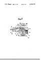
- FIG. 2 is a bottom view thereof
- FIG. 3 is a bottom view of the derailleur in FIGS. 1 and 2, showing its controlled condition
- FIG. 4 is an enlarged plan view of the cam plate only
- FIG. 5 is a bottom view of the derailleur provided with the cam plate attached to the movable member and the pin to the linkage member, and
- FIG. 6 is a bottom view of the derailleur having the cam plate attached to the mounting member and the pin to the linkage member.
- the derailleur of the invention is, as shown in FIGS. 1 through 3 and FIGS. 5 and 6, basically composed of four members, such as, a first fitting member 1, and second and third two parallel linkage members 5 and 6, and a fourth movable member 9.
- the fitting member 1 comprises a bracket 1a fixed to a fork end (not shown) together with a hub shift (not shown) of a bicycle and a fitting body 1b mounted to the bracket 1a through a pivot 2 in movable relation in a given range.
- the body 1b is rotatable with respect to the bracket 1a but is in rigid non-rotatable relation with the movable member 9.
- the body 1b is provided at one side thereof with opposite noses to which two linkage member 5 and 6 are pivotally supported at each one end thereof through two pins 3 and 4.
- the linkage members 5 and 6 equal in length and of a C-like shape section respectively, are mounted to the body 1b of the fitting member opposite to each outer at end open side of the same. At the foremost ends of the linkage members is pivotally supported the movable member 9 through pins 7 and 8.
- the movable member 9 is formed substantially similarly to the body 1b, which has at one side thereof two opposite noses pivotally supporting the linkage member 5 and 6 therebetween through the pins 7 and 8 in the relationship that both the movable member and the linkage members are swingingly movable with each other.
- At the other side of the movable member 9 are mounted cages 11 carrying two chain-guide pulleys 10 therebetween through a pivot in rotatable relation in a given range only respectively.
- the chain-guide pulleys 10 serve to carry a driving chain (not shown) thereon and move in the axial direction of the multi-speed transmitting freewheel (not shown) so that the chain may be introduced from the pulleys to a selective sprocket of the freewheel to be in engagement therewith for changing the speed of the bicycle.
- the invention is directed to provide in the derailleur constructed as aforegoing a positioning device described hereinafter between two members relatively movable with respect each other during its speed-change operation, namely, between; the fitting member 1 and the movable member 9 or the linkage member 5 or 6; the movable member 9 and the linkage member 5 or 6, or the two linkage members 5 and 6.
- the positioning device serves to selectively determine the proper position where the chain-guide pulleys 10 are to be kept during speed-change operation, and comprises a cam plate 12 having a cam face 20 formed of notches 20a, 20b, 20c, 20d and 20e which corresponds to the number of the speed change stages.
- the linkage member 6 projects, as shown in FIGS. 2 and 3, at its middle portion towards the opposite linkage member 5 to form a tongue 6a for mounting the cam plate 12 therewith.
- the body 1b is, as shown in FIGS. 2 and 3, extended at its one side, i.e., at the bottom nose, towards the movable member 9, which extension 1c is positioned at its tip nearby the cam plate 12, the mounting tongue 6a at the linkage member 6 being provided with the cam plate 12 through the pivot 13 in rotatable relation with the tongue 6a.
- the cam plate 12 is, as shown in FIGS. 2 and 3, provided at its one end opposite to the pivot 13 with a retainer 14 for the control wire a.
- the retainer 14 is, as is well known, composed of a bolt having at its middle portion a hole through which the wire extends and a nut, and is located at one swingable end portion of the cam plate around the pivot 13 for the operation of the control wire a.
- Each of the arced faces 20a to 20e is spaced from the center of the pivot 13 in the following manner that a distance l 1 between the first notch 20aand the pivot 13 is the shortest as the base, from which l 1 distances l 2 , l 3 , l 4 , and l 5 , are sequentially increased in length corresponding to the displacement degree in the bicycle speed change respectively, where each of the notches 2ato 20e is connected with each other through a face of a slant line.
- the cam face 20 may, as shown in FIGS. 2, 3 and 4, be formed at the inner face of an elongated curved hole larger in width than the outer diameter of the pin 15, or formed at the outer end face of the cam plate 12.
- the pin 15 is fixed to the extension 1c of the tongue of the body 1b of the fitting member 1, projects towards the cam plate 12, comes in contact at the lengthwise middle portion of the pin with the cam face 20, and is selectively engaged with the notches 20a to 20e respectively.
- the reference numeral 16 denotes a return spring surrounding the pivot 13, the return spring 16 being retained at its one end to the linkage member 6 and at the other end to a stopper 17 provided at the cam plate 12.
- the reference numeral 18 denotes a retainer for the outer cable b, which is non-rotatably mounted to the body 1b.
- a control lever (not shown) is turned to pull the wire a for changing the bicycle speed so that the cam plate 12 swings around the pivot to allow the cam face 20 to shift its portion in contact with the pin 15 from, for example, the first notch 2a to the second notch 20b, wherein the distance 1 2 between the pivot 13 and the second notch 20b is larger than the distance l 1 between the former and the first notch 20a, so that the linkage member 6 having the cam plate 12 pivoted thereto is forced to swing.
- the other linkage member 5 and the movable member 9 swing so that a drive chain (not shown) may be shifted to a desirable sprocket through the guide cages 11 for changing the bicycle speed.
- the slant faces connecting each of the notches 20a to 20e are brought into contact with the pin 15 for moving the guide cages 11 through the linkage member 6.
- the pin 15 transfers from the slant face to the next notch, that is, the pin rides on the next notch, for example, the second notch 20b, the linkage member 6 cannot swing so far as the pin is not engageable with the following slant face even though the cam plate 12 continues to swing within the range of the length the notch 20b.
- the derailleur is idling during the time the pin 15 is in contact with the latter until it shifts to the following slant face so that the cyclist may clearly judge the pin 15 is in contact with the notch 20b, whereby the drive chain may properly be positioned to a selective sprocket of the freewheel.
- the cam plate 12 is mounted to the linkage member 6 and the pin 15 to the fitting member 1. Also, the cam plate may be mounted to the movable member 9 and the pin 15 to the linkage member 5. Further the cam plate 12 may, as shown in FIG. 6, be mounted to the fitting member and the pin 15 to the linkage member 5.
- the cam plate 12 may be mounted to the linkage member 5 opposite the linkage member 6.
- the pin 15 may be fixed to the movable member 9 or one of the linkage members 6 or 5 opposite to other linkage members 5 or 6, provided with the cam plate, other than the fitting member 1 as shown in FIGS. 1 to 3.
- the cam plate 12 is, as shown in FIG. 5, mounted to the movable member 9, the pin 15 may be mounted to the other linkage member 6 or the fitting member 1 other than the one linkage member 5.
- the cam plate 12 is, as shown in FIG.
- the pin 15 may be mounted to the other linkage member 6 or the movable member 9 other than the one linkage member 5.
- the cam plate 12 is, as shown in FIG. 5, mounted to the movable member 9, the latter is partially extended to the middle portion of the linkage member 6 to form an extension of which an idle end rotatably pivotally supports the cam plate 12 as aforesaid.
- the cam plate 12 is, as shown in FIG. 6, mounted to the fitting member 1, the fitting body 1b is partially extended towards the movable member 9 to form an extension 1d which is positioned at its tip in the middle portion of the linkage member 6 to be pivoted with the cam plate 12 through the pivot 13.
- the derailleur of the invention effects the bicycle speed change by turning the cam plate to shift the cam face in contact with the pin so that the movable member may travel. Therefore, the cam face formation, which step by step corresponds to the speed change stages, makes it possible to change the bicycle speed gradually in divided steps with each of the speed change stages.
- the speed change operation may be carried out accurately and exactly and further the cam face is formed of notches having a given length respectively so that the operation may always be proper regardless of the extension of the operating wire thereby obtaining constantly proper speed change operation.
Landscapes
- Engineering & Computer Science (AREA)
- Chemical & Material Sciences (AREA)
- Combustion & Propulsion (AREA)
- Transportation (AREA)
- Mechanical Engineering (AREA)
- Transmissions By Endless Flexible Members (AREA)
- Transmission Devices (AREA)
- Gear-Shifting Mechanisms (AREA)
Applications Claiming Priority (2)
| Application Number | Priority Date | Filing Date | Title |
|---|---|---|---|
| JA50-43619 | 1975-04-09 | ||
| JP50043619A JPS51118237A (en) | 1975-04-09 | 1975-04-09 | Outside speed change mechanism |
Publications (1)
| Publication Number | Publication Date |
|---|---|
| US4030375A true US4030375A (en) | 1977-06-21 |
Family
ID=12668845
Family Applications (1)
| Application Number | Title | Priority Date | Filing Date |
|---|---|---|---|
| US05/672,528 Expired - Lifetime US4030375A (en) | 1975-04-09 | 1976-03-31 | Derailleur for bicycle |
Country Status (5)
| Country | Link |
|---|---|
| US (1) | US4030375A (enExample) |
| JP (1) | JPS51118237A (enExample) |
| FR (1) | FR2306867A1 (enExample) |
| GB (1) | GB1533436A (enExample) |
| IT (1) | IT1071259B (enExample) |
Cited By (23)
| Publication number | Priority date | Publication date | Assignee | Title |
|---|---|---|---|---|
| US4106356A (en) * | 1976-01-12 | 1978-08-15 | Shimano Industrial Company Limited | Derailer for a bicycle |
| DE2907741A1 (de) * | 1978-02-28 | 1979-08-30 | Shimano Industrial Co | Umwerfer fuer eine fahrrad-kettenschaltung |
| DE2834646A1 (de) * | 1978-08-08 | 1980-02-21 | Fichtel & Sachs Ag | Kettenschaltung mit gangvorwahl |
| US4194409A (en) * | 1977-07-12 | 1980-03-25 | Shimano Industrial Company Limited | Front derailleur for a bicycle provided with a swingingly movable chain guide |
| US4198874A (en) * | 1977-05-20 | 1980-04-22 | Shimano Industrial Company Limited | Derailleur for bicycles and similar vehicles |
| US4241617A (en) * | 1975-10-13 | 1980-12-30 | Shimano Industrial Company Limited | Derailleur for a bicycle |
| FR2463716A1 (fr) * | 1979-08-17 | 1981-02-27 | Fichtel & Sachs Ag | Derailleur pour bicyclettes |
| EP0020092A3 (en) * | 1979-05-24 | 1981-05-06 | Shimano Industrial Company Limited | Cycle derailleur |
| US4362523A (en) * | 1979-08-08 | 1982-12-07 | Huret & Ses Fils | Derailleur for a cycle |
| US4378222A (en) * | 1979-08-17 | 1983-03-29 | Fichtel & Sachs Ag | Derailler system for a bicycle |
| US4437848A (en) | 1980-03-15 | 1984-03-20 | Shimano Industrial Company Limited | Derailleur for a bicycle |
| US4460347A (en) * | 1979-10-26 | 1984-07-17 | Fichtel & Sachs Ag | Mechanism for adjusting the position of a bicycle chain |
| USRE31796E (en) * | 1977-05-20 | 1985-01-08 | Shimano Industrial Company Limited | Derailleur for bicycles and similar vehicles |
| US4507101A (en) * | 1982-04-07 | 1985-03-26 | Shimano Industrial Company Limited | Speed control device for a bicycle |
| US4954121A (en) * | 1988-07-12 | 1990-09-04 | Simplex, S.A. | Rear derailleur for bicycles or similar vehicles |
| US5897451A (en) * | 1997-04-29 | 1999-04-27 | Shimano, Inc. | Bicycle derailleur having operating forces disposed on opposite sides of a link pivot |
| US5961409A (en) * | 1996-12-26 | 1999-10-05 | Shimano, Inc. | Rear derailleur for a bicycle |
| US20060135301A1 (en) * | 2004-12-20 | 2006-06-22 | Shimano Inc. | Rear derailleur for bicycle |
| US9033833B2 (en) | 2011-01-28 | 2015-05-19 | Paha Designs, Llc | Gear transmission and derailleur system |
| US9163707B2 (en) | 2011-09-30 | 2015-10-20 | Mtd Products Inc | Method for controlling the speed of a self-propelled walk-behind lawn mower |
| US9327792B2 (en) | 2011-01-28 | 2016-05-03 | Paha Designs, Llc | Gear transmission and derailleur system |
| US9334018B2 (en) * | 2014-07-28 | 2016-05-10 | Shimano Inc. | Bicycle derailleur |
| US20160318582A1 (en) * | 2011-01-28 | 2016-11-03 | Paha Designs, Llc | Gear transmission and derailleur system |
Families Citing this family (7)
| Publication number | Priority date | Publication date | Assignee | Title |
|---|---|---|---|---|
| JPS5383246A (en) * | 1976-12-28 | 1978-07-22 | Shimano Industrial Co | Derailer for bicycle |
| JPS53128836A (en) * | 1977-04-18 | 1978-11-10 | Shimano Industrial Co | Changeespeed gear for bicycle |
| JPS5530787Y2 (enExample) * | 1977-10-21 | 1980-07-22 | ||
| FR2446513A1 (fr) * | 1979-01-12 | 1980-08-08 | Anvar | Dispositif selecteur, notamment pour derailleur de bicyclette, et derailleur equipe d'un tel dispositif |
| FR2496587B1 (fr) * | 1980-12-23 | 1986-02-28 | Bridgestone Cycle Co | Changement de vitesses pour bicyclette |
| NL189286C (nl) * | 1981-07-08 | 1993-03-01 | Bridgestone Cycle Co | Versnellingsdrijfwerk voor een rijwiel. |
| DE3214496A1 (de) * | 1982-04-20 | 1983-10-20 | Fichtel & Sachs Ag, 8720 Schweinfurt | Kettenschaltung mit ueberschaltweg in einer richtung |
Citations (3)
| Publication number | Priority date | Publication date | Assignee | Title |
|---|---|---|---|---|
| US3362238A (en) * | 1965-03-29 | 1968-01-09 | Shimano Industrial Co | Speed change gear mechanism for a bicycle |
| US3453899A (en) * | 1966-12-23 | 1969-07-08 | Shimano Industrial Co | Exposed speed change mechanism of bicycle |
| US3974707A (en) * | 1974-08-03 | 1976-08-17 | Shimano Industrial Company, Limited | Derailleur for a bicycle |
-
1975
- 1975-04-09 JP JP50043619A patent/JPS51118237A/ja active Granted
-
1976
- 1976-03-31 US US05/672,528 patent/US4030375A/en not_active Expired - Lifetime
- 1976-04-08 GB GB14286/76A patent/GB1533436A/en not_active Expired
- 1976-04-08 FR FR7610333A patent/FR2306867A1/fr active Granted
- 1976-04-09 IT IT67836/76A patent/IT1071259B/it active
Patent Citations (3)
| Publication number | Priority date | Publication date | Assignee | Title |
|---|---|---|---|---|
| US3362238A (en) * | 1965-03-29 | 1968-01-09 | Shimano Industrial Co | Speed change gear mechanism for a bicycle |
| US3453899A (en) * | 1966-12-23 | 1969-07-08 | Shimano Industrial Co | Exposed speed change mechanism of bicycle |
| US3974707A (en) * | 1974-08-03 | 1976-08-17 | Shimano Industrial Company, Limited | Derailleur for a bicycle |
Cited By (33)
| Publication number | Priority date | Publication date | Assignee | Title |
|---|---|---|---|---|
| US4241617A (en) * | 1975-10-13 | 1980-12-30 | Shimano Industrial Company Limited | Derailleur for a bicycle |
| US4106356A (en) * | 1976-01-12 | 1978-08-15 | Shimano Industrial Company Limited | Derailer for a bicycle |
| US4198874A (en) * | 1977-05-20 | 1980-04-22 | Shimano Industrial Company Limited | Derailleur for bicycles and similar vehicles |
| USRE31796E (en) * | 1977-05-20 | 1985-01-08 | Shimano Industrial Company Limited | Derailleur for bicycles and similar vehicles |
| US4194409A (en) * | 1977-07-12 | 1980-03-25 | Shimano Industrial Company Limited | Front derailleur for a bicycle provided with a swingingly movable chain guide |
| DE2907741A1 (de) * | 1978-02-28 | 1979-08-30 | Shimano Industrial Co | Umwerfer fuer eine fahrrad-kettenschaltung |
| US4229987A (en) * | 1978-02-28 | 1980-10-28 | Shimano Industrial Company, Limited | Bicycle derailleur having positive speed position retention |
| US4273546A (en) * | 1978-08-08 | 1981-06-16 | Fichtel & Sachs Ag | Bicycle chain-shifting device |
| DE2834646A1 (de) * | 1978-08-08 | 1980-02-21 | Fichtel & Sachs Ag | Kettenschaltung mit gangvorwahl |
| FR2432971A1 (fr) * | 1978-08-08 | 1980-03-07 | Fichtel & Sachs Ag | Derailleur pour bicyclettes ou vehicules similaires |
| US4322209A (en) * | 1979-05-24 | 1982-03-30 | Shimano Industrial Company, Limited | Derailleur with improved mechanism for moving and retaining a movable member to and in a desired speed change stage |
| EP0020092A3 (en) * | 1979-05-24 | 1981-05-06 | Shimano Industrial Company Limited | Cycle derailleur |
| US4362523A (en) * | 1979-08-08 | 1982-12-07 | Huret & Ses Fils | Derailleur for a cycle |
| DE2933362A1 (de) * | 1979-08-17 | 1981-03-26 | Fichtel & Sachs Ag, 97424 Schweinfurt | Kettenschaltung |
| US4343613A (en) * | 1979-08-17 | 1982-08-10 | Fichtel And Sachs Ag | Derailler system |
| US4378222A (en) * | 1979-08-17 | 1983-03-29 | Fichtel & Sachs Ag | Derailler system for a bicycle |
| FR2463716A1 (fr) * | 1979-08-17 | 1981-02-27 | Fichtel & Sachs Ag | Derailleur pour bicyclettes |
| US4460347A (en) * | 1979-10-26 | 1984-07-17 | Fichtel & Sachs Ag | Mechanism for adjusting the position of a bicycle chain |
| US4437848A (en) | 1980-03-15 | 1984-03-20 | Shimano Industrial Company Limited | Derailleur for a bicycle |
| US4507101A (en) * | 1982-04-07 | 1985-03-26 | Shimano Industrial Company Limited | Speed control device for a bicycle |
| US4954121A (en) * | 1988-07-12 | 1990-09-04 | Simplex, S.A. | Rear derailleur for bicycles or similar vehicles |
| US5961409A (en) * | 1996-12-26 | 1999-10-05 | Shimano, Inc. | Rear derailleur for a bicycle |
| US5897451A (en) * | 1997-04-29 | 1999-04-27 | Shimano, Inc. | Bicycle derailleur having operating forces disposed on opposite sides of a link pivot |
| US20060135301A1 (en) * | 2004-12-20 | 2006-06-22 | Shimano Inc. | Rear derailleur for bicycle |
| US7527571B2 (en) * | 2004-12-20 | 2009-05-05 | Shimano Inc. | Rear derailleur for bicycle |
| US9033833B2 (en) | 2011-01-28 | 2015-05-19 | Paha Designs, Llc | Gear transmission and derailleur system |
| US9327792B2 (en) | 2011-01-28 | 2016-05-03 | Paha Designs, Llc | Gear transmission and derailleur system |
| US20160318582A1 (en) * | 2011-01-28 | 2016-11-03 | Paha Designs, Llc | Gear transmission and derailleur system |
| US10207772B2 (en) * | 2011-01-28 | 2019-02-19 | Paha Designs, Llc | Gear transmission and derailleur system |
| US9163707B2 (en) | 2011-09-30 | 2015-10-20 | Mtd Products Inc | Method for controlling the speed of a self-propelled walk-behind lawn mower |
| US9651138B2 (en) | 2011-09-30 | 2017-05-16 | Mtd Products Inc. | Speed control assembly for a self-propelled walk-behind lawn mower |
| US9791037B2 (en) | 2011-09-30 | 2017-10-17 | Mtd Products Inc | Speed control assembly for a self-propelled walk-behind lawn mower |
| US9334018B2 (en) * | 2014-07-28 | 2016-05-10 | Shimano Inc. | Bicycle derailleur |
Also Published As
| Publication number | Publication date |
|---|---|
| FR2306867B1 (enExample) | 1980-04-30 |
| IT1071259B (it) | 1985-04-02 |
| GB1533436A (en) | 1978-11-22 |
| FR2306867A1 (fr) | 1976-11-05 |
| JPS51118237A (en) | 1976-10-18 |
| JPS5220733B2 (enExample) | 1977-06-06 |
Similar Documents
| Publication | Publication Date | Title |
|---|---|---|
| US4030375A (en) | Derailleur for bicycle | |
| US4241617A (en) | Derailleur for a bicycle | |
| US3974707A (en) | Derailleur for a bicycle | |
| US4106356A (en) | Derailer for a bicycle | |
| EP0538780B1 (en) | Chain shift aiding structure for a bicycle sprocket assembly | |
| US4259880A (en) | Multi-stage gear crank for a bicycle | |
| US4470823A (en) | Speed-changing device for a bicycle | |
| US4270481A (en) | Lever operating device for gear-shifting means of a bicycle or the like | |
| US5066264A (en) | Gear for bicycles and a freewheel for bicycles including a plurality of such gears | |
| US4229987A (en) | Bicycle derailleur having positive speed position retention | |
| US3956943A (en) | Bicycle sprocket wheel | |
| US4507101A (en) | Speed control device for a bicycle | |
| US4592738A (en) | Chain gear for a bicycle | |
| US4279172A (en) | Derailleur for a bicycle | |
| US4259873A (en) | Derailleur | |
| US3535950A (en) | Exposed speed change mechanism for a bicycle | |
| US4226130A (en) | Front derailleur for a bicycle | |
| USRE30524E (en) | Derailleur for a bicycle | |
| EP0533705A1 (en) | AUTOMATIC GEARSHIFT. | |
| US4194409A (en) | Front derailleur for a bicycle provided with a swingingly movable chain guide | |
| US4179953A (en) | Gear transmission control device for multiple-speed hub for bicycles | |
| US4604078A (en) | Three-stage speed change front derailleur | |
| US5238458A (en) | Bicycle speed change assembly | |
| JPS6428091A (en) | Rear derailer for bicycle gear | |
| JPH05270474A (ja) | 自転車用リヤディレーラ |