US4027900A - Seat belt assembly - Google Patents
Seat belt assembly Download PDFInfo
- Publication number
- US4027900A US4027900A US05/594,432 US59443275A US4027900A US 4027900 A US4027900 A US 4027900A US 59443275 A US59443275 A US 59443275A US 4027900 A US4027900 A US 4027900A
- Authority
- US
- United States
- Prior art keywords
- pivot arm
- seat
- automobile
- belt
- seat belt
- Prior art date
- Legal status (The legal status is an assumption and is not a legal conclusion. Google has not performed a legal analysis and makes no representation as to the accuracy of the status listed.)
- Expired - Lifetime
Links
Images


Classifications
-
- B—PERFORMING OPERATIONS; TRANSPORTING
- B60—VEHICLES IN GENERAL
- B60R—VEHICLES, VEHICLE FITTINGS, OR VEHICLE PARTS, NOT OTHERWISE PROVIDED FOR
- B60R22/00—Safety belts or body harnesses in vehicles
- B60R22/04—Passive restraint systems, i.e. systems both applied and removed automatically, e.g. by movement of the vehicle door
Definitions
- This invention relates to seat belt assemblies for automobiles for insuring the safety of seated occupants against car accidents, characterized in simplicity of construction and easy handling without the use of any troublesome implements, such as buckles.
- the conventional seat belt assemblies which use buckles have been in practical use.
- the conventional seat belt assemblies are roughly classified into the following two categories: the two-point support type which uses only one belt stretched over the seat occupant from his waist to shoulder, said belt having one end fixed at the lower portion of the seat to one side thereof and the other end fixed at the upper portion thereof to its other side; and the three-point support type which comprises two belts, one belt for fastening the waist of the occupant and the other belt extending from his waist to shoulder. Needless to say, the latter type provides greater protection than the former.
- the present invention consists in seat belt assemblies of the three-point support type which enable the belts to be put easily and automatically into and out of their operative position without using any buckles.
- a first object of this invention is to provide a safety seat belt assembly characterized in that two belts, stretched between the roof of the car and the seat, move in a predetermined path to such a position as to stretch over the occupant from his waist to shoulder, one belt subsequently going down to serve as a waist belt while the other belt remains there to serve as a shoulder belt.
- a second object of this invention is to provide seat belt assemblies of the above-mentioned type in which a pivot arm imparts to the two belts such a movement on a predetermined path.
- a third object of this invention is to provide seat belt assemblies of the above-mentioned type in which the belt for binding the waist of the occupant transfers itself from the pivot arm to a transfer means which lowers it to its operative position.
- a fourth object of this invention is to provide seat belt assemblies of the above-mentioned type in which said waist belt is lowered and raised as a transfer means is pivoted to and from an inverted position.
- a fifth object of this invention is to provide seat belt assemblies of the above-mentioned type in which the waist belt is lowered and raised as a transfer means mounted in the pivot arm projects therefrom and withdraws thereinto.
- FIG. 1 is a perspective view of the first embodiment of the seat belt assembly according to this invention, showing the same when not in use;
- FIG. 2 is a partially cutaway front view of the belt-carrying end of the pivot arm of the embodiment of FIG. 1;
- FIG. 3 is a partially cutaway side view thereof
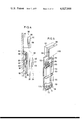
- FIG. 4 is a longitudinal sectional side view showing the locking means for locking the belt-carrying end of the pivot arm and the upper portion of the transfer means in the embodiment of FIG. 1;
- FIG. 5 is a partially cutaway perspective view of the locking means and the transfer means of FIG. 4;
- FIG. 6 is a horizontal sectional view of the locking means of FIG. 4;
- FIG. 7 is a partially cutaway front view of the lower end portion of the transfer means of FIG. 4;
- FIG. 8 is a perspective view of the second embodiment of this invention, showing the same when not in use;
- FIG. 9 is a partially cutaway front view of the belt-carrying end of the pivot arm of the embodiment of FIG. 8;
- FIG. 10 is a perspective view of the third embodiment of this invention, showing the same when not in use;
- FIG. 11 is a partially longitudinally sectional front view of the belt-carrying end of the pivot arm of the embodiment of FIG. 10;
- FIG. 12 is a side view thereof
- FIG. 13 is a partially cutaway front view of the upper portion of the transfer means of the embodiment of FIG. 10;
- FIG. 14 is a horizontal sectional plan view of the lower locking means of the embodiment of FIG. 10 for locking the transfer means of FIG. 13 in its inverted position;
- FIG. 15 is a partially cutaway front view of an alternative of the lowering means of FIG. 13;
- FIG. 16 is a sectional plan view thereof
- FIG. 17 is a perspective view of the fourth embodiment of this invention, showing the same when not in use;
- FIG. 18 is a perspective view of the transfer means incorporated in the pivot arm of the embodiment of FIG. 17;
- FIG. 19 is a partially cutaway front view of the transfer means of FIG. 18, showing the blocks locked;
- FIG. 20 is a longitudinal sectional side view of the lower locking means of the embodiment of FIG. 17.
- FIG. 21 is a perspective view of the fifth embodiment of this invention, showing the same when not in use.
- letter A designates a seat mounted in a car B, said seat being provided with a belt winder 31 at the lower rear portion of one side thereof.
- the belt winder 31 is adapted to house a flexible belt 32 so as to enable it to be drawn therefrom for a required length.
- the belt 32 is secured at its lower end to the belt winder 31.
- the belts 34 and 35 are the two belt sections of one elongated belt folded in two, they may be constituted by two separate belts.
- the belt 32 unwinds itself from the belt winder 31 for such a length as for the belts 34 and 35 to fit the body of the occupant of the seat.
- a pivot arm 36 is pivotally mounted to the roof of the car B over the seat A to its side carrying the belt winder 31 so that it can pivot in a horizontal plane around a pivot 37 from the front-facing position shown in FIG. 1 toward the center pillar C of the car B.
- the pivot 37 for the pivot arm 36 is coupled to a reversible motor 38 mounted on the roof to pivot the pivot arm 36 automatically when a switch suitably disposed in the car is turned on.
- the belts 34 and 35 are connected separately at their upper end to the free end of the pivot arm 36. As shown in FIG. 3, one belt 34 is fixedly attached to the inner side of a projecting portion 39 of the pendent end of the pivot arm 36 through a metal plate 40 and a pin 41. The upper end of the other belt 35 is connected to a metal plate 42 from one side of which an axis 43 projects.
- the projecting axis 43 is provided with one flange 44 at its outer end and another flange 45 halfway of its length so as to divide itself into two axial sections 46 and 47.
- the pendent portion of the pivot arm 36 has an opening 48 formed therein and extending from halfway of its bottom to the lower part of its outer side to receive the metal plate 42 carrying the belt 35, and a notch 49 which connects with the opening 48 and extends upward therefrom to receive the axial section 46 of the axis 43.
- Said means comprises a locking piece 51 slidably mounted in a transverse hole 50 open to the notch 49 halfway thereof.
- a spring 52 biases the locking piece 51 to cause it to project thereinto.
- the locking piece 51 is provided with a pin 54 which projects outward through an elongated transverse slit 53 in the outer side wall of the pendent portion.
- the pin 54 hits a projection suitably disposed to withdraw the locking piece 51 out of the notch 49, thereby unlocking the projecting axis 43.
- the belt 35 is detachably connected at its upper end to the free end of the pivot arm 36.
- a plurality of mounting holes for the pin 41 may be formed in the projecting portion 39 one above another so that the mounting position for the belt 34 can be changed according to the size of the seat occupant.
- the pivot arm 36 As the pivot arm 36 is pivoted toward the center pillar C, it draws the belts 34 and 35 so as to be stretched over the occupant diagonally from his waist to shoulder. Subsequently, only the belt 35 makes it way downward away from the arm 36 to serve as a waist belt. The other belt 34 remains there over the occupant from his waist to shoulder to serve as a shoulder belt.
- the locking means 55 is constituted by a frame member 57 which is secured to the center pillar C and provided with a recess 56 to receive the portion directly above the pendent portion of the arm 36 thus pivoted.
- a locking detent 58 is mounted in one cheek of the frame member 57, biased into the recess 56 by a spring 59.
- the locking detent 58 is tapered so as to be pushed into from the recess 56 to allow the arm 36 to enter it directly above the pendent portion. After the entry thereof, the locking detent 58 projects again into the recess 56 under the bias of the spring 59 to lock the pivot arm 36 therein.
- the locking means 55 further includes a lever 60 for imparting a retracting motion to the locking detent 58, and an electromagnet 61 which attracts the rear end of the lever 60 to retract the locking detent 58 out of the recess 56, thereby releasing the pivot arm 36. (FIG. 6)
- the transfer means 62 To the inner wall of the center pillar C is secured a transfer means 62 which receives the waist belt 35 from the pivot arm 36 and carries it down.
- the transfer means 62 includes a vertically elongated guide member 63 having its upper end directly below the locking means 55 and its lower end disposed adjacent the floor of the car, and a lowering frame 64 mounted in the guide member 63 for vertical movement therein.
- the guide member 63 is fixed substantially vertically to the center pillar C and the side wall of the car directly thereunder as shown in FIG. 1. It is formed to be hollow so as to afford space for vertical movement of the lowering frame 64.
- an elongated opening 65 is formed which consists of a transverse portion located adjacent the top end thereof and open at its front end and which is an elongated longitudinal portion connecting with the transverse portion and extending downward therefrom.
- the elongated opening 65 has a sufficient width for the axial section 47 of the projecting axis 43 to fit loosely therein, and its transverse portion is open at such a height as to receive the axial section 47 therein as the pivot arm 36 is pivoted toward the center pillar C.
- a recess 66 is formed to receive the axial section 47 and a large hole 67 is formed to receive the flange 44 on the projecting axis 43.
- the lowering frame 64 is moved up and down in the guide member 63 by a lowering means 68 incorporated therein.
- the lowering means 68 comprises pulleys 69 rotatably mounted at the top and bottom within the guide member 63, a wire rope 70 passing over the upper and lower pulleys 69 with its ends connected to the top and bottom of the lowering frame 64, and a motor 72 provided at bottom of the guide member 63 and coupled to the lower pulley through a gearing 71.
- the motor 72 imparts upward and downward movement to the lowering frame 64.
- limit switches LS 1 and LS 2 are provided at the top and bottom thereof to detect the upper and lower limits of travel of the lowering frame 64, respectively, and to turn off the motor 72, thereby stopping the frame 64 thereat.
- the recess 66 therein aligns itself with the transverse portion of the elongated opening 65 in the guide member 63 to receive the axial section 47.
- the axial section 47 is located at the crossing between the transverse portion and the longitudinal portion of the elongated opening 65 when the arm 36 is locked by the locking means 55.
- the pin 54 hits said projection to withdraw the locking piece 51 from the notch 49 against the bias of the spring 52, thereby allowing the projecting axis 43 to leave the notch 49 downward.
- the projecting axis 43 is lowered along the elongated opening 65 in the guide member 63.
- the projecting axis 43 is prevented from detachment toward the interior of the car since its outer flange 44 is caught in the large hole 67 in the lowering frame 64.
- the projecting axis 43 carries the waist belt 35 downward into its operative position.
- the transfer means 62 further includes a locking means 73 mounted in the guide member 63 at its bottom for locking the lowering frame 64 in its lowermost position.
- the locking means 73 the operation of which is substantially the same as that of the upper locking means 55, which comprises a locking detent 74, a spring 75, an arm 76, and an electromagnet 77.
- a command to retract the locking detent 74 is given to the electromagnet 77 by operating a seat belt release switch suitably disposed.
- the lowering frame 64 in this embodiment may be replaced by a lowering member provided with a projection which, when the pivot arm 36 is pivoted, fits in a recess formed in the axial section 47 to move the waist belt 35 down.
- the belt-carrying end of the pivot arm 36 points to the front of car B.
- the belts 34 and 35 extend obliquely from the bottom rear of one side of seat A to the free end of the pivot arm 36.
- the seat occupant After adjusting the belt 32 from the belt winder 31 to a suitable length, the seat occupant turns on a start switch (not shown) disposed conveniently. First the motor 38 starts to pivot the arm 36 around the pivot 37 toward the center pillar C. The pivot arm 36 pulls the belts 34 and 35 on an arcuate path so as to be stretched diagonally over the occupant from his waist to shoulder.
- the axial section 47 of the projecting axis 43 fits into the transverse portion of the elongated opening 65 in the guide member 63 and into the recess 66 in the lowering frame 64 with the outer flange 44 received in the large hole 67.
- the locking piece 51 also retracts from the notch 49 to allow the projecting axis 43 to go down.
- the locking of the pivot arm 36 by the locking means 55 is detected by a limit switch (not shown) mounted therein.
- the motor 72 starts to travel the lowering frame 64 downward, guided by the guide member 63.
- the projecting axis 43 will come out of the notch 49 and go down carrying the waist belt 35.
- the limit switch LS 2 operates to stop the motor 72 and the lowering frame 64 gets locked by the locking means 73.
- the shoulder belt 34 remains held adjacent the shoulder of the seat occupant.
- the waist belt 35 thus lowered is secured there so as to bind the waist of the occupant.
- the belts 34 and 35 now hold him securely against the seat A to insure his safety during driving.
- the seat belt assembly is releasable by operating a release switch (not shown). This actuates the electromagnet 77 for the locking means 73 to retract the locking detent 74 and simultaneously energizes the motor 72 to start in the reverse direction.
- the lowering frame 64 will go up carrying the waist belt 35. As the lowering frame 64 approaches its uppermost position, the axial section 46 of the projecting axis 43 forces back into the notch 49 in the pendent portion of the arm 36.
- the electromagnet 61 in the locking means 55 is actuated to retract the locking detent 58 to unlock the pivot arm 36 from the locking means 55.
- the motor 38 is then made to rotate in the reverse direction so that the pivot arm 36 is pivoted back to the original front-facing position, carrying the belts 34 and 35 so as to free the occupant from confinement.
- FIGS. 8 and 9 The second embodiment of this invention shown in FIGS. 8 and 9 will now be described. In this and subsequent embodiments, equivalents to those of the first embodiment will be omitted from the description, but will be given the same reference numbers.
- the second embodiment has a transfer means 62 adapted for use in cars having no center pillar.
- the transfer means 62 comprises a curved tubular guide member 80 secured to the side wall and the floor of the car B, and a lowering arm 81 mounted to be longitudinally movably guided thereby.
- the lowering arm 81 is made of a flexible material, such as synthetic resin to be movable into and out of the curved guide member 80.
- the guide member 80 is formed to be curved arcuately, not sharply, for smooth sliding movement of the lowering arm 81 therein.
- the lowering arm 81 has a rack 82 formed on one edge thereof and is provided with a retaining portion 83 at its top end to receive the projecting axis 43 carrying the waist belt 35 from the pivot arm 36 and retain the same.
- pinions 84 are mounted for engagement with the rack 82 on the lowering arm 81 and a reversible motor (not shown) is provided for driving the pinions 84 to impart longitudinal movement to the lowering arm 81, which receives the waist belt 35 from the pivot arm 36 and carries it down.
- the retaining portion 83 shown in FIG. 9 by an alternate long and short dash line, has a horizontal recess 85 formed therein to be open at its front to receive the axial section 47 of the projecting axis 43. At the innermost position of the recess 85, a magnet 86 is provided which attracts the axial section 47. To the upper and lower walls in the recess 85, flat springs 87 are mounted which normally project into the recess 85 to prevent the axial section 47 from falling out of it, but permit forced entry thereof.
- the guide member 80 is provided with a longitudinal opening 88 extending downward from its top end to allow the axial section 46 of the projecting axis 43 to travel downward beyond the top end of the guide member 80 as the lowering arm 81 goes down.
- the locking means 89 can be constituted by a locking detent, an oscillating arm, an electromagnet, and a spring.
- the waist belt 35 is removably attached to the pivot arm 36 in a different manner.
- a magnet 90 is disposed at the topmost of the notch 49 and flat springs 91 are mounted on its inside walls.
- another guide member (not shown) may be provided which extends upwardly from the upper end of the guide member 80 to direct the motion of the lowering arm 81.
- the motor drives the pinions 84 to move the lowering arm 81 down the guide member 80.
- the projecting axis 43 is forcedly pulled out of the notch 49 in the pivot arm 36.
- the lowering arm 81 goes down the side of the seat A until it reaches its lowermost position.
- the belt 35 now binds the seat occupant across his waist to serve as a waist belt.
- the motor causes the pinion 84 to rotate in the reverse direction to raise the lowering arm 81 carrying the waist belt 35.
- the axial section 46 of the projecting axis 43 is forced into the notch 49 in the pivot arm 36 against the bias of the flat springs 91.
- the waist belt 35 now extends in parallel with the shoulder belt 34.
- a switch (not shown) detects the entry of the projecting axis 43 into the notch 49 to disengage the locking means 55 and cause the motor 38 to rotate in the reverse direction.
- the pivot arm 36 will be unlocked and pivoted to its original front-facing position.
- FIGS. 10-16 The third embodiment of this invention shown in FIGS. 10-16 will be explained below.
- the third embodiment comprises the transfer means 62 adapted for use in cars having no center pillar.
- the transfer means 62 comprises a vertical pivot arm 100 having its lower end pivotally mounted to the side wall of the car.
- the waist belt 35 is removably attached to the end of the pivot arm 36 by inserting the projecting axis 43 from the side, not from under.
- a projecting portion 39 is provided, and the inner side thereof has coupled thereto the shoulder belt 34.
- axes 101 and 102 project coaxially, said axes each having a flange at the end thereof.
- the projecting portion 39 has a recess 103 formed therein to receive the projecting axis 102 with its flange.
- the recess 103 is open on the inner side and the front end when the pivot arm 36 is in its pivoted position.
- a magnet 104 and flat springs 105 are mounted and both performing similarly.
- the pivot 106 around which the vertical arm 100 is pivoted is coupled to a motor (not shown) to pivot the vertical arm 100 forward from the upright position shown in FIG. 10 to the inverted position.
- the motor can be controlled by limit switches (not shown) disposed suitably.
- the vertical arm 100 has at its upper end a retaining portion 83 to receive the waist belt 35 when it is in its upright position with the pivot arm 36 locked by the locking means 55.
- the retaining portion 83 has a horizontal recess 107 on the front end to receive the projecting axis 101 carrying the waist belt 35.
- the retaining portion 83 includes a locking detent 108, a spring 109, an arm 110, and an electromagnet 111.
- the locking detent 108 is tapered to permit entry of the projecting axis 101 into the recess 107.
- the recess 107 is the vertical arm 100 in its upright position is at the same height as the recess 103 in the pivot arm 36 in the pivoted position.
- the waist belt 35 now carried by the vertical arm 100 does not come off during pivotal movement thereof to the inverted position, because the locking detent 108 locks the projecting axis 101.
- a locking means 112 is provided right under the vertical arm 100 to lock the latter in its inverted position.
- the locking means 112 comprises a body 113 having a vertical notch 114 open at the top, bottom and front faces thereof to receive the retaining portion 83 and the metal plate 42, and a horizontal notch 115 to receive the projecting axes 101 and 102.
- Incorporated in the body 113 are a locking detent 116 acting on the retaining portion 83, a spring 117, and an electromagnet 118, and another set of a locking detent 119 and a spring and an electromagnet (not shown) acting on the projecting axis 102.
- These locking detents 116 and 119 perform just as the locking detent 58 for the locking means 55 does.
- FIGS. 15 and 16 show alternative means for locking the projecting axis 101 received by the vertical arm 100.
- a rack lever 120 is longitudinally mounted in the vertical arm 100 at its front portion, the rack lever 120 being biased by a spring 121 to project into the recess 107.
- a pinion 123 is mounted and engages the rack lever 120, and on the other end thereof another pinion 124 is mounted.
- an arm 125 of L-shape section Secured to the upper portion of the side wall of the car is an arm 125 of L-shape section to embrace the upper portion of the vertical arm 100 from behind; the arm 125 has a rack 126 formed on the bottom thereof to engage the pinion 124.
- the rack lever 120 projects into the recess 107 to keep the projecting axis 101 retained.
- the pinion 124 engages the rack 126 to rotate the shaft 122, thus causing the pinion 123 to retract the rack lever 120 out of the recess 107.
- the projecting axis 101 becomes free to go out of the recess 107.
- Said alternative locking means requires no electrically operated devices, thus simplifying the electrical circuit.
- the pivot arm 36 In operating of the third embodiment, when the assembly is not in use, the pivot arm 36 is in its front-facing position and the vertical arm 100 is in its upright position.
- the pivot arm 36 pivots sidewardly until it gets locked in the locking means 55 with the projecting axis 101 fitted in the recess 107 in the retaining portion 83.
- the motor (not shown) is energized to pivot the vertical arm 100 forward around the pivot 106.
- the projecting axis 102 is pulled out of the recess 103 in the pivot arm 36.
- the waist belt 35 is carried on an arcuate path. It moves away from the seated occupant for a while, but thereafter toward him until it comes behind the seat to serve as a waist belt.
- the locking means 112 is disengaged and the vertical arm 100 is pivoted upward to return the waist belt 35 to the pivot arm 36. Then, the pivot arm 36 is pivoted back to the original position.
- This embodiment is characterized in that part of the transfer means 62 is incorporated in the pivot arm 36.
- the latter is formed to be a square tube from at least halfway of its length to the free end thereof to provide a guide channel 130 open at its pendent end.
- a movable lever 131 is mounted in the guide channel 130 for longitudinal movement therein.
- the lever 131 is made of a flexible material such as synthetic resin to flexible to the shape of the pivot arm 36 and be restorable to its original straight form.
- the lever 131 is provided with a rack 132 on one edge thereof.
- the belts 34 and 35 are coupled to the lower end of the lever 131, one above the other.
- the waist belt 35 is connected through a mounting block 134 to a metal plate 133 secured to the lower end of the lever 131.
- the shoulder belt 34 is connected to the lever 131 through a mounting block 136 slidably mounted in an elongated slit 135 longitudinally formed in the lever 131. The distance between the block 134 and the block 136 is freely adjustable.
- a notch 137 is formed in the inner wall of the pivot arm 36 at its end to receive the narrow web portions of the mounting blocks 134 and 136 stacked one upon another when the lever 131 is inserted into the guide channel 130 to the extreme position.
- a driving means 138 for the lever 131 is provided at the top of the center pillar C to lower the lever 131 after the pivot arm 36 has been pivoted.
- the driving means 138 includes a pinion 139 so mounted as to engage the rack 132 on one edge of the lever 131 and a motor (not shown) coupled to the pinion 139.
- the pivot arm 36 has a slit 140 formed in one edge thereof to allow the pinion 139 to mesh with the rack 132 therethrough when it is in its pivoted position.
- the driving means 138 causes the lever 131 to project from and retract into the guide channel 130 when the pivot arm 36 is in its pivoted position.
- a guide member 141 is secured vertically to the side wall of car B directly under the center pillar C.
- the guide member 141 is made in the form of a square tube open at its top end to receive the lever 131 from the pivot arm 36 and guide it downwardly.
- an elongated opening 142 which extends downward from its top end to receive the narrow web portions of the blocks 134 and 136 and permit their passage therealong.
- a locking means 143 for locking the lever 131 in its lowermost position.
- the locking means 143 is incorporated in a box 144, said locking means 143 comprising a detent 146 adapted to project into a through hole 145 in the metal plate 133 upon entry thereof into the box 144, a spring 147, and an electromagnet 148.
- the locking means 143 functions similarly to the locking means in the foregoing embodiments.
- the guide member 141 is provided with stoppers 149 to project on each side of the elongated opening 142.
- the mounting block 136 carrying the shoulder belt 34 hits the stoppers 149 and is hindered from further lowering. It will be seen from FIG. 18 that the block 136 carrying the shoulder belt 34 has a wider head 150 than the head 151 of the block 134 carrying the waist belt 35.
- the distance between the stoppers 149 is such as to permit passage of the block 134, but not that of the block 136.
- This arrangement ensures that as the lever 131 goes down, the belt 34 stops at the upper portion of the guide member 141 to serve as a shoulder belt.
- the vertical position of the stoppers 149 can be adjusted according to the size of the seat occupant.
- the lever 131 continues to go down carrying the waist belt 35.
- the lever 131 is locked by the locking means 143, and the waist belt 35 is stretched across the waist of the occupant.
- the block 136 is now held between the upper edge of the elongated slit 135 and the stoppers 149.
- the lever 131 is of a sufficient length for its upper end to be still in the pivot arm 36 and to have the rack 132 in engagement with the pinion 139 even with the lever 131 locked.
- the shoulder belt 34 is hindered by the stoppers 149 from further lowering to serve as a shoulder belt, while the waist belt 35 goes on lowering past the stoppers 149 until it reaches its lowermost position to serve as a waist belt.
- This embodiment is characterized in that the pendent portion of the pivot arm 36 further extends downward.
- the waist belt is connected to the lower end of the extension at a distance from the shoulder belt, unlike the foregoing embodiments in which these two belts are connected side by side.
- a turnable connector 152 Disposed below the mounting position for the shoulder belt are a turnable connector 152 and a spring-loaded telescopic member 153 extensible downwardly.
- the telescopic member 153 is contracted under the pull of a spring (not shown) unless it is pulled downward.
- the connector 152 is turnable toward the seat to avoid collision of the pendent portion against the handle of the car during the pivotal movement of the pivot arm 36.
- a metal plate 155 which is received in a locking means 154 under the center pillar and locked by a detent (not shown) thereof to retain the waist belt.
- the seat occupant pivots the pivot arm 36 toward the center pillar, holding it on a projection 158 provided for easy handling.
- the pivot arm 36 gets locked by an upper locking means 156.
- the pendent portion is then manually pulled down against the pull of the spring into confinement by the lower locking means 154.
- the shoulder and waist belts are now in their operative position to the seat occupant.
Landscapes
- Engineering & Computer Science (AREA)
- Mechanical Engineering (AREA)
- Automotive Seat Belt Assembly (AREA)
Applications Claiming Priority (5)
| Application Number | Priority Date | Filing Date | Title |
|---|---|---|---|
| JP4269675U JPS5445613Y2 (it) | 1975-03-27 | 1975-03-27 | |
| JP4269575U JPS5445612Y2 (it) | 1975-03-27 | 1975-03-27 | |
| JA50-42696[U]JA | 1975-03-27 | ||
| JA50-42695[U] | 1975-03-27 | ||
| JP4269775U JPS5445614Y2 (it) | 1975-03-27 | 1975-03-27 |
Publications (1)
| Publication Number | Publication Date |
|---|---|
| US4027900A true US4027900A (en) | 1977-06-07 |
Family
ID=27291316
Family Applications (1)
| Application Number | Title | Priority Date | Filing Date |
|---|---|---|---|
| US05/594,432 Expired - Lifetime US4027900A (en) | 1975-03-27 | 1975-07-09 | Seat belt assembly |
Country Status (6)
| Country | Link |
|---|---|
| US (1) | US4027900A (it) |
| AU (1) | AU8281675A (it) |
| DE (1) | DE2533392A1 (it) |
| FR (1) | FR2305201A1 (it) |
| GB (1) | GB1477259A (it) |
| IT (1) | IT1036940B (it) |
Cited By (5)
| Publication number | Priority date | Publication date | Assignee | Title |
|---|---|---|---|---|
| US4290629A (en) * | 1978-08-18 | 1981-09-22 | Nippon Seiko Kabushiki Kaisha | Seat belt emergency locking device |
| US4549749A (en) * | 1983-09-28 | 1985-10-29 | Allied Corporation | Pillar integrated web guide |
| US5183291A (en) * | 1991-03-13 | 1993-02-02 | Shah Mrugesh K | Automatic seat and shoulder belt apparatus |
| CN107539184A (zh) * | 2017-11-04 | 2018-01-05 | 佛山月转科技有限公司 | 一种公交车腿部站稳辅助装置 |
| CN113246903A (zh) * | 2021-06-30 | 2021-08-13 | 长沙理工大学 | 一种汽车安全带自动系扣和释放系统及方法 |
Families Citing this family (2)
| Publication number | Priority date | Publication date | Assignee | Title |
|---|---|---|---|---|
| US4502710A (en) * | 1978-06-08 | 1985-03-05 | Takata Kogyo Co., Ltd. | Lockable moving belt anchor for passive vehicle occupant restraint belt systems |
| DE202021002772U1 (de) * | 2021-08-26 | 2022-12-16 | Hsm Gmbh & Co. Kg | Kraftfahrzeug mit mindestens einem Fahrersitz |
Citations (3)
| Publication number | Priority date | Publication date | Assignee | Title |
|---|---|---|---|---|
| US3830518A (en) * | 1972-01-24 | 1974-08-20 | T Silber | Seat belt actuating means |
| US3895824A (en) * | 1973-02-23 | 1975-07-22 | Volkswagenwerk Ag | Passive actuating device for a safety belt |
| US3900078A (en) * | 1972-03-22 | 1975-08-19 | Nissan Motor | Safety harness arrangement |
Family Cites Families (1)
| Publication number | Priority date | Publication date | Assignee | Title |
|---|---|---|---|---|
| JPS5028425U (it) * | 1973-07-11 | 1975-04-01 |
-
1975
- 1975-07-08 AU AU82816/75A patent/AU8281675A/en not_active Expired
- 1975-07-09 GB GB2896275A patent/GB1477259A/en not_active Expired
- 1975-07-09 US US05/594,432 patent/US4027900A/en not_active Expired - Lifetime
- 1975-07-22 IT IT7550618A patent/IT1036940B/it active
- 1975-07-25 DE DE19752533392 patent/DE2533392A1/de active Pending
- 1975-07-29 FR FR7523576A patent/FR2305201A1/fr active Granted
Patent Citations (3)
| Publication number | Priority date | Publication date | Assignee | Title |
|---|---|---|---|---|
| US3830518A (en) * | 1972-01-24 | 1974-08-20 | T Silber | Seat belt actuating means |
| US3900078A (en) * | 1972-03-22 | 1975-08-19 | Nissan Motor | Safety harness arrangement |
| US3895824A (en) * | 1973-02-23 | 1975-07-22 | Volkswagenwerk Ag | Passive actuating device for a safety belt |
Cited By (5)
| Publication number | Priority date | Publication date | Assignee | Title |
|---|---|---|---|---|
| US4290629A (en) * | 1978-08-18 | 1981-09-22 | Nippon Seiko Kabushiki Kaisha | Seat belt emergency locking device |
| US4549749A (en) * | 1983-09-28 | 1985-10-29 | Allied Corporation | Pillar integrated web guide |
| US5183291A (en) * | 1991-03-13 | 1993-02-02 | Shah Mrugesh K | Automatic seat and shoulder belt apparatus |
| CN107539184A (zh) * | 2017-11-04 | 2018-01-05 | 佛山月转科技有限公司 | 一种公交车腿部站稳辅助装置 |
| CN113246903A (zh) * | 2021-06-30 | 2021-08-13 | 长沙理工大学 | 一种汽车安全带自动系扣和释放系统及方法 |
Also Published As
| Publication number | Publication date |
|---|---|
| FR2305201A1 (fr) | 1976-10-22 |
| FR2305201B1 (it) | 1977-12-09 |
| GB1477259A (en) | 1977-06-22 |
| IT1036940B (it) | 1979-10-30 |
| DE2533392A1 (de) | 1976-10-07 |
| AU8281675A (en) | 1977-01-13 |
Similar Documents
| Publication | Publication Date | Title |
|---|---|---|
| US3833239A (en) | Seat belt | |
| US6267409B1 (en) | Vehicle restraint presenting system | |
| US4027900A (en) | Seat belt assembly | |
| US20010040369A1 (en) | Restraint belt presenter with rising arm and offset rotary action | |
| EP0002885B1 (en) | Passive lap and shoulder belt system | |
| US5538283A (en) | Automobile armrest apparatus for presenting restaint system | |
| US5505491A (en) | Automobile armrest apparatus for presenting restraint system | |
| US11279266B2 (en) | Motor home chair lift | |
| JPS606370Y2 (ja) | ウエビングスライダロツク装置 | |
| JPS5918925Y2 (ja) | 移動アンカ−式パツシブベルト装置 | |
| US4274658A (en) | Vehicle occupant restraint system | |
| US4256330A (en) | Passive seat belt system | |
| US4201401A (en) | Passive lap and shoulder belt system | |
| US3927902A (en) | Safety belt arrangement for individuals | |
| US3977696A (en) | Seat belt equipment | |
| US5190315A (en) | Passive safety belt system | |
| US4211430A (en) | Passive lap and shoulder belt system | |
| US4218075A (en) | Passive seat belt system having lap belt lifter | |
| KR910000933B1 (ko) | 차량의 시이트벨트장치 | |
| US4218076A (en) | Passive seat belt system | |
| US3881745A (en) | Vehicle occupant restraint device | |
| US4186942A (en) | Passive shoulder belt | |
| US4165100A (en) | Safety belt applying system | |
| US4203618A (en) | Passive occupant restraint system | |
| JPS6312021B2 (it) |