US4006260A - Method and apparatus for evaporation of moisture from fruit and vegetable particles - Google Patents
Method and apparatus for evaporation of moisture from fruit and vegetable particles Download PDFInfo
- Publication number
- US4006260A US4006260A US05/544,959 US54495975A US4006260A US 4006260 A US4006260 A US 4006260A US 54495975 A US54495975 A US 54495975A US 4006260 A US4006260 A US 4006260A
- Authority
- US
- United States
- Prior art keywords
- particles
- pressure
- oil
- temperature
- torr
- Prior art date
- Legal status (The legal status is an assumption and is not a legal conclusion. Google has not performed a legal analysis and makes no representation as to the accuracy of the status listed.)
- Expired - Lifetime
Links
- 239000002245 particle Substances 0.000 title claims abstract description 326
- 238000000034 method Methods 0.000 title claims abstract description 94
- 238000001704 evaporation Methods 0.000 title claims abstract description 27
- 235000012055 fruits and vegetables Nutrition 0.000 title abstract description 18
- 230000008020 evaporation Effects 0.000 title description 21
- 230000018044 dehydration Effects 0.000 claims abstract description 59
- 238000006297 dehydration reaction Methods 0.000 claims abstract description 59
- 235000013305 food Nutrition 0.000 claims abstract description 58
- 230000001965 increasing effect Effects 0.000 claims abstract description 6
- 230000003247 decreasing effect Effects 0.000 claims abstract description 3
- XLYOFNOQVPJJNP-UHFFFAOYSA-N water Chemical compound O XLYOFNOQVPJJNP-UHFFFAOYSA-N 0.000 claims description 128
- 239000007788 liquid Substances 0.000 claims description 87
- 230000008569 process Effects 0.000 claims description 67
- 238000007667 floating Methods 0.000 claims description 40
- 230000033001 locomotion Effects 0.000 claims description 25
- 238000012545 processing Methods 0.000 claims description 25
- 239000007921 spray Substances 0.000 claims description 23
- 238000001816 cooling Methods 0.000 claims description 20
- 230000002829 reductive effect Effects 0.000 claims description 20
- 238000004891 communication Methods 0.000 claims description 12
- 230000001007 puffing effect Effects 0.000 claims description 9
- 238000004806 packaging method and process Methods 0.000 claims description 6
- 238000007599 discharging Methods 0.000 claims description 5
- 230000008093 supporting effect Effects 0.000 claims description 3
- 238000010924 continuous production Methods 0.000 claims 1
- 230000003028 elevating effect Effects 0.000 claims 1
- 208000005156 Dehydration Diseases 0.000 abstract description 51
- 238000004519 manufacturing process Methods 0.000 abstract description 22
- 239000003921 oil Substances 0.000 description 303
- 235000019198 oils Nutrition 0.000 description 302
- 235000013399 edible fruits Nutrition 0.000 description 82
- 238000012546 transfer Methods 0.000 description 43
- 239000000047 product Substances 0.000 description 38
- 206010019233 Headaches Diseases 0.000 description 30
- 235000007119 Ananas comosus Nutrition 0.000 description 18
- 230000009471 action Effects 0.000 description 18
- 235000011430 Malus pumila Nutrition 0.000 description 16
- 235000015103 Malus silvestris Nutrition 0.000 description 16
- 241000220225 Malus Species 0.000 description 13
- 239000011148 porous material Substances 0.000 description 13
- 244000291473 Musa acuminata Species 0.000 description 12
- 235000021022 fresh fruits Nutrition 0.000 description 12
- 230000001105 regulatory effect Effects 0.000 description 12
- 238000001035 drying Methods 0.000 description 11
- 244000099147 Ananas comosus Species 0.000 description 10
- 239000012530 fluid Substances 0.000 description 10
- 241000234282 Allium Species 0.000 description 9
- 235000002732 Allium cepa var. cepa Nutrition 0.000 description 9
- 230000002706 hydrostatic effect Effects 0.000 description 9
- 239000000203 mixture Substances 0.000 description 9
- 235000015112 vegetable and seed oil Nutrition 0.000 description 9
- 239000008158 vegetable oil Substances 0.000 description 9
- 241000234671 Ananas Species 0.000 description 8
- 241000219094 Vitaceae Species 0.000 description 8
- 235000021452 apple slice Nutrition 0.000 description 8
- 230000008901 benefit Effects 0.000 description 8
- 239000000796 flavoring agent Substances 0.000 description 8
- 235000019634 flavors Nutrition 0.000 description 8
- 235000021021 grapes Nutrition 0.000 description 8
- 230000004048 modification Effects 0.000 description 8
- 238000012986 modification Methods 0.000 description 8
- 238000003860 storage Methods 0.000 description 8
- 235000018290 Musa x paradisiaca Nutrition 0.000 description 7
- 239000006227 byproduct Substances 0.000 description 7
- 238000005188 flotation Methods 0.000 description 7
- 235000013311 vegetables Nutrition 0.000 description 7
- RAHZWNYVWXNFOC-UHFFFAOYSA-N Sulphur dioxide Chemical compound O=S=O RAHZWNYVWXNFOC-UHFFFAOYSA-N 0.000 description 6
- 238000002360 preparation method Methods 0.000 description 6
- 230000003068 static effect Effects 0.000 description 6
- 238000009834 vaporization Methods 0.000 description 6
- 230000008016 vaporization Effects 0.000 description 6
- 244000060011 Cocos nucifera Species 0.000 description 5
- 235000013162 Cocos nucifera Nutrition 0.000 description 5
- 244000081841 Malus domestica Species 0.000 description 5
- 238000009833 condensation Methods 0.000 description 5
- 230000005494 condensation Effects 0.000 description 5
- 238000011161 development Methods 0.000 description 5
- 239000000463 material Substances 0.000 description 5
- 230000007246 mechanism Effects 0.000 description 5
- QSHDDOUJBYECFT-UHFFFAOYSA-N mercury Chemical compound [Hg] QSHDDOUJBYECFT-UHFFFAOYSA-N 0.000 description 5
- 229910052753 mercury Inorganic materials 0.000 description 5
- 230000032258 transport Effects 0.000 description 5
- 229910000831 Steel Inorganic materials 0.000 description 4
- 235000021015 bananas Nutrition 0.000 description 4
- 230000006835 compression Effects 0.000 description 4
- 238000007906 compression Methods 0.000 description 4
- 239000000498 cooling water Substances 0.000 description 4
- 238000013461 design Methods 0.000 description 4
- 239000007789 gas Substances 0.000 description 4
- 238000010438 heat treatment Methods 0.000 description 4
- 230000006872 improvement Effects 0.000 description 4
- 239000003507 refrigerant Substances 0.000 description 4
- 239000007787 solid Substances 0.000 description 4
- 239000010959 steel Substances 0.000 description 4
- 235000000346 sugar Nutrition 0.000 description 4
- 150000008163 sugars Chemical class 0.000 description 4
- 244000000626 Daucus carota Species 0.000 description 3
- 235000002767 Daucus carota Nutrition 0.000 description 3
- 240000004713 Pisum sativum Species 0.000 description 3
- 235000010582 Pisum sativum Nutrition 0.000 description 3
- 244000018633 Prunus armeniaca Species 0.000 description 3
- 235000009827 Prunus armeniaca Nutrition 0.000 description 3
- 240000006365 Vitis vinifera Species 0.000 description 3
- 235000014787 Vitis vinifera Nutrition 0.000 description 3
- 239000012267 brine Substances 0.000 description 3
- 238000010276 construction Methods 0.000 description 3
- 230000000694 effects Effects 0.000 description 3
- 239000013529 heat transfer fluid Substances 0.000 description 3
- 238000011068 loading method Methods 0.000 description 3
- 238000005192 partition Methods 0.000 description 3
- 238000004321 preservation Methods 0.000 description 3
- 238000005057 refrigeration Methods 0.000 description 3
- HPALAKNZSZLMCH-UHFFFAOYSA-M sodium;chloride;hydrate Chemical compound O.[Na+].[Cl-] HPALAKNZSZLMCH-UHFFFAOYSA-M 0.000 description 3
- 150000003464 sulfur compounds Chemical class 0.000 description 3
- 206010000060 Abdominal distension Diseases 0.000 description 2
- IJGRMHOSHXDMSA-UHFFFAOYSA-N Atomic nitrogen Chemical compound N#N IJGRMHOSHXDMSA-UHFFFAOYSA-N 0.000 description 2
- 241000287828 Gallus gallus Species 0.000 description 2
- 241000293001 Oxytropis besseyi Species 0.000 description 2
- 244000061456 Solanum tuberosum Species 0.000 description 2
- 235000002595 Solanum tuberosum Nutrition 0.000 description 2
- 235000021016 apples Nutrition 0.000 description 2
- 238000009835 boiling Methods 0.000 description 2
- 238000004140 cleaning Methods 0.000 description 2
- 125000004122 cyclic group Chemical group 0.000 description 2
- 230000001419 dependent effect Effects 0.000 description 2
- 238000010586 diagram Methods 0.000 description 2
- 239000000428 dust Substances 0.000 description 2
- 239000008157 edible vegetable oil Substances 0.000 description 2
- 230000008030 elimination Effects 0.000 description 2
- 238000003379 elimination reaction Methods 0.000 description 2
- 238000007710 freezing Methods 0.000 description 2
- 230000008014 freezing Effects 0.000 description 2
- 235000013569 fruit product Nutrition 0.000 description 2
- 239000000446 fuel Substances 0.000 description 2
- 230000005484 gravity Effects 0.000 description 2
- 230000001976 improved effect Effects 0.000 description 2
- 230000000977 initiatory effect Effects 0.000 description 2
- 238000007689 inspection Methods 0.000 description 2
- 230000002045 lasting effect Effects 0.000 description 2
- 238000012423 maintenance Methods 0.000 description 2
- 235000013372 meat Nutrition 0.000 description 2
- 229910052751 metal Inorganic materials 0.000 description 2
- 239000002184 metal Substances 0.000 description 2
- 229910052698 phosphorus Inorganic materials 0.000 description 2
- 235000012015 potatoes Nutrition 0.000 description 2
- 239000003755 preservative agent Substances 0.000 description 2
- 230000002335 preservative effect Effects 0.000 description 2
- 230000002035 prolonged effect Effects 0.000 description 2
- 230000000717 retained effect Effects 0.000 description 2
- 230000002441 reversible effect Effects 0.000 description 2
- 229920006395 saturated elastomer Polymers 0.000 description 2
- 238000007789 sealing Methods 0.000 description 2
- 238000000926 separation method Methods 0.000 description 2
- 238000004513 sizing Methods 0.000 description 2
- 239000000126 substance Substances 0.000 description 2
- 229910052717 sulfur Inorganic materials 0.000 description 2
- 239000011593 sulfur Substances 0.000 description 2
- 235000012431 wafers Nutrition 0.000 description 2
- 206010063659 Aversion Diseases 0.000 description 1
- 241000167854 Bourreria succulenta Species 0.000 description 1
- 241000238557 Decapoda Species 0.000 description 1
- 241000196324 Embryophyta Species 0.000 description 1
- 240000005561 Musa balbisiana Species 0.000 description 1
- 239000006057 Non-nutritive feed additive Substances 0.000 description 1
- 244000141353 Prunus domestica Species 0.000 description 1
- 235000014443 Pyrus communis Nutrition 0.000 description 1
- NINIDFKCEFEMDL-UHFFFAOYSA-N Sulfur Chemical compound [S] NINIDFKCEFEMDL-UHFFFAOYSA-N 0.000 description 1
- 235000009754 Vitis X bourquina Nutrition 0.000 description 1
- 235000012333 Vitis X labruscana Nutrition 0.000 description 1
- 238000010521 absorption reaction Methods 0.000 description 1
- 238000009825 accumulation Methods 0.000 description 1
- 238000010923 batch production Methods 0.000 description 1
- 230000033228 biological regulation Effects 0.000 description 1
- 238000009924 canning Methods 0.000 description 1
- 235000019693 cherries Nutrition 0.000 description 1
- 239000003086 colorant Substances 0.000 description 1
- 239000012141 concentrate Substances 0.000 description 1
- 235000009508 confectionery Nutrition 0.000 description 1
- 239000000356 contaminant Substances 0.000 description 1
- 238000010411 cooking Methods 0.000 description 1
- 238000005520 cutting process Methods 0.000 description 1
- 238000009792 diffusion process Methods 0.000 description 1
- 238000006073 displacement reaction Methods 0.000 description 1
- 235000011869 dried fruits Nutrition 0.000 description 1
- 229920001971 elastomer Polymers 0.000 description 1
- 238000005265 energy consumption Methods 0.000 description 1
- 229940014425 exodus Drugs 0.000 description 1
- 239000003925 fat Substances 0.000 description 1
- 230000002349 favourable effect Effects 0.000 description 1
- 238000011049 filling Methods 0.000 description 1
- 239000000295 fuel oil Substances 0.000 description 1
- 230000003760 hair shine Effects 0.000 description 1
- 238000003306 harvesting Methods 0.000 description 1
- 238000007654 immersion Methods 0.000 description 1
- 239000012535 impurity Substances 0.000 description 1
- 230000001939 inductive effect Effects 0.000 description 1
- 239000004615 ingredient Substances 0.000 description 1
- 230000002401 inhibitory effect Effects 0.000 description 1
- 238000002347 injection Methods 0.000 description 1
- 239000007924 injection Substances 0.000 description 1
- 238000003780 insertion Methods 0.000 description 1
- 230000037431 insertion Effects 0.000 description 1
- 238000009434 installation Methods 0.000 description 1
- 230000002452 interceptive effect Effects 0.000 description 1
- 230000014759 maintenance of location Effects 0.000 description 1
- 230000002503 metabolic effect Effects 0.000 description 1
- 238000012544 monitoring process Methods 0.000 description 1
- 229910052757 nitrogen Inorganic materials 0.000 description 1
- 235000014593 oils and fats Nutrition 0.000 description 1
- 235000021453 onion ring Nutrition 0.000 description 1
- 239000010461 other edible oil Substances 0.000 description 1
- 238000013021 overheating Methods 0.000 description 1
- 238000012856 packing Methods 0.000 description 1
- 235000019629 palatability Nutrition 0.000 description 1
- 230000036961 partial effect Effects 0.000 description 1
- 230000000063 preceeding effect Effects 0.000 description 1
- 238000003825 pressing Methods 0.000 description 1
- 230000000135 prohibitive effect Effects 0.000 description 1
- 235000012437 puffed product Nutrition 0.000 description 1
- 230000005855 radiation Effects 0.000 description 1
- 239000002994 raw material Substances 0.000 description 1
- 230000000630 rising effect Effects 0.000 description 1
- 239000000243 solution Substances 0.000 description 1
- 238000005507 spraying Methods 0.000 description 1
- 230000000087 stabilizing effect Effects 0.000 description 1
- 230000001954 sterilising effect Effects 0.000 description 1
- 238000000859 sublimation Methods 0.000 description 1
- 230000008022 sublimation Effects 0.000 description 1
- LSNNMFCWUKXFEE-UHFFFAOYSA-L sulfite Chemical class [O-]S([O-])=O LSNNMFCWUKXFEE-UHFFFAOYSA-L 0.000 description 1
- 239000000725 suspension Substances 0.000 description 1
- 230000002459 sustained effect Effects 0.000 description 1
- 230000009897 systematic effect Effects 0.000 description 1
- 231100000816 toxic dose Toxicity 0.000 description 1
- 238000009966 trimming Methods 0.000 description 1
- 230000036967 uncompetitive effect Effects 0.000 description 1
- 210000001364 upper extremity Anatomy 0.000 description 1
- 238000009489 vacuum treatment Methods 0.000 description 1
- 235000019871 vegetable fat Nutrition 0.000 description 1
- 239000002699 waste material Substances 0.000 description 1
- 238000005303 weighing Methods 0.000 description 1
Images


Classifications
-
- F—MECHANICAL ENGINEERING; LIGHTING; HEATING; WEAPONS; BLASTING
- F26—DRYING
- F26B—DRYING SOLID MATERIALS OR OBJECTS BY REMOVING LIQUID THEREFROM
- F26B7/00—Drying solid materials or objects by processes using a combination of processes not covered by a single one of groups F26B3/00 and F26B5/00
-
- A—HUMAN NECESSITIES
- A23—FOODS OR FOODSTUFFS; TREATMENT THEREOF, NOT COVERED BY OTHER CLASSES
- A23B—PRESERVATION OF FOODS, FOODSTUFFS OR NON-ALCOHOLIC BEVERAGES; CHEMICAL RIPENING OF FRUIT OR VEGETABLES
- A23B7/00—Preservation of fruit or vegetables; Chemical ripening of fruit or vegetables
- A23B7/02—Dehydrating; Subsequent reconstitution
-
- A—HUMAN NECESSITIES
- A23—FOODS OR FOODSTUFFS; TREATMENT THEREOF, NOT COVERED BY OTHER CLASSES
- A23P—SHAPING OR WORKING OF FOODSTUFFS, NOT FULLY COVERED BY A SINGLE OTHER SUBCLASS
- A23P30/00—Shaping or working of foodstuffs characterised by the process or apparatus
- A23P30/30—Puffing or expanding
- A23P30/32—Puffing or expanding by pressure release, e.g. explosion puffing; by vacuum treatment
Definitions
- the present invention relates to the preservation of fruit and vegetable particles and pertains particularly to such preservation by dehydration.
- Curves 30-31 show the time of exposure to the weather for traditional methods whereby the particles are laid out in the sun on trays to dry for four or more days, during which time they also collect dust and are usually darkened by the sun's ultraviolet rays.
- the moisture content is reduced by evaporation from the initial value of about 80% to the range of 25% to 15%.
- Some consumers also found the caramelized quality of fruit sugars that was generated to a small extent in some products to be objectionable, and this caramelization was found to be due to prolonged overheating in the hot sun.
- Enclosed kilns were developed that blew heated dry air at about 65° C. over the fruit on trays, and between particles laid out on a perforated kiln floor.
- the particles were treated to heavy doses of sulfur dioxide, and also sometimes were dipped in solutions of sulfites and other chemical preservative. The result was an attractive product for eye-appeal, but many people who ate these products developed an aversion to the taste of the sulfur compounds that were associated with the food.
- Flavor is all-important, and the secret of success in fruit and vegetable marketing is to provide a product that has fully matured before harvesting, and preserve that flavorful product at low cost, and transport it in large quantities to sell at low unit profit on the mass markets.
- the fruit was discharged with a substantial film of oil clinging thereto, which was objectionable. Also, the process required hand labor for filling and emptying trays of fruit and for the skilled manipulation of the many valves regulating the process events. Heat for the process came as steam from a high pressure boiler which burned furnace oil or the like.
- Another object of the present invention is to provide automatic apparatus for the manufacture of low-moisture puffed fruit particles from fresh fruit particles.
- Another object of the present invention is to provide method and apparatus for utilizing solar energy for the rapid evaporation of the major portion of the natural moisture of fresh fruit particles without causing caramelization of the sugars of the fruit, and without darkening the natural color of the fruit particles, and without the addition of an artificial preservative or other contaminants or adulterants.
- Another object is to provide an efficient heat transfer chain to transfer heat at comparatively low temperature from a heated water layer to an oil layer so as to simultaneously heat and purify the oil, making the heated oil suitable for contacting fruit and other comestibles without imparting undesirable flavors to the comestible.
- Another object is to provide an efficient method for utilizing heat at relatively low temperature, in a liquid heat transfer medium, to dehydrate and puff thin, large-diameter slices of ripe fruit, in zones of controlled subatmospheric pressure.
- Another object is to provide a means for support of delicate slices and transport through stages of decreasing pressure and increasing temperature without materially damaging the slices.
- Another object is to provide an efficient method for utilizing heat at relatively low temperature, for dehydration, such as solar energy from hot water in a solar water heater, thence to the surfaces of food particles in a series of vacuum dehydration stages.
- Another object is to provide method and apparatus for contacting a procession of food particles at subatmospheric pressure with liquid heat transfer medium at progressively higher temperatures.
- Another object is to provide means for removing water vapor at progressively lower absolute pressures from the procession of food particles which is being dehydrated at subatmospheric pressures.
- Another object is to provide a system for efficiently maintaining zones or stations of varied subatmospheric pressure of water vapor, in the presence of a liquid heat transfer medium, and advancing a procession of food particles through such zones so that the particles are subjected to progressively lower absolute pressure and increasing temperature of the liquid medium, as they advance from an entrance point to an exit point.
- Another object of the present invention is to provide apparatus for the automatic production of a procession of low-moisture puffed fruit particles containing edible oil in the pores thereof.
- Another object is to provide method and apparatus for elimination of free oil from the surfaces of the puffed particles, while preserving the puffed structure.
- a further object is to provide a method for evaporating the major portion of the natural moisture of fruit particles under conditions of subatmospheric pressure such that the moisture vapor may be condensed on surfaces that are maintained at temperatures close to the temperature of the ambient atmosphere.
- a further object is to provide a method for evaporating the major portion of the moisture of fruit particles in a thermodynamic system that utilizes a liquid heat transfer medium and low-cost heat sources at temperatures below the boiling point of water at normal atmospheric pressure.
- a vegetable oil is heated and purified by contact with a layer of heated water or by other suitable means, such as a surface heat exchanger, and a centrifugal oil purifier, and is injected into a region of subatmospheric pressure to contact food particles to be dehydrated.
- the particles and the oil are conveyed together in a multi-stage process through regions of progressively higher temperature below the caramelization temperature of the fruit sugars or other heat-sensitive component of the particles for the duration of the process, and the pressure of the successive regions is progressively reduced in stages to about 3 torr, until substantially all the moisture of the fruit has evaporated, and has been condensed in a condenser cooled by prevailing natural means.
- the hot, puffed food particles containing about 2% moisture, are cooled by immersion in oil that has been cooled by ambient means, the oil is then removed from contact with the surfaces of the particles, and the particles are removed from the low-pressure environment into normal atmosphere without disturbing portions of the product that had been introduced into earlier stages of the process and are now undergoing simultaneous processing in the vacuum regions.
- the present invention utilizes a multiple pressure subatmospheric vacuum system for condensing water vapor from a continuous vacuum dehydrator that treats a procession of food particles to evaporation by a liquid heat transfer medium in contact with the particles.
- the major component of the moisture of the particles is evaporated at a relatively low temperature of the heat transfer medium, and at a relatively high subatmospheric pressure.
- a minor proportion of the moisture is evaporated at a relatively higher temperature of the heat transfer medium, and at a relatively low subatmospheric pressure.
- the separate vapor streams are absorbed in separate divisions of the vacuum system that operate at maximum efficiency within the range of pressures of the vapor streams with which they are respectively connected.
- “Fruit” is used in this specification to include also “vegetable”, and “particle” is used to designate a cut piece of fruit or vegetable of a size suitable for processing by the method described, and may also designate whole grapes and other small whole fruit or vegetable, which is processed without cutting. The process is also applicable to piece-meat such as shrimp, chicken, etc. "Macropore” is an enlarged cavity inside the particle produced by expansion of vapor therein.
- “Case-hardening” is the condition that is produced on the surfaces of some particles such as slices or dices of apple, wherein the surface of the particle has been quickly dried in the process to be described, and offers resistence to the escape of water vapors from the interior of the particle, resulting in the build-up of a substantial difference in pressure between the inside vapor pressure and the hydrostatic pressure of the oil in which the particle is immersed. Case-hardening can result in the generation of macropores. "Puffing” is the retention of almost the original size and shape of a piece of fruit through the generation of numerous empty pores and macropores inside the particle, giving the finished low-moisture particle a crisp, tender texture.
- Low moisture is a moisture content such that the particle is crisp and stays puffed when brought out into normal atmospheric pressure.
- Low-moisture puffed fruits contain from about 2% to 5% water.
- Oil designates an edible vegetable oil or fat used herein as a liquid heat transfer medium, and as an ingredient of the puffed, low-moisture fruit products produced by the present invention.
- Thin slices such as of apple or pineapple of about one millimeter thickness, may contain as much as 20% to 40% of oil in their case-hardened skin pores.
- Thicker slices of the same fruit or other particles of three to five millimeters thickness will contain only about 15% to 5% oil, which generally does not penetrate far into the interior of the puffed particle. Such oil, when limited, is helpful to improve palatability.
- FIG. 1 is a graph containing curves that compare the conditions of pressure and the duration of exposure to heat used in the prior art, with pressures and duration of the present invention
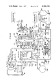
- FIG. 2 is a schematic layout of a processing system in accordance with the present invention for carrying out the process of the present invention
- FIG. 3 is a graphical representation of processing conditions for floating fruit particles in accordance with the present invention, relating vapor head pressures to moisture content, moisture evaporated, and duration of treatment in contact with the heated oil, and oil temperatures, for two examples of particle size.
- FIG. 4 is a schematic layout of an alternate embodiment of a system in accordance with the present invention.
- FIG. 5 is an exploded schematic diagram showing the preferred embodiment of control means for the control of automation of the process and apparatus of FIG. 4;
- FIG. 6 is a longitudinal sectional fragmented view of a hydraulic rotary valve device utilized to energize and time the automatic operation of the process and apparatus of the invention
- FIG. 7 is an end view of the valve of FIG. 6.
- FIG. 8 is a plan view of the preferred form of the processing vessel of FIG. 15, with dome removed;
- FIGS. 9-12 are schematic illustrations of the stages of operation of the discharge station and adjacent stations of the system of FIG. 5;
- FIG. 13 is a plan view of a valve element 43 of the preferred form of valve 42 in FIG. 15;
- FIG. 14 is a view of the valve element of FIG. 13 taken on the section line 14--14 of FIG. 15;
- FIG. 15 is an elevational view in section of the preferred form of the vacuum dehydrating apparatus taken generally along line 15--15 of FIG. 8;
- FIG. 16 is an exploded detailed view, partially in section, of the operating mechanism of the intermediate screen of the apparatus of FIG. 15;
- FIG. 17 is a plan view in section of the apparatus taken generally along line 17--17 of FIG. 15;
- FIG. 18 is a plan view of the portion of the apparatus taken on the section line 18--18 of FIG. 15, with a portion broken away;
- FIG. 19 is a fragmentary view partially in section, of the inflatable seal of the discharge station of the apparatus of FIG. 15;
- FIG. 20 is a longitudinal sectional view of the actuating motor of FIG. 18;
- FIG. 21 is a plan view of the apparatus of FIG. 15, taken generally along line 21--21 showing an alternate construction for the discharge shutter 189;
- FIG. 22 is a fragmentary sectional view of the shutter mechanism of discharge station h, taken generally along line 22--22 of FIG. 21;
- FIG. 23 is a fragmentary sectional view, taken generally along line 23--23 of FIG. 21, of the discharge station h;
- FIG. 24 is a schematic representation of another embodiment of the apparatus for carrying out the present invention on floating particles
- FIG. 25 is a graphical representation of ranges of pressure and temperature under which the process of the present invention may be performed.
- FIG. 26 is an exploded schematic diagram showing the operating sequence of the process in which the hydraulic pressure on the bottom layers of fruit is reduced during the last stage of dehydration.
- a multi-temperature heat source having a base 47 for containing water, a three stage vacuum system generally designated I, II, and III, a heat dispenser or cooling tower 74, and an oil cooler 81 are connected by suitable conduits to the processing apparatus 53 that is capable of processing particles that are difficult to make buoyant in oil.
- the processor is enclosed in a stationary case 147, and includes a rotary vane assembly comprising vanes 149 that makes zones 71 in which the processing takes place, and are sealed during rotation by sliding seals 148, carry screens 65 through which vapors and oil pass to valve 42, which is a modification of valve 42, FIG. 8.
- the modification adapts the valve for the horizontal shaft of the processor 147.
- the liquid heat transfer medium, layer 44 is skimmed from solar pond water 46 by exit pipe 54 and this heated oil at about 65° C is mixed with wet fruit particles in mixer 55, and hopper 56, as diagrammed in FIG. 2 thereby resulting in the contacting of the particles by the liquid medium.
- a further portion of the oil from skimmer pipe 54 flows through spray heads 59 to contact the particles that are under initial vacuum treatment in Stage I of the processor and supplies latent heat of vaporization of the moisture of the particles.
- a major portion of the moisture vapor, and overflowing oil pass into ports 67 of valve 42 and then through conduit 68 to separator 57 where the entrained oil is removed from the vapor.
- the vapor is condensed in the Stage I condensor 58 that is cooled by a suitable ambient heat-sink, such as water cooler 74.
- a portion of the oil in the solar pond or other heat source 49 is further heated to about 99° C.
- the oil may flow into regions of the pond wherein solar rays 45 are concentrated by mirrors 51 and 50 to heat metal heat receptor 87 well above the boiling point of water.
- the oil, at about 99° C is sprayed into contact with the particles of Stage II and Stage III by flowing through oil spray nozzles 69. Vapor and oil flow into Stage II vacuum system through valve port 27, and vapor and oil flow into Stage III vacuum system through valve ports 28.
- Conduits 68, 72, and 73 conduct vapors of Stage I, Stage II, and Stage III to condensor 58 and steam jets 75 and 76 respectively.
- These conduits are arranged with suitable down-hill gradients for gravity flow of oil into oil traps 57, and the separate conduction of vapors into Stage I condensor 58, Stage II steam jet evactor 75, and Stage III steam jet evactor 76, respectively.
- the mixture of fruit particles and oil is injected at a regulated rate by pump 63 and pipe 66. Excess oil that has been reduced in temperature by contact with fruit particles, is removed from the processor through pipe 60, pump 61, and is returned to the heat source through pipe 48.
- the sectors 71 which, with the central shaft and valve components 42, comprise the rotating assembly or rotor of processor 53, turn in the clockwise sense, so that particles received in the first stage from pipe 66 are carried around clockwise, subjected to the vacuum of about 90 to 59 torr of Stage I, then to the vacuum of about 45 to 15 torr of Stage II, and finally to the vacuum of about 10 to 3 torr of Stage III with exposure to oil heated at about 55° C to 65° C in Stage I, 65° C to 76° C in Stage II, and 76° C to 99° C in Stage III. Higher or lower temperatures may be used, dependent upon resistence of the particles to temperature. The exposure to heat and vacuum continues until the particles are puffed and substantially dry.
- Evactor jet 76 is motivated by steam at about 600 torr, and evactor jet 75 receives the compressed water vapor that issues from jet 76 and from conduit 72 and further compresses the mixed vapors with motive steam from steam generator 87 at a pressure of about 2400 torr; and the compressed vapors are delivered into condensor 58 at a pressure of the water vapors suitable for condensation of the vapors by cooling in condensor 58.
- Condensor 58 is cooled by ambient means: water flowing from water cooling tower 74.
- the steam generator 87 receives concentrated solar radiation from sun rays 45 which are concentrated by a focusing mirror system, comprising mirrors 51 and 50 and a solar tracking system, suitable examples of which are well known in the art, which moves the mirrors to keep the sun's rays shining upon the surface of steam generator 87.
- a focusing mirror system comprising mirrors 51 and 50 and a solar tracking system, suitable examples of which are well known in the art, which moves the mirrors to keep the sun's rays shining upon the surface of steam generator 87.
- FIG. 4 indicates all of the principal and auxiliary parts, in which a rotary continuous machine 94 receives a procession comprising vegetable oil and wet, sunk particles.
- the processor removes the major portion of the moisture by evaporation under an initial higher sub-atmospheric pressure, and then removes the minor proportion of the moisture under a lower sub-atmospheric pressure, and higher temperature, and delivers a procession of cooled, puffed, de-oiled, dehydrated particles.
- the apparatus of FIG. 24 similarly processes a procession of oil and wet sunk particles in a series of separate vacuum chambers, and delivers a procession of cooled, dehydrated, de-oiled, puffed particles.
- the sunk wet particles are first immersed in oil. A level of oil is maintained over the particles in contact with normal atmosphere. The particles are then moved into the vacuum chamber from a hopper of oil under atmospheric pressure without materially damaging the particles. This is accomplished without admitting atmospheric air to the vacuum chamber, with aid of a device such as a reciprocating piston pump or a rotary vane pump that meters the rate of flow of the mixture, and has chambers and spaces between vanes that are substantially larger than the food particles.
- a device such as a reciprocating piston pump or a rotary vane pump that meters the rate of flow of the mixture, and has chambers and spaces between vanes that are substantially larger than the food particles.
- Flotation for fruit particles is generally attained under the conditions set forth in FIG. 3, in which curve 23 generally represents the behavior of fruit slices of about 4 to 7 millimeters thickness, and curve 24 represents the behavior of slices about 1.5 to 2.0 millimeters thick.
- the submerged particles enter the vacuum chamber through pump 101 and pipe 66. They immediately deliver voluminous bubbles of water vapor that rise above the oil surface and are trapped and condensed in Stage I of the vacuum system. Great turbulence in the oil is caused by the rise of water vapor. This turbulence circulates the fruit particles up and down in the oil bath. Thus until the particles become totally buoyant in the oil, they are subjected to higher and lower pressures, depending on the depth of oil in which they are momentarily submerged. Particles become relatively uniformly distributed in the turbulent conditions and are readily moved or guided by the vertical walls of the container 319 in FIG. 24 or by the confining walls 138 of rotor 175 of FIG. 15.
- the particles are automatically guided to move from one pressure zone to another, where the pressure is sub-atmospheric, and is regulated, in each zone or station, by valve 42.
- the water vapors are seggregated or collected from the first zones, where the major portion of the water of the particles is evaporated, and condensed in a condensor adapted to efficiently condense the higher absolute pressure vapor that is collected in these initial pressure zones, a, b and c.
- the water vapor that is evaporated in later zones or stations d, e, f, and g of the series, is compressed and condensed separately from the first vapors. Flotation of the particles from one pressure zone to the next is facilitated by guiding vanes or walls 138.
- Heated medium issues from spray nozzles 105 in each of the chambers or zones 71, to pass over the floating particles. Liquid medium that has cooled, falls by convective movement down to the lower levels, and finds its way out through screen 136 and pipe 108.
- FIG. 4 an apparatus is shown in diagramatic form that is suitable for applying the present invention to the dehydration of food particles that will puff and float in vegetable oil.
- fruit and vegetable particles such as sliced apple, sliced onion, and the like, will rapidly form a very thin case-hardened outer layer or skin, and then they will puff and float in oil.
- the exodus of water vapor from the wet interior is somewhat retarded by the partially dehydrated skin, and macro-pores are blown like bubbles under the skin.
- the macro-pores are maintained in the enlarged condition so long as water vapor is generated under the skin at a substantially higher pressure than the sub-atmospheric pressure prevailing in the immediate surroundings of the particle.
- the particles progress from station to station approximately according to the time, pressure and temperature schedule of curves 23 and 24 of FIG. 3, they remain puffed and floating. This floating condition is relied upon, and floating is essential for the correct performance of the process in the apparatus of FIG. 4, and modifications thereof.
- FIG. 15 shows a linear development of the processing stations of an apparatus similar to that of FIG. 15, and FIG. 26 shows an alternate development.
- the machine comprises a central core or tube 111 inside vacuum tight case 41. Surmounting the central core 111 is a valve 42 that distributes the vapors arising from dehydration into the separate vacuum stages.
- Stage I conduit 111 receives the initial vapors at the highest absolute pressure of about 50-100 torr.
- Stage II conduit 112 which is concentric to conduit 111, and is placed inside of it, receives the intermediate vapors of dehydration at about 20-50 torr.
- Stage III conduit 113 which is inside conduit 112 receives the last vapors to be given off by the nearly completely dehydrated food particles at about 3-10 torr.
- a hemispherical base 168 is mounted upon foundation footings 169, shown in FIG. 15. At the center of base 168 column 111 is mounted to extend vertically up the processor to furnish support for rotor 175. Base 168 has a flange 170 that matches flange 171 of vacuum dome 41. A steel ring 172 is welded to the top of dome 41 to enable the dome to be lifted clear of the internal parts of the dehydrator for inspection and cleaning. Attached to column 111 at a low level inside base 168 is an annular collar 173 that contains an internal oil distributing manifold 176 for distributing portions of the liquid heat transfer medium.
- the medium is received from conduit 177 into distributor 176, thence the medium passes through conduits 178 and sprays out spray nozzles 105 which are inside the vapor heads 162 above screen 106.
- Drive motor 174 is mounted on collar 173 to drive clutch 180, pinion 181 and rotor drive gear 182.
- a ratchet mechanism is arranged, with ratchet wheel 183 attached to gear 182 and collars 188, and 199, all mounted to rotate with gear 182 upon tube 111, which is stationary. As shown in FIG. 18, the ratchet mechanism comprises ratchet wheel 183, and pawl 184. Pawl 184 is pivoted on pivot 285 attached to base 168.
- Motion of pawl 184 is controlled by a hydraulic linear motor 186 so that a forward thrust by the motor on its piston rod 187 drives pawl 184 into the detent position stopping rotation of ratchet wheel 183, and a backward thrust withdraws engagement of the pawl permitting motion of the ratchet wheel.
- motor 174 when motor 174 is energized, the pinion 181 rotates clockwise to turn gear 182 and ratchet wheel 183 counter-clockwise.
- piston 187 under control of the automatic timing device described later, causes pawl 184 to engage and disengage the ratchet wheel and to permit the wheel to rotate only to the extent of one notch of the ratchet wheel for each in and out motion of the pawl.
- rotor 175 advances counter-clockwise by 45°, or the angular spacing of one station for each complete back and forth movement of piston rod 187.
- a collar 188 is mounted upon ratchet wheel 183 to provide a bearing for the rotation of shutter 189.
- Shutter 189 is reciprocated in limited rotation by action of linear motor 190, FIG. 18, that is pivoted at pivot pin 185 on base 168.
- Linear motor 190 drives piston rod 191 and pivot 192 in timed reciprocating motion between positions 192 and 912' of FIG. 18.
- Pivot pin 192 is attached to the underneath surface of shutter 189; and under impulse of motor 190, pivot pin 192 causes shutter 189 and tab 197 to reciprocate between two positions, the position that it has in FIG. 17, and the position after 45° clockwise rotation.
- Shutter 189 is made from a flat circular steel disc from which a first aperture 193 of 90° opening has been cut, leaving a narrow rim 194; and a second aperture 195 is cut out leaving the rim 196 shown in section in FIG. 19. Between apertures 193 and 195, is a tab of steel 197. In the position shown in FIG. 17, tab 197 covers exit chamber or discharge trap 22. When motor 190 causes shutter 189 to rotate counter-clockwise a full stroke, or 45°, tab 197 will advance to leave exit chamber 22 uncovered.
- Rotor 175 may be divided into any convenient number of sectors, which are defined by radial partitions 138 that are sealed to conical sleeve 200 to define the inner boundary of each sector. Partitions 138 are sealed at the top to disc 201, defining the top boundary, and are sealed to the cylindrical wall 151 of rotor case 175, defining the periphery of each sector. The sectors are open on the bottom, level 161 and oil may circulate at this level from one sector to another, flow being restricted only by a small gap that necessarily exists between shutter disc 189 and the bottom edges of partitions 138. This small gap permits relative movement between the shutter and the rotor, and the flow of oil between sectors.
- FIG. 16 is an exploded view through case 151; it shows in detail the mechanism for raising and lowering screen 213.
- a cam 215 is attached to extend horizontally inside a selected portion of the case 41; with motion of the rotor toward the right, crank pins 216 strike cam 215 which forces the crank 217 downward 90°, thereby rotating screen 213 to swing upward on pivots 214.
- a space, or processing zone is defined at the upper level of the oil, below screen 106, and floating particles may be retained therein until the screen swings downward again and the oil level drops.
- the top disc 201 is pierced by a tube 218 over each sector that forms a conduit for vapor to flow from vapor head 162 into valve 42. The inner end of each tube is attached to valve cap 219.
- Valve cap 219 is constrained to rotate with rotor 175 by torque arm 220, seen in FIG. 8.
- a suitable pin, nut, washer, and spring assembly 221 is attached to valve 42, and serves to press valve cap 219 firmly against the upper surface of the valve body 43, to form a vapor-tight rotating seal.
- tubes 218 conduct vapors from the sectors to the various valve ports in valve body 43.
- Tubes 218 may be of flexible material.
- Valve 42 functions to conduct vapors from sectors 1 to 8 into selected vacuum Stages I, II, and III, depending upon the momentary position of the sectors with respect to the valve openings.
- sectors 5, 6, and 7 are stopped over stations a, b, and c, respectively; and vapors from these sectors are guided by valve 42 to enter valve cap port 221 of FIGS. 13 and 14, which is in alignment with the annular Stage I conduit inside column 111.
- sector 8 is stopped above station d, and vapors from sector 8, during the period at station d, pass through valve port 224 into Stage II vacuum system by way of the annular space between columns 112 and 113.
- a port 155 in valve body 43 connects Stage III vacuum system with the vacuum region immediately over rotor 175 and under case 41. This connection maintains the sub-atmospheric pressure inside case 41 at the same pressure as exists in pipe connection 113 of Stage III vacuum system.
- a preferred form of the discharge, or finishing station h is illustrated in detail in the sectional view of FIG. 15.
- the view indicates that screen 213 is in the dependent or open position 213', crank pin 216 having run past the limit of extension of cam 215. With tab 197 withdrawn from the closed position, the contents of sector 4 fall into trap 22, which is shaped by funnel 115 to guide the particles into centrifuge bowl 146.
- the centrifuge is a combination vacuum release trap and de-oiler.
- a motor 16 with vertical shaft is mounted on bottom trap door 124 which swings about pivot 145 to open the trap and discharge the centrifuge bowl contents.
- the bowl 146 may be non-perforated, and preferably of a slightly conical shape, with greater diameter at the bottom to facilitate discharge of bowl contents through the open trap door.
- Upper and lower bearings for the bowl 228 admit to bowl rotation speeds to attain centrifugal forces on contained food particles in the range 100 to 300 times normal gravitational force, depending on the requirements of the product for effective de-oiling. Oil thrown off the product collects on the inner circumference of bowl 146 and runs down, passing through screen 17 to the hollow pivot 145, from which the oil drains into pipe 118.
- FIG. 24 An alternative form of apparatus for floating particles is depicted in FIG. 24.
- the machine comprises three or more vacuum tight containers 319, each surmounted by a valve 316, 317, and 321, which conduct water vapors through conduits 123, 122, and 121 respectively.
- the containers 319 are charged with particles and heated oil fed by pump 101 through pipe 66 to each valve 320. Particles from the Preparation area are mixed with oil and fed into pump 101 through hopper 55.
- Each container 319 is charged in its turn and filled to line 161 at the start of Stage I for that container. When one container 319 is being filled or is in some part of Stage I, the next container is in a Stage II condition and the third still more advanced is in Stage III or is being emptied into centrifuge 324.
- Sprayer 105 regulated by valve 315 of each container 319 provides additional heated oil through pipe 205 at about 100° C from solar pond 47 or oil heater 91.
- Three-way valve 93 controls the source of the heated oil, originating at oil heater 91 or solar pond 47.
- Sprayer 105 provides the heated oil necessary to replace heat lost through vaporization of moisture in particles dehydrated in containers 319.
- Hopper 55 is also supplied with heated oil from solar pond 47 and oil heater 91.
- Pump 336 delivers heated oil to hopper 55, while atmospheric pressure delivers oil through sprayer 105 into containers 319 when partial vacuums are achieved therein during Stage I through Stage III.
- Boiler 88 provides steam to heat oil in heat exchanger 91.
- Solar rays focused by mirror 50 heat plate 87 which heats oil at the surface of solar pond 47.
- a pipe coil in plate 87 also generates steam for nozzles 75 and 76.
- Stage I the particle and oil level is maintained near level 161. Additional heated oil is introduced by sprayer 105 to raise the temperature of the particles and oil already in each container 319. This raises the level of oil distance z during Stage I.
- Screen 213 is positioned in the open configuration designated 213' during Stage I through Stage II. Floating particles rise with the level of oil above screen 213 when it is in the open position 213'. When the oil level is brought up to screen 106, or thereabouts, Stage III is initiated. Floating particles are restrained by screen 106 from entering valves 316, 317 and 321.
- Condensor 58 provides a vacuum of about 30-50 torr to condense vapors conducted from each container 319 during Stage I.
- Vacuum pump 110 removes air trapped in the system.
- valve 321 is closed, valve 316 remains closed, and valve 317 is opened, allowing vapors to be conducted to steam evactor 75.
- Stage III is initiated by closing valve 317 and opening valve 316, allowing vapors to be conducted to steam evactor 76.
- Stage I conduit 121 receives the initial vapors at the highest absolute pressure of about 50-100 torr.
- Stage II conduit 122 receives the intermediate vapors of dehydration at about 20-50 torr.
- Stage III conduit 123 receives the last vapors to be given off by the nearly completely dehydrated food particles at about 3 torr.
- each container 319 When each container 319 is drained of all hot oil at the end of its Stage III phase, and the particles contained therein are sufficiently dehydrated, it is connected with centrifuge 324 at vacuum tight joint 332. Screen 213 is closed to the 213' position at the end of Stage III after hot oil has been pumped out of the container 319. Particles fall from the space above screen 213 through valve 318 which is opened to discharge into centrifuge 324.
- Pump 234 pumps cool oil from sump 120 into centrifuge 324 through flexible hose 326.
- Pump 119 pumps oil back to sump 120 through valve 19 when particles in centrifuge 324 are sufficiently cooled.
- Sump 120 is maintained with cool oil from heat exchanger 130, cooled by refrigerator 131.
- Pump 129 circulates oil through heat exchanger 130.
- centrifuge 324 After being cooled by oil from sump 120, the particles are centrifuged and de-oiled in centrifuge 324, still at a vacuum of about 3 torr. After the particles are sufficiently de-oiled, trap door 124 is opened, exposing the particles to the atmosphere and unloading them onto belt 125, where they are conducted to the Packaging area. Centrifuge 324 is wheeled to a different container 319 after discharging its contents and is disconnected at joint 332. At the different container 319 it is loaded with hot, dehydrated particles as previously described. In this way a fairly constant flow of particles is maintained into the Packaging area, and all containers 319 are operated in a Stage I through Stage III zone, or are either loading or unloading particles, there being no long periods of idleness for any of the containers 319.
- the particles are subjected to the dehydration conditions of Stage I vacuum zone. They are puffed by the rapid evaporation of moisture in this zone, and the particles float. The conditions continue to evaporate the major portion of moisture of the particles; then the floating particles are subjected to the lower pressure conditions of Stage II vacuum zone and higher temperature of heat transfer medium to evaporate a minor portion of moisture of the particles. At last, the particles are nearly completely dehydrated by subjecting them to still lower pressure of Stage III zone and still higher medium temperature.
- the apparatus of FIG. 24 is capable of carrying out all of the processing steps that are described as being performed by the apparatus of FIG. 4.
- the apparatus of FIG. 24 may be preferred in manufacturing fruit chips in instances where simplicity and accessibility to the interior of one vaccum compartment for cleaning and inspection may be necessary without interfering with the processing operations that may be going on in other vacuum compartments.
- FIG. 4 the apparatus of FIG. 4, with the modifications of FIGS. 21, 22, 23 and 26 is preferred in manufacturing floating fruit and vegetable particles where automatic operation and a very high through-put rate are required.
- the more simple form of the apparatus of FIG. 4, in which no lower screen 213 is provided, as in FIGS. 9 to 12, has an advantage where it is not necessary to produce a product that is uniformly dehydrated to the maximum dryness of, say, 2% moisture content, but a higher average dryness is satisfactory.
- the top layer floating on the liquid heat transfer medium might be dehydrated to about 2% moisture content, and the lowest level of particles that are well beneath the liquid surface, may only reach about 8% moisture content. Then when these two layers of particles of different moisture content are packed together in the same air-tight container for storage and shipment, natural diffusion of moisture vapor will occur within the container to equalize the moisture content of all particles at, approximately 5% moisture content, which would be satisfactory for that particular purpose.
- a relatively large vessel 310 receives heated liquid heat transfer medium from pipe 311, and maintains a vapor space 312 above the liquid level, with vapor exiting through pipe 313 into Stage I vacuum system, and the liquid medium being withdrawn at the liquid level through pipe 314.
- the mixture of prepared fruit or other slices from hopper 55 of FIG. 4 is fed into pipe 166 by pump 101, and thence into one end of vessel 310.
- the food particles progress from the entrance end of vessel 310 to the exit end into Stage II, and during that movement, the dehydration previously described for stations a, b and c takes place.
- a conveyor such as a spiral or belt conveyor.
- FIGS. 10 and 12 a belt conveyor with vertical lugs 315 is shown.
- the pockets between lugs 315 are arranged in conjunction with sidewall baffles to confine the particles while transporting them and subjecting them to contact with the liquid medium.
- a gate 316 is provided at the liquid level, and immediately above the lugs 315 at the exit end, to exclude escape of vapors from vapor space 312 into Stage II, while not preventing the passage of floating particles in the pockets that pass beneath.
- the food particles become partially dehydrated by losing the major portion of their moisture by passing in contact with heated oil from the entrance point to the exit point of unit 310, and when they reach gate 316 and are discharged into station d, they are floating; their buoyancy causes the particles to rise to the top of liquid level in the sector of rotor 175 that may be standing immediately over the discharge of gate 316.
- the dimensions of unit 310 are such that the liquid level of vapor space 312 stands a distance Z above the bottom of unit 310; and the level of liquid in the sector of Stage II into which gate 316 discharges the floating particles, stands a distance Y above the bottom of unit 316; and the level of liquid elsewhere, where the sectors are in Stage III vacuum condition, stands a distance X above the bottom of unit 310.
- the passage of the belt carrying lugs 315 through gate 316 takes place with escape of very minor quantities of water vapor from vapor space 312 into Stage II vacuum system.
- the apparatus of FIG. 24 avoids the difficulty by hoisting screens 213 underneath the floating particles to give them support, while the oil level is at X, and the particles are substantially beneath this level, and then lowering the oil level, first the distance -x' and later the distance -x". During this stage, convective movement of the particles has stopped. The particles have become fixed in intermeshed horizontal layers. Dehydration with vapor head pressure of about 3 torr, and oil temperature above 90° C, proceeds at levels close beneath the surface of the oil until the moisture content of those particles is about 2%. Hot oil is continuously added from spray nozzle 105 to evaporate the remnants of moisture as the deeper layers of particles are subjected to lower hydrostatic pressure during the period of time when the oil level is being lowered.
- FIG. 21 a two-level shutter 189 is shown that has been sectioned along the line 21--21 of FIG. 15, for the purposes of illustration.
- the location of the removed upper level of the shutter is indicated by cross-hatching in FIG. 21.
- the shutter is rotated in timed reciprocal motion by action of linear motor 190, between the two positions 45° of rotation apart, as indicated by the dotted limit lines of FIG. 21.
- the shutter has aperture 193, normally over stations a and b, through which the fresh charge can freely circulate from inlet pipe 66 to the top of the liquid level in the sectors that are in Stage I.
- shutter 161 Counter-clockwise from aperture 193 is a level of the shutter 161 normally underneath stations c and d; and level 161 is slightly lower than the bottoms of rotor skirts 138.
- This portion of shutter 189 allows a gap 246 to exist as shown in FIG. 15, through which liquid can circulate and permit liquid in sectors over stations d and e to assume levels in substantial static equilibrium with the liquid that stands in the annular space between rotor 175 and case 41.
- the range of downward circulation of particles is limited by the presence of shutter 189.
- the probability of the particles becoming trapped and deflated in the lower regions of base 168 is eliminated by baffle 99 and shutter 189, which define a region under stations d and e that is isolated.
- baffle 99 and shutter 189 which define a region under stations d and e that is isolated.
- Station e' is isolated with aid of baffle 304 and independent hydraulic pressure can exist in station e' controlled only by constant pressure valve 252, acting through pipe 302 and orifice 296 or orifice 297.
- valve 252 is adjusted to reduce the hydraulic pressure at the level of screen 213, and so reduce the pressure on particles so that evaporation of moisture can continue.
- a pipe connection 308 brings to valves 252 and 253 a reference to the pressure of vapor in Stage III, facilitating regulation.
- the distance X is the distance from the base level 161 to the surface of the liquid.
- pump 306 acting through control valve 252 reduced the oil level of the sector from level X to the level -x'.
- shutter 189 is in its counter-clockwise position as shown in FIG. 21, the pressure control of valve 252 is exercised through orifice 297 in shutter 189.
- pressure control valve 252 exercises control over the level of liquid in the sector over station e' through orifice 296.
- shutter 189 The reciprocation of shutter 189 is timed so that tab 197 uncovers trap 22 and trap 22 is utilized for cooling, de-oiling and discharge after the manner of the timing of the actions in Table 2.
- Screen 213h is lowered to release dehydrated contents through opened aperture 195 by timed action of linear motor 286 raising cam 287 so that crank 217 assumes position 216' as in FIG. 16.
- Plug 290 is mounted on lever arms that are pivoted on pivot shafts 291. Pivot shafts 291 are located on the upper extremity of a lever 293 that swings on bearings 292. A spring 295 acts through arm 294 to induce clockwise rotation of lever 293 and thereby to thrust plug 290 forward into the gap whenever the left-hand edge of tab 197 retreats rightward, as in FIG. 22.
- the timing may be arranged to permit cooling of the dehydrated particles during the period of time when a sector is standing at station h, over trap 22 and before screen 213 is lowered.
- tab 197 is first moved counter-clockwise to open the way to trap 22. Then hot oil is pumped out of trap 22 by reverse flow through spray nozzle 117. Then cool oil is passed through spray nozzle 105h to spray over and cool the particles standing on screen 213h. Then screen 213h is lowered and the cool particles pour from it into trap 22. Then tab 197 is returned to cover trap 22.
- Rotor 175 is then moved two steps to bring another dehydrated charge into station h, and simultaneously, the centrifuge goes through its cycle as noted in the previous paragraph.
- the nozzles 105 can be used to transmit hot oil, or cool oil, depending on the phase in which the sector is passing.
- a pipe 309 may conduct hot oil into a selected nozzle or group of nozzles, and another pipe 177 may conduct a separate stream of oil, at a different temperature into other nozzles.
- the manifold 176 inside collar 173 can act as a distributing valve, enabling several oil streams to be passed in turn to each of valves 105.
- the temperature of the oil fed to that nozzle may be about 50°-70° C.
- the oil When the nozzle passes over station d, the oil may be at about 75° C, and when it passes over stations f and g, the oil may be at about 90°-99° C. If cooling over station h is desired, then a special line is used to conduct cool oil at about 20°-25° C to the nozzle 105h.
- Temperature controllers 251 are provided that enable the operator to regulate the flow of oil into the vapor head and establish a desired temperature of oil underneath screen 106.
- a thermostatic valve 288 controls the rate of oil velocity flow through each spray nozzle 105. Thus if the temperature of the oil bath is lower than the set temperature, the thermostatic valve will open to admit more oil. If the temperature of the oil bath should be higher than what is set at a particular station, the thermostatic valve will reduce the rate of oil flow, and cooling of evaporating particles will reduce the temperature of the oil bath.
- One controller 251 is placed at each station, and it acts through a suitable cam and crank connection indicated in FIG. 15 to adjust thermo regulator valve 288 to react to the desired temperature of oil bath at that station. In general, the oil fed to valve 288 should be somewhat higher than the desired oil bath temperature. Thus it is possible to automatically reproduce the pressures and the oil bath temperatures required by the curves of FIGS. 3 and 25.
- boiler 88 of FIG. 4 is arranged with automatic controls, and when the boiler is set into operation, it will feed steam under set pressure into line 90 whenever the source of solar heat fails.
- the solar heater, with its mirrors is arranged to track the sun by automatic clockwork, or similar well-known and suitable means.
- Temperatures of oil flowing into the various oil entry points of the processor are stabilized at desired levels by installation of thermostatic valves of well-known construction, that mix two streams of oil of higher and lower temperature to deliver an oil stream of a set temperature intermediate between the temperature of the hotter and the cooler oil streams.
- the flow of oil and wet slices from the preparation room must be slowed or stopped, and normal rates resumed when vacuum conditions have returned to normal.
- the rate of turning of the rotor assembly of the processor may be slowed or stopped momentarily. Slowing or stopping all components of the apparatus including the delivery of wet food particles, while continuing the operation of the vacuum system and continuing the uninterrupted flow of heated heat transfer fluid, is an effective way to cure a temporary overload condition that may have caused an undesired increase in vapor pressure in any component of the system. After such a stoppage, dehydration continues and the excess water vapor which had been overloading the vacuum system will be absorbed. Then the faulty pressure condition will return to normal. The opportunity should be taken to adjust the feed rate of wet particles to a uniform rate of delivery into the dehydrator of such quantities as will not give rise to excessive generation of water vapor and the overloading of any vacuum component.
- the level of liquid heat transfer fluid, or vegetable oil is set at level 163 by action of floating level controller 169, depicted in FIGS. 4, 5 and 15. If the level should rise, controller 169 acts to open throttle valve 21 and thereby remove oil at a faster rate, lowering the oil to the desired level 163; conversely, if the oil should fall below level 163, action of controller 169 will restrict throttle valve 21, and the oil level will rise. Maintenance of the oil precisely at level 163 has the desirable effect of stabilizing the oil levels in other parts of the system under rotor 175.
- Each sector 1 to 8 is hydraulically connected to every other sector through a gap 246 between the bottom of skirt 138 and the top of shutter 189 at base level 161, as illustrated in FIG. 5.
- the analysis relates to static equilibrium of connected columns of oil. Thus an approximate balance can be presumed to exist where the sum of static head plus the pressure of vapor on the surface of any oil column, equals the sum of vapor pressure and static head of every other column with which it is connected at level 161.
- torr is the pressure necessary to support a column of mercury one millimeter high at 0° C, when mercury has a density of 13.6.
- cocoanut oil in the following examples although other edible oils and fats of negligible vapor pressure, may equally well be used.
- the above reasoning can be applied to specific examples that predict column heights in sectors with an accuracy sufficient for practical purposes.
- the numerical values here calculated are cited by way of example and illustration of principle and are not intended to limit our invention. For these principles apply to other instances where the numerical values may be quite different.
- the float controller 169 fixes the height of the oil column between rotor 175 and case 41 at level 163. A certain vapor pressure of water vapor exists at level 163 by virtue of the connecting port 155 FIG. 14 which equilibrates the vapor pressure inside of case 41 with the vapor pressure Stage III of the vacuum system.
- screen 106 should exceed 1523 millimeters above level 161.
- Movements of parts of the apparatus such as the rotor 175, and the opening and closing of valves in cyclic relationship are accomplished by operation of a hydraulic sequencer 237 in connection with linear hydraulic motors 10a to 20a that move vital parts in timed sequence.
- Rotary valves 10b-10c to 20b-20c respectively are driven on a common shaft 238 by motor 239.
- Motor 239 is supplied from power source 240, which is regulated by a speed governor 241.
- a reservoir 242 for hydraulic fluid is provided.
- Pump 243 moves fluid from reservoir 242 under pressure into pipeline 244 which connects with a central port 245 inside shaft 238.
- the fluid is portioned out of rotary valve 237 in timed relationship, entering the various conduits 10b to 20b to operate motors 10a to 20a respectively, in a timely manner accomplishing the cyclic operations of the dehydrator.
- Exhaust fluid passes from the motors through conduits 10c to 20c respectively.
- FIG. 5 we show sector 5 standing over Station a. This station receives the mixture of wet food particles and heated oil at a measured rate through pump 101. Dehydration commences immediately when the particles enter station a, for the oil with which the particles are mixed in hopper 55, is at a temperature sufficient to cause rapid vaporization of moisture from the particles under the vacuum
- sequencer 237 initiates another counter-clockwise 45° rotation of rotor 175, and so it goes for a full revolution, in which the charge in Sector 5 is carried through all the stations, and has endured all the conditions of the process cycle of Table 1 and curve 24.
- the liquid level rises as the pressure falls with movement of the charge from station to station.
- the temperature of hot oil in the chamber rises from accumulation of hot oil from spray 105.
- Spray 105 may be equipped with a thermostatic flow regulating valve that is sensitive to temperature conditions in chamber 162. Such a valve is illustrated in FIG. 15 where thermal regulator 288 is set by movement of adjusting lever 248 against cams 249 which are attached to the inside wall of case 41.
- a more rapid flow of fluid through nozzle 105 will increase the oil temperature in any sector 162 at a rapid rate; and a lesser flow will allow the temperature to rise at a slower rate.
- These optimum temperature conditions for each sector station are set by positioning the cam 249.
- An external cam positioner knob 251 for each station facilitates temperature adjustment.
- tab 197 The function of tab 197 is to cover and uncover exit chamber 22 according to phase requirements.
- Trap 22 is hermetically sealed at the top by inflated O-ring 15, and at the bottom by closed door 124.
- O-ring 15 makes sealing contact with tab 197 when tab 197 is in the closed, or clockwise position.
- Trap 22 permits exit of finished food particles from station h, without altering the sub-atmospheric pressure in any vacuum station. This operation takes place in the following steps: first, tab 197 is placed in the closed position, then O-ring 15 is inflated, then air is removed, or trap 22 is filled with cold oil. Then shutter 189 is rotated counter-clockwise 45° to remove tab 197 from the opening.
- hot oil may be pumped out of the sector standing over trap 22, and screen 213 may be lowered to discharge the dehydrated contents into trap 22.
- tab 197 is moved back to cover and seal trap 22.
- Now rotor 175 may be moved to bring a new dehydrated charge over trap 22 in station h.
- the centrifuge is rotated, deoiling the charge on the centrifuge.
- valve 14 is opened admitting normal atmospheric air to trap 22, and the centrifuge is then stopped and door 124 is opened to discharge the contents. If the contents stick on the centrifuge, they may be released by swinging door 124 up with a bang to dislodge the stuck particles.
- the cold oil is completely drained away from trap 22.
- FIGS. 9 to 12 depict the above-described operation taking place with a swinging door 18 in place of tab 197 to seal trap 22.
- FIGS. 9-12 Steps of operation of trap 22 are now described in connection with FIGS. 9-12.
- sector 4 is represented arrived over station h with a load of nearly dehydrated, floating particles.
- Another load of dehydrated particles is on centrifuge bowl 146 in the stage of being cooled and de-oiled.
- Valve 10 is open to permit water vapor to be absorbed from the vapor face of sector 4 into Stage III vacuum system at about 3 torr.
- All the sectors are hydraulically in static communication at level 161, and the liquid heat transfer medium rises to the high level X in sectors 2, 3, and 4, which stand over stations f, g, and h, respectively and are in communication with Stage III, but the liquid rises only to level Z in sectors 4, 6, and 7, which stand over stations a, b, and c, and are in communication with Stage I, which maintains a pressure of about 50-100 torr in the latter sectors.
- valve 10 is closed during the moment of shift of sector 4 from station h to station a position.
- sector 3 stands over station h, and a new cycle commences.
- Table 1 illustrates an example of automatic control of the process that has just been described, and is carried out with aid of the rotary controller 237 of FIGS. 5, 6, and 7.
- a process cycle lasting for 48 minutes is assumed. This will accomplish the process of curve 24, FIG. 3, where fruit slices 1.6 mm are puffed and dehydrated. A longer dehydrating time is required for thicker slices; for example, at least 120 minutes are required to dehydrate slices of fruit that are 5 to 7 mm thick, according to curve 23.
- Table 2 gives the timed sequence of operations at station h, the exit station in which the slices are reduced to about 2% moisture, are cooled and centrifugally de-oiled, and are then automatically discharged from the centrifuge.
- Table 3 gives the schedule of action for automatic control of the apparatus when using shutter 189 and tab 197 to control delivery of contents of station h into trap 22.
- Curve 25 shows that the most rapid rate of evaporation occurs in Station a, and evaporation rate falls off, allowing pressure in the vapor head also to fall closer to the pressure P'b which exists in the suction of condensor 58. Pressures in the various vapor heads will necessarily be higher than pressures P'b, P"b and P'"ob existing at the suction inlets of the primary vacuum generators, condensor 58, and steam evactors 75 and 76 respectively. The higher the rate of flow of vapor through the various conduits and valves, the higher is the pressure drop.
- Station c may have a vapor head pressure of 68 torr while discharging its vapor into the same condensor 58 in which the suction pressure P'b remains steady at 48 torr.
- the flesh of fruit undergoing dehydration is soft, when hot; the case-hardened skin of macro-pores is also soft, and distention or puffing is similar to inflation of a rubber balloon, subject to collapse should outside pressure exceed inside pressure. Therefore it is important that there always be a positive generation of vapor pressure within the macropores of the particles in order to keep the particles inflated and floating on oil. But as evaporation continues from station to station, the sugars and other solutes within the fruit particles concentrate, and the pressure potential of water vapor declines. Hence it is necessary to both increase the temperature of the liquid heat transfer medium and decrease the vapor head pressure in order to keep the particles in an active state of water vapor evolution and to maintain pressure to distend the macropores and hence to maintain buoyancy.
- curve 40 a preferred processing condition for manufacturing puffed fruit chips from particle slices of about 1.6 millimeters in thickness.
- We are able to process such thin slices because of the unique method of suspension of the particles in a liquid heat transfer medium through free convective flotation.
- the speed-up in processing time through thin-slicing is apparent by comparison of curve 40 with curves 38 and 36, where in the prior art, thick slices of a rigidity to withstand abuse in the processor were dehydrated. This abuse came about mainly when the finished fruit had to be removed from processor surfaces such as screens to which the particles had stuck, and also the particles stuck to each other and to tray supporting surfaces and were often broken when removed.
- processors could not produce a thin large diameter chip with consumer appeal for its tender brittle texture, as can be produced with the present invention.
- a processor for example continually agitates his slices in a batch process that produces curled-up and abraded products; and delicate slices stuck to screens of Webb's original processor, U.S. Pat. No. 2,473,184.
- the preferred method of support of thin, fragile slices by flotation makes possible the elimination of confining means above and below the processing zone, during the initial drying period.
- only vertical walls 138 guide the floating particles through the processing zones.
- Screens 106 and 213, though present, are not pressing on the particles, and the particles do not stick to these screens.
- Screen 106 is always up above the particles, out of contact with them, and so the particles cannot stick to it.
- This charge is one of the succession of charges that move progressively from the inlet station a to the discharge station h.
- the conditions of oil temperature and vapor head pressure are made to comply with the conditions set forth in FIG. 3 at each station.
- the wet fruit slices enter station a at approximately 80% moisture content, are contacted with heat transfer medium at about 50° C at a pressure of about 80 torr.
- the temperature rises, and the vapor head pressure falls, until at the end station, the temperature is about 99° C and the vapor head pressure is about 3 torr, and as result of this treatment, the particles are puffed and dehydrated to about 2% moisture content. Then the particles are cooled with cool oil, they are centrifugally de-oiled, and restored to normal atmospheric pressure.
- Curve 23 illustrates the drying rate, or length of time required at each of the three vacuum stages, and notations also indicate the temperature of the oil at each of the processing stations, when a fruit slice of about six to eight millimeters thickness was dehydrated from the fresh condition of about 80% moisture content to the crisp, puffed condition of about 2% moisture content. It is to be noted that approximately two hours of drying time are required for this thickness of fruit slice.
- Curve 24 illustrates the time, temperature and pressure conditions that were utilized to make thin fruit chips from slices 1.6 millimeters thick, of the same fruit as was used in curve 23. Again, the initial moisture content was about 80%, and the final moisture content was about 2%, and a crisp delicate chip was produced. A noteworthy increase in drying rate was obtained that reduced drying time from 2 hours required for the thick slices of curve 23 to less than 1 hour for the thin slices of curve 24.
- Curves 25 and 26 represent the weight of water vapor evolved, and the percent moisture content of the fruit slices, respectively, during the course of passage of the fruit slices of curve 24, when 10 kg of fresh slices were processed. Reading the progress of the process from the right-hand side of curve 25 to the left-hand side, it will be seen that the major portion, or about 6.8 kg of the moisture which was to be evaporated from these thin slices, came out of the fruit under vapor head pressure conditions of 90, 82, and 68 torr, and at oil temperatures of 57° C, 63° C, and 66° C, in stations a, b, and c, respectively, of the processor.
- Curve 23 shows that in the dehydration of apple slices of about 6-8 mm thickness, the duration of evaporation is stretched out, and comparatively more water vapor comes off at the lower absolute pressures. For that reason Stage II was lengthened when these thicker slices were processed, to include stations c and d. Out of the total of 7.9 kg of vaporizable moisture, 6.1 kg was evaporated in Stage I and the vapor head pressure in station c' was about 76 torr; 1.4 kg of moisture were evaporated into Stage II and the vapor head pressure of the last station of the group, station d' was 11 torr.
- the vapor head pressures are always higher than the respective pressures at the inlets to the steam ejectors 75 and 76 and the inlet to condensor 58. This gives a pressure head to drive vapors from the vapor heads through the resistances of valve 42 and the piping leading to the respective ejectors and the condensor.
- FIG. 5 illustrates the carrying out of the process of the present invention wherein the particles become puffed in the vacuum conditions of Stage I, and are carried thenceforth in the floating condition through subsequent stages. Except for this one feature of floating, and the modifications necessary to accomodate floating particles, all features of vacuum application, heat transfer by a liquid heat medium, automatic control and advancement of stations, and the like, apply also to the cases where non-floating particles are processed, as in the apparatus of FIG. 2.
- FIG. 5 a development of a rotary device is seen, embracing the concept of processing particles floating in the oil. Movement of the chambers is from left to right; and the movement is stepwise; wherein actuator 135 quickly moves the assembly of chambers one timed step at a time, and between movements, there is a pause, which may last several minutes, and during the pause, the particles and the oil are reacting to produce dehydration at a phase of the process that is peculiar to the conditions of temperature and pressure in the particular station that each of the chambers has stopped at.
- the delivery of food particles into the apparatus is from atmospheric pressure of about 760 torr on the surface of mixer 55, FIG. 4 to the region of about 90 torr in the bottom of the oil layer of Stage I.
- the motor speed should be governed to operate more or less at pre-determined constant speed to ensure the correct rate of delivery of fruit particles and oil into the processor, and thus to load the processor to work at its optimum rate.
- the mixture of particles enters the processor through pipe 66 into the bottom of one of the initial stations of the process: for apple chips, station a would receive the initial loading. Evaporation of moisture from the surfaces of the particles quickly case-hardens the surfaces, then macro-pores form inside the particles that swell and provide buoyancy of the particles in the oil.
- the particles are constantly giving off bubbles of water vapor that agitate the oil, and therefore the particles at first move about more or less at random both at the surface and beneath the surface of the oil.
- the particles Upon further dehydration, the particles become totally buoyant and they float up to the surface of the oil, to be captured on the oil surface inside a chamber 71 by two adjacent walls 138-- 138 of the rotor, and when they have given up most of their biological water, they are carried out of Stage I into station d, where the vacuum is generated by Stage II vacuum system. Then the particles are moved through stations e, f, g, and into the exit station h where the vacuum is generated by Stage III vacuum system.
- Oil levels in the various chambers 71 depend upon the pressure at the surface of the oil layer in the chamber 71 which we name the vapor head pressure. This follows because all chambers are open at the bottom at level 161, where the hydrostatic pressure is equal all around the processor, at that level, and the surface of the oil in each chamber is exposed to the pressure of water vapor that is passing upward through the oil into the vapor head and then into valve 42 and the vacuum stage with which valve 42, at the moment, connects the chamber.
- the region under dome 94 (see FIG. 4) is exposed to the full vacuum of Stage III, or about 3- 4 torr. There is a space allowed between the outside of the rotor 151 and the inside of dome 94. A liquid level 163 is established in this space at the height which generates hydrostatic pressure to equal the pressure at level 161.
- curves that define optimum conditions of pressure and temperature for carrying out our process, where vapor head pressure in torr is plotted on a logarithmic scale as the abscissa, and temperature is plotted on a linear scale as the ordinate.
- the ice-liquid-vapor curve for water is plotted for convenience of reference, curve 164.
- Curve 165 shows the lower part of the range of temperature of the liquid heat transfer medium, and the vapor head pressure at which a fresh fruit particle such as an apple slice containing about 80% moisture will begin to give off water vapor at a rapid enough rate for case-hardening and puffing.
- Curve 166 shows the upper boundary of the same range of temperatures and pressures.
- Regions A, C, F above curve 165 show the optimum range of practical conditions of vapor head pressure and liquid heat transfer medium temperature, for rapid puffing, flotation and evaporation of the major part of the water of the particle.
- the ranges of pressures and temperatures of Stage I is shown to be from about 7 torr to 55 torr and from about 30° C to 70° C in Stage 1, about 6 to 9 torr and about 42° C to 90° C in Stage II; and a pressure of about 1 to 9 torr in Stage III.
- the major portion of the biological water of the fruit particle will evaporate and will pass into the condensor of Stage I under the heat and pressure conditions of regions A, C, and F.
- Curve 166 indicates approximately the minimum temperature of the liquid heat transfer medium, and regions B, D, and G show the approximate range of vapor head pressures and liquid heat transfer medium temperatures within which efficient conditions are found for Stage II of the dehydration process. It is to be noted that region B includes vapor head pressures ranging from about 12 torr to less than 3 torr, and a temperature range of about 30° to 100° C. On the other hand, regions D, and G, are more limited and are bounded on the high-temperature limit by curve 167. Regions E, H, above curve 167 represent the range in which Stage III is absorbing the water vapor at the lowest absolute pressure of the process, which may be 3 torr, or lower pressure.
- Table 5 shows experience in the preparation room where peels and cores and stems are removed from the raw material, and the materials are sliced when necessary before being sent to the dehydrator. Slices of any desired thickness can be dehydrated.
- Curve 23 shows one example of apple slices about 10 mm thick, which required approximately 2 hours in the dehydrator.
- Curve 24 shows the drying rate for slices of the same fruit, cut about 2 mm thick, and which dehydrated to 2% moisture content in less than one hour. The thicker slice absorbs less vegetable oil, and is superior for cooking, for example pie making; whereas the thinner slices, are crisp dainty confections eaten raw.
- Table 6 shows the characteristics of these and other products manufactured by our invention.
- Table 7 shows the thermal schedule for the manufacture of several products, in which heat sources other than burning fuel are used.
- Our invention is particularly useful in dehydration when low temperature heat sources are available, in conjunction with a low temperature heat sink, for example by-product steam in an area where winter temperatures prevail to cool the cooling water.
- the advantages of manufacturing apple chips under these conditions are tabulated in Examples 1 and 1' of Table 7.
- Example 3 shows the application of solar energy to manufacture pineapple chips in a tropical location, for example Hawaii; and
- Example 10 demonstrates the advantages of using low pressure steam that is available where onions and seedless grapes grow in California.
- Stage I may be a barometric contact condensor with barometric leg 157.
- the condensor may be supplied with cold water from water cooler 74, injected into condensor 58 by pump 86.
- a primary vacuum pump 110 may be used to create initial vacuum in the system, and to remove any air not removed by condensor 58.
- Water vapor from Stage I of processor 94 and from jet 75 are condensed by condensor 58.
- Stage II may be motivated by a steam ejector 75 with suction line 122 and steam supply line 90 from a low-pressure boiler 88 which is heated by burner 102 and is supplied with water by pump 92 from reservoir 229.
- Boiler 88 may simply be a hot water accumulator for conserving heat from an available source such as a solar heater, a geo-thermal, or a by-product heat source.
- Stage II discharges the compressed water vapor that flows out from conduits 122 and 112 into conduit 121, and then into the suction inlet of condensor 58.
- Stage III may be motivated by a steam ejector, such as 76 which also acquires steam from boiler 88.
- steam at an absolute pressure of 750 torr, or even lower pressure can be used to motivate ejector 76 to operate at a compression ratio P"c/P"b equal to 4, and compress water vapor from conduits 113 and 123 from 3 torr to 12 torr.
- our invention makes it possible to maintain adequate levels of vacuum with low-pressure motive steam, or high entropy steam from which substantial amounts of power may already have been extracted, for example exhaust steam from a steam turbine.
- valve 154 may be opened to by-pass the vapors from conduit 112 directly into conduit 121.
- Valve 154 would be opened when there is a plentiful source of very cold water for condensor 58; for example, in winter weather in northern latitudes when processing apple slices, cooling tower 74 may deliver water at 10° C or even lower temperature. In freezing weather, with water for condensor 58 at a temperature of 0°-1° C, Stage I will operate at about 5 torr. Then, when dehydrating apple slices, Stage III may be dispensed with, by opening valve 155; and ejector steam consumption would be nill.
- Primary heat for supplying the major proportion of heat for vaporization of moisture from food particles may be used at relatively low temperatures of 40°-50° C.
- Heated fluid for example by-product steam, brine from a solar pond or other warm fluid may be passed through coil 222 to heat the water in oil heater 47 to an appropriate range, thereby to heat the oil layer 204 that floats upon the water.
- Heated oil at 40°-60° C or higher temperature from oil layer 204 is skimmed off of the water in heater 47 and is moved by pump 96 into pipe 97 which conducts the oil to contact food particles in hopper 55.
- Food particles are carried out of the preparation room at a rate regulated by an automatic weighing machine 230 with conveyor belt 98 that delivers a relatively continuous procession of particles into hopper 55.
- a relatively stable level of oil is maintained near the top of hopper 55 by action of float 103 which regulates oil inlet valve 198.
- Fruit and vegetable particles sink in oil at the normal atmospheric pressure which prevails over hopper 55.
- the contents 100 of hopper 55 comprise a mixture of heated oil and food particles that are carried away by pump 101 and injected into the bottom of station a, station b, or station c of processor 94, by means of pipe 66.
- Pump 101 may be regulated also, by float 103, whereby a low level of oil will reduce the speed of motor 104, which drives the pump, and thereby will permit the level to rise to the proper level in hopper 55. Conversely, a high oil level will cause the motor to speed up, and remove oil and food particles to reduce the level.
- Oil at higher temperatures in the range 70°-125° C is heated in the central part 231 of oil heater 47. Heat is supplied by solar rays concentrated by mirrors 50-51 to shine on a blackened metal surface 87 that may be the surface of a steam generator.
- the oil is in direct heat-transfer relationship with steam generator 87. Heated oil at 70°-125° C or higher temperature is extracted from oil heater 231 by operation of pump 93, and this oil is injected in regulated amounts into spray nozzles 105 which spray the oil over screen 106, from the tops of the vapor heads 162.
- the oil passes through the screens 106 and is distributed as a relatively uniform rain of oil over the food particles that are floating beneath the screen.
- the cool oil flows beneath the skirts 151 of chambers 71, and then passes to outlet pipe 108, from which the cool oil is recirculated by pump 107 through oil heater 47. In its passage over food particles the oil has acquired small suspended particles of the food, which settle across interface 202 into the water of heater 47. Water in heater 47 should be kept fresh and clean by continuously discarding a small amount from the bottom of the container and adding an equal amount of clean water at the top level.
- the reservoir of hot oil 231 at the center of oil heater 47 is replenished by flow of oil from oil layer 204, to compensate for oil withdrawn through pipe 205.
- FIG. 4 a relatively versatile mode of operation is utilized, that takes into account the variable nature of solar energy input.
- steam generator 87 will take an input of water from pump 92 and deliver steam to steam outlet 89, steam lines 87 and 232.
- ejectors 75 and 76 may be energized and vacuum of processor 94 maintained by solar energy.
- Additional steam, generated by solar energy is delivered to oil heater 91.
- An auxiliary oil tank 126 is provided that contains a stored supply of hot oil which is available to tide over momentary cloudy periods. The oil in tank 126 is purified by centrifugal machine 127, and is brought into use, when needed, by pump 128.
- By-product steam at 120° C was available from the exhaust of a turbine of a near-by steam-electric plant in an apple-growing region.
- the water available from a water cooler was maintained at 10° C for use in condensor 58.
- Apple chips of about 2 mm thickness were manufactured according to Example No. 1, Table 5, without using any energy source other than the turbine exhaust steam, which was passed into boiler 88 which acted as an accumulator, and supplied all energy for heating the heat transfer medium which accomplished dehydration, and supplied steam for the steam evactor jet of Stage III.
- Stage II evactor was not used, as low pressure was achieved in Stage II owing to the low temperature of the water available to cool condensor 58.
- Water vapor arising in Stage I has a pressure of about 40 torr, which is readily condensed in condensor 58 when cooling tower 74 supplies the latter condensor with flowing cool water at a temperature of approximately the prevailing wet bulb temperature of the region, of about 24°-28° C.
- Table 7 illustrates the manufacture of pineapple chips under these conditions. The process is conducted entirely by use of solar energy, even for the generation of steam for Stages II and III when the sun shines on mirrors 50 and 51 to generate steam in minor quantities, as illustrated in Table 7 and FIG. 4.
- Saturated geothermal steam at a temperature of 121° C is available near irrigated desert locations where onions and Thompson Seedless grapes grow. Both of these products can be dehydrated under conditions of Example 10, Table 7, without utilizing an energy source other than steam out of the ground.
- energy sources of even lower temperature and higher entropy such as geothermal steam that issues from the ground at atmospheric pressure, and solar energy from a solar-heated pond at about 60° C can be efficiently used to evaporate the major portion of the water vapor of puffed fruit and vegetable products; and this vapor can be condensed separately in a condensor cooled by ambient weather conditions, while the minor portion of the vapor at the finishing stage of the dehydration process is compressed and condensed.
- friable puffed fruit particles may be automatically manufactured from these high entropy heat sources, requiring the very minimum of labor for monitoring the operation of our machinery.
- the prepared material issues, usually on a belt conveyor out of the preparation department as a procession of particles or slices of the fruit or vegetable, and is best preserved by being taken immediately and continuously off the belt to submergence underneath the level of the liquid medium in hopper 56.
- the packaging machines that operate in the packaging department operate best continuously, from the flow of finished friable particles that we deliver on belt 125.
- the processing oil in our operation picks up some small particles that give it the flavor of the fruit being processed unless the oil is washed, as we show in FIG. 2, where the vegetable oil is purified and heated by the body of water 46 on which it floats, and picks up units of heat, calories or kilogram calories (kg.cal.) which are transferred by contact of the oil to the fruit to overcome the latent heat of vaporization of moisture in the fruit, and cause water to rise, as water vapor above the surface of the liquid medium.
- moisture is evaporated from biological products in the first stage at initial temperatures that are comparatively low, such as approximately the range 70°-30° C. Vapor head pressures over the liquid level in the first stage are maintained in a range such as 100-35 torr. This arrangement of pressures and temperatures makes it possible to evaporate the major portion of the moisture of such particles with inexpensive heat from sources such as solar water heaters, geothermal water heaters, by-product steam or hot water, and the like.
- the vapor which arises from the first stage of dehydration, and which constitutes the major portion of the biological water of the particles, can be readily condensed in a surface or other condenser that is cooled by water which is maintained close to the temperature of the dew point of the ambient atmosphere, by passing the cooling water through an ordinary water cooling tower or a cooling pond.
- the particles are moved to the next more advanced stage where the vapor-head pressure is lower and the temperature of the liquid heat transfer medium is higher, and the minor portion of moisture begins to evaporate.
- the process of movement to stations of lower pressure and higher temperature may be continued for several stations or stages of advancement of the particles until the particles have finally reached the last station of the dehydration series where the liquid heat transfer medium enters the system at about 125°- 95° C. and the vapor-head pressure over the liquid has been reduced to about 10-3 torr.
- the particles are quenched in cool oil and reduced to about ambient atmospheric temperature, then the cool oil is drained, removed by centrifuge, and the dehydrated particles are then restored to normal atmospheric pressure.
- the vacuum at the end of the cooling and centrifuging stages may be broken with nitrogen or other preserving gas; or the particles may be canned by a vacuum canning machine without permitting air to enter the pores.
- the rate at which the progression of particles moves through the process depends upon thickness of the particles.
- thin slices of about 1.6 mm., of apple or pineapple can be put through the foregoing dehydrating process in less than sixty minutes, but thicker particles of 10 or 12 mm. thickness require 2 hours or more to be reduced to the final range of about 6% to 2% moisture content.
- the minor portions of water vapor at pressures of about 3-10 torr can be condensed on cryogenic condensing coils that are cooled by a refrigerant, and the major portion of water vapor can bypass the refrigerated coils and be directly condensed in the primary condenser.
- a single steam jet or a series of steam jets, or a mechanical rotary compressor will compress the large volumes of low-pressure water vapor of the last dehydration stage from the range 3-9 torr to the range 10-60 torr.
- the vapors can be condensed to liquid and removed by the primary condenser, which may be a cascade condenser fed by water that has been cooled in a water-cooling tower to the temperature range of approximately 1°-40° C.
- Heat that has been collected from special sources is supplied to the dehydrator by means of the purified heat-transfer liquid, which enters the various stages through automatic valves which cause the hot liquid to be sprayed on the food particles.
- thermodynamic operations In order to physically carry out the foregoing thermodynamic operations, special physical apparatus is required, as noted in the foregoing description.
Landscapes
- Engineering & Computer Science (AREA)
- Chemical & Material Sciences (AREA)
- Life Sciences & Earth Sciences (AREA)
- Polymers & Plastics (AREA)
- Food Science & Technology (AREA)
- Zoology (AREA)
- Wood Science & Technology (AREA)
- General Chemical & Material Sciences (AREA)
- Chemical Kinetics & Catalysis (AREA)
- Mechanical Engineering (AREA)
- General Engineering & Computer Science (AREA)
- Storage Of Fruits Or Vegetables (AREA)
- Preparation Of Fruits And Vegetables (AREA)
- Freezing, Cooling And Drying Of Foods (AREA)
Priority Applications (4)
| Application Number | Priority Date | Filing Date | Title |
|---|---|---|---|
| US05/544,959 US4006260A (en) | 1975-01-29 | 1975-01-29 | Method and apparatus for evaporation of moisture from fruit and vegetable particles |
| JP993376A JPS51104054A (enExample) | 1975-01-29 | 1976-01-29 | |
| CA244,520A CA1073730A (en) | 1975-01-29 | 1976-01-29 | Method and apparatus for evaporation of moisture from fruit and vegetable particles |
| US05/752,254 US4127947A (en) | 1975-01-29 | 1976-12-20 | Method and apparatus for evaporation of moisture from fruit and vegetable particles |
Applications Claiming Priority (1)
| Application Number | Priority Date | Filing Date | Title |
|---|---|---|---|
| US05/544,959 US4006260A (en) | 1975-01-29 | 1975-01-29 | Method and apparatus for evaporation of moisture from fruit and vegetable particles |
Related Child Applications (1)
| Application Number | Title | Priority Date | Filing Date |
|---|---|---|---|
| US05/752,254 Division US4127947A (en) | 1975-01-29 | 1976-12-20 | Method and apparatus for evaporation of moisture from fruit and vegetable particles |
Publications (1)
| Publication Number | Publication Date |
|---|---|
| US4006260A true US4006260A (en) | 1977-02-01 |
Family
ID=24174292
Family Applications (2)
| Application Number | Title | Priority Date | Filing Date |
|---|---|---|---|
| US05/544,959 Expired - Lifetime US4006260A (en) | 1975-01-29 | 1975-01-29 | Method and apparatus for evaporation of moisture from fruit and vegetable particles |
| US05/752,254 Expired - Lifetime US4127947A (en) | 1975-01-29 | 1976-12-20 | Method and apparatus for evaporation of moisture from fruit and vegetable particles |
Family Applications After (1)
| Application Number | Title | Priority Date | Filing Date |
|---|---|---|---|
| US05/752,254 Expired - Lifetime US4127947A (en) | 1975-01-29 | 1976-12-20 | Method and apparatus for evaporation of moisture from fruit and vegetable particles |
Country Status (3)
| Country | Link |
|---|---|
| US (2) | US4006260A (enExample) |
| JP (1) | JPS51104054A (enExample) |
| CA (1) | CA1073730A (enExample) |
Cited By (35)
| Publication number | Priority date | Publication date | Assignee | Title |
|---|---|---|---|---|
| US4234612A (en) * | 1978-11-24 | 1980-11-18 | Sakuichi Sakakibara | Continuous frying method |
| US4566376A (en) * | 1984-06-08 | 1986-01-28 | Webb Wells A | System for producing crisp fruit chips |
| FR2591072A1 (fr) * | 1985-12-05 | 1987-06-12 | Rossi & Catelli Spa | Procede pour le traitement complet de produits alimentaires destines a la conservation |
| US4769249A (en) * | 1987-06-22 | 1988-09-06 | Webb Wells A | Process for dehydrating and puffing food particles |
| US4844931A (en) * | 1987-06-22 | 1989-07-04 | Webb Wells A | Process for dehydrating and puffing food particles |
| US4857347A (en) * | 1987-01-27 | 1989-08-15 | Webb Wells A | Method of dehydrating and puffing food particles |
| US5014987A (en) * | 1982-09-27 | 1991-05-14 | Soong Tsai C | Frame for sports racket |
| US5380189A (en) * | 1991-11-18 | 1995-01-10 | California State University, Fresno Foundation | Method for deydrating vegetive matter |
| US5490453A (en) * | 1995-01-09 | 1996-02-13 | Sas Tv Products, Inc. | Centrifugal fat extraction apparatus |
| US5584127A (en) * | 1995-03-09 | 1996-12-17 | Robert T. Johnson | Solar fruit dryer |
| US5855941A (en) * | 1993-08-06 | 1999-01-05 | Gradient | Method for processing materials to change their texture, apparatus therefor, and resulting materials |
| US5947010A (en) * | 1997-09-30 | 1999-09-07 | Recot, Inc. | Chip de-oiler apparatus |
| US5964580A (en) * | 1997-04-18 | 1999-10-12 | Taga; Jun | Positive displacement pump having a ratchet drive guide for dispersing cyclic compression stresses over the circumference of an internal flexible member |
| US6403134B1 (en) | 2000-08-14 | 2002-06-11 | Kraft Foods Holdings, Inc. | Premium quality intermediate moisture vegetables and method of making |
| US6419976B1 (en) | 1997-09-02 | 2002-07-16 | Inland Empire Foods, Inc. | Bean-nut popping beans |
| US20040075059A1 (en) * | 2002-10-18 | 2004-04-22 | Oleg Serebryanov | Continuous moisture getter for solid state detector |
| US20050112779A1 (en) * | 2003-11-21 | 2005-05-26 | Kimberly-Clark Worldwide, Inc. | Extension of the dynamic detection range of assay devices |
| US6922908B1 (en) * | 1999-04-16 | 2005-08-02 | Raul Raudales | Vegetable product drying |
| US20050208182A1 (en) * | 2004-03-22 | 2005-09-22 | Gilbert Jon C | Slow cooker compositions and methods of making and using same |
| US7121715B1 (en) | 2004-03-23 | 2006-10-17 | Eirich Machines, Inc. | Variable height, multiple position batch blender assembly |
| US20100196552A1 (en) * | 2009-02-04 | 2010-08-05 | Beau Giannini | Method of preparing popped fruit |
| US20120066927A1 (en) * | 2009-05-25 | 2012-03-22 | Yakov Kuzmich Abramov | Method and device for drying materials |
| WO2011154824A3 (en) * | 2010-06-12 | 2012-05-18 | Pepsico India Holdings Pvt Ltd | Closed hybrid dynamic food dehydration system |
| US20120205075A1 (en) * | 2011-02-16 | 2012-08-16 | Labadini Richard D | Heating system |
| US20130047845A1 (en) * | 2011-08-31 | 2013-02-28 | United Technologies Corporation | Ejector-driven fuel stabilization system |
| US20130218399A1 (en) * | 2010-04-19 | 2013-08-22 | Snecma | Method and system for monitoring the level of oil contained in a tank of an aircraft engine |
| US8591096B2 (en) | 2010-05-21 | 2013-11-26 | Eirich Machines, Inc. | Variable height blender system |
| US20130327411A1 (en) * | 2012-06-11 | 2013-12-12 | Lg Electronics Inc. | Refrigerator having air pressure controllable storage container and storage method thereof |
| US8613969B2 (en) | 2011-07-22 | 2013-12-24 | Frito-Lay North America, Inc. | Low pressure deoiling of fried food product |
| US20150327725A1 (en) * | 2014-05-15 | 2015-11-19 | Spyridon A. Mpitzios | Apparatus that will insure a healthy cooking of a wide range of produce using a minimum amount of oil, or in some cases no oil at all. |
| US9596873B2 (en) * | 2013-04-05 | 2017-03-21 | Arcelik Anonim Sirketi | Refrigerator comprising a vacuum compartment |
| US10045553B2 (en) | 2014-12-18 | 2018-08-14 | Mark H. Sterner | Legume/grain based food product with prebiotic/probiotic source |
| US10362795B2 (en) | 2015-09-14 | 2019-07-30 | Alan Backus | Collapsible food preparation device |
| CN112867903A (zh) * | 2018-10-26 | 2021-05-28 | 嘉露酒庄 | 在折射窗干燥机中提供均匀空气流的低轮廓设计的空气通道系统和方法 |
| US11152526B2 (en) * | 2012-03-21 | 2021-10-19 | Inventive Power S.A. De C.V. | Flexible system of small-scale linear parabolic solar concentrators for power generation and dehydration |
Families Citing this family (25)
| Publication number | Priority date | Publication date | Assignee | Title |
|---|---|---|---|---|
| US4515822A (en) * | 1983-08-29 | 1985-05-07 | General Mills, Inc. | Hollow, puffed fruit products and methods of preparation |
| JPS6070031A (ja) * | 1983-09-28 | 1985-04-20 | Ajinomoto Co Inc | 乾燥野菜の製造法 |
| JPH06101999B2 (ja) * | 1985-12-16 | 1994-12-14 | 株式会社芝浦製作所 | 減圧膨化乾燥装置 |
| US5117564A (en) * | 1989-05-09 | 1992-06-02 | Mitsubishi Jukogyo Kabushiki Kaisha | Continuous vacuum treatment system |
| JP3939497B2 (ja) * | 1997-09-19 | 2007-07-04 | マグアイア、プロダクツ、インコーポレーテッド | 低圧乾燥器 |
| US7234247B2 (en) * | 2000-06-16 | 2007-06-26 | Maguire Stephen B | Low pressure dryer |
| US7347007B2 (en) * | 2000-06-16 | 2008-03-25 | Maguire Stephen B | Low pressure high capacity dryer for resins and other granular and powdery materials |
| US10539366B2 (en) | 2014-04-30 | 2020-01-21 | Stephen B. Maguire | Method and apparatus for vacuum drying granular resin material |
| US6935049B2 (en) * | 2003-12-24 | 2005-08-30 | Edward K. Alstat | Method and apparatus for reclaiming effluent from a freeze-drying process, and uses for effluent |
| US7644512B1 (en) * | 2006-01-18 | 2010-01-12 | Akrion, Inc. | Systems and methods for drying a rotating substrate |
| JP5109376B2 (ja) * | 2007-01-22 | 2012-12-26 | 東京エレクトロン株式会社 | 加熱装置、加熱方法及び記憶媒体 |
| KR101485850B1 (ko) * | 2008-09-10 | 2015-01-26 | 삼성전자 주식회사 | 의류건조기 |
| US8127463B2 (en) * | 2009-01-02 | 2012-03-06 | Ban Chih Wang | Vacuum drying apparatus of circulative preheating type |
| US8141270B2 (en) | 2009-08-13 | 2012-03-27 | Maguire Products, Inc. | Gas flow rate determination method and apparatus and granular material dryer and method for control thereof |
| KR20110132151A (ko) * | 2010-06-01 | 2011-12-07 | 삼성전자주식회사 | 건조기 및 건조도 측정 방법 |
| MX352735B (es) | 2011-06-30 | 2017-12-06 | Gallo Winery E & J | Colorante cristalino natural y proceso para produccion. |
| FR2999388B1 (fr) * | 2012-12-18 | 2016-01-01 | Lutetia | Procede de sechage de produits alimentaires |
| AU2014232364B2 (en) | 2013-03-15 | 2018-07-12 | E & J Gallo Winery | Dryer using adjustable conditioned air flow |
| RS60652B1 (sr) * | 2015-02-23 | 2020-09-30 | Palic Marko | Vakuumska obrtna automatska sušara za voće, povrće, žitarice, lekovito bilje, lekove i granulate |
| US11364657B2 (en) | 2018-04-04 | 2022-06-21 | Novatec, Inc. | Reducing moisture in granular resin material using inert gas |
| US20190308344A1 (en) | 2018-04-04 | 2019-10-10 | Novatec, Inc. | Method and apparatus for polymer drying using inert gas |
| US10919014B2 (en) * | 2018-04-09 | 2021-02-16 | Craig Technical Consulting, Inc. | High-load vacuum chamber motion feedthrough systems and methods |
| US11536512B1 (en) * | 2021-09-16 | 2022-12-27 | Thomas John Harkins, JR. | Apparatus and method for lyophilization |
| US11957790B1 (en) | 2022-01-31 | 2024-04-16 | Thomas John Harkins, JR. | Combination lyophilization and dispensing syringe assembly and methods of using same |
| US11723870B1 (en) | 2022-01-31 | 2023-08-15 | Thomas John Harkins, JR. | Assembly, apparatus and method for lyophilization |
Citations (5)
| Publication number | Priority date | Publication date | Assignee | Title |
|---|---|---|---|---|
| US2283302A (en) * | 1939-02-25 | 1942-05-19 | Webb Wells Alan | Food composition |
| US3194670A (en) * | 1962-09-21 | 1965-07-13 | Vacu Dry Company | Method of dehydrating food |
| US3615724A (en) * | 1969-06-12 | 1971-10-26 | Charles E Sech | Process for preparing a dehydrated potato product directly from raw potato |
| US3718485A (en) * | 1970-07-01 | 1973-02-27 | Vacu Dry | Food dehydration method |
| US3841302A (en) * | 1974-02-06 | 1974-10-15 | Wormser Scient Corp | Solar energy system for a building |
Family Cites Families (3)
| Publication number | Priority date | Publication date | Assignee | Title |
|---|---|---|---|---|
| US3239946A (en) * | 1961-12-06 | 1966-03-15 | Pillsbury Co | Dehydrating apparatus |
| US3823662A (en) * | 1970-06-08 | 1974-07-16 | Smitherm Industries | Roasting apparatus |
| US3955554A (en) * | 1974-04-29 | 1976-05-11 | Collie Robert L | Solar heating system |
-
1975
- 1975-01-29 US US05/544,959 patent/US4006260A/en not_active Expired - Lifetime
-
1976
- 1976-01-29 JP JP993376A patent/JPS51104054A/ja active Pending
- 1976-01-29 CA CA244,520A patent/CA1073730A/en not_active Expired
- 1976-12-20 US US05/752,254 patent/US4127947A/en not_active Expired - Lifetime
Patent Citations (5)
| Publication number | Priority date | Publication date | Assignee | Title |
|---|---|---|---|---|
| US2283302A (en) * | 1939-02-25 | 1942-05-19 | Webb Wells Alan | Food composition |
| US3194670A (en) * | 1962-09-21 | 1965-07-13 | Vacu Dry Company | Method of dehydrating food |
| US3615724A (en) * | 1969-06-12 | 1971-10-26 | Charles E Sech | Process for preparing a dehydrated potato product directly from raw potato |
| US3718485A (en) * | 1970-07-01 | 1973-02-27 | Vacu Dry | Food dehydration method |
| US3841302A (en) * | 1974-02-06 | 1974-10-15 | Wormser Scient Corp | Solar energy system for a building |
Cited By (41)
| Publication number | Priority date | Publication date | Assignee | Title |
|---|---|---|---|---|
| US4234612A (en) * | 1978-11-24 | 1980-11-18 | Sakuichi Sakakibara | Continuous frying method |
| US5014987A (en) * | 1982-09-27 | 1991-05-14 | Soong Tsai C | Frame for sports racket |
| US4566376A (en) * | 1984-06-08 | 1986-01-28 | Webb Wells A | System for producing crisp fruit chips |
| FR2591072A1 (fr) * | 1985-12-05 | 1987-06-12 | Rossi & Catelli Spa | Procede pour le traitement complet de produits alimentaires destines a la conservation |
| US4857347A (en) * | 1987-01-27 | 1989-08-15 | Webb Wells A | Method of dehydrating and puffing food particles |
| US4769249A (en) * | 1987-06-22 | 1988-09-06 | Webb Wells A | Process for dehydrating and puffing food particles |
| US4844931A (en) * | 1987-06-22 | 1989-07-04 | Webb Wells A | Process for dehydrating and puffing food particles |
| US5380189A (en) * | 1991-11-18 | 1995-01-10 | California State University, Fresno Foundation | Method for deydrating vegetive matter |
| US5855941A (en) * | 1993-08-06 | 1999-01-05 | Gradient | Method for processing materials to change their texture, apparatus therefor, and resulting materials |
| US5490453A (en) * | 1995-01-09 | 1996-02-13 | Sas Tv Products, Inc. | Centrifugal fat extraction apparatus |
| US5584127A (en) * | 1995-03-09 | 1996-12-17 | Robert T. Johnson | Solar fruit dryer |
| US5964580A (en) * | 1997-04-18 | 1999-10-12 | Taga; Jun | Positive displacement pump having a ratchet drive guide for dispersing cyclic compression stresses over the circumference of an internal flexible member |
| US6419976B1 (en) | 1997-09-02 | 2002-07-16 | Inland Empire Foods, Inc. | Bean-nut popping beans |
| US5947010A (en) * | 1997-09-30 | 1999-09-07 | Recot, Inc. | Chip de-oiler apparatus |
| US6922908B1 (en) * | 1999-04-16 | 2005-08-02 | Raul Raudales | Vegetable product drying |
| US6403134B1 (en) | 2000-08-14 | 2002-06-11 | Kraft Foods Holdings, Inc. | Premium quality intermediate moisture vegetables and method of making |
| US20040075059A1 (en) * | 2002-10-18 | 2004-04-22 | Oleg Serebryanov | Continuous moisture getter for solid state detector |
| US7030387B2 (en) * | 2002-10-18 | 2006-04-18 | Koninklijke Philips Electronics N.V. | Continuous moisture getter for solid state detector |
| US20050112779A1 (en) * | 2003-11-21 | 2005-05-26 | Kimberly-Clark Worldwide, Inc. | Extension of the dynamic detection range of assay devices |
| US20050208182A1 (en) * | 2004-03-22 | 2005-09-22 | Gilbert Jon C | Slow cooker compositions and methods of making and using same |
| US7121715B1 (en) | 2004-03-23 | 2006-10-17 | Eirich Machines, Inc. | Variable height, multiple position batch blender assembly |
| US20100196552A1 (en) * | 2009-02-04 | 2010-08-05 | Beau Giannini | Method of preparing popped fruit |
| US20120066927A1 (en) * | 2009-05-25 | 2012-03-22 | Yakov Kuzmich Abramov | Method and device for drying materials |
| US9540974B2 (en) * | 2010-04-19 | 2017-01-10 | Snecma | Method and system for monitoring the level of oil contained in a tank of an aircraft engine |
| US20130218399A1 (en) * | 2010-04-19 | 2013-08-22 | Snecma | Method and system for monitoring the level of oil contained in a tank of an aircraft engine |
| US8591096B2 (en) | 2010-05-21 | 2013-11-26 | Eirich Machines, Inc. | Variable height blender system |
| WO2011154824A3 (en) * | 2010-06-12 | 2012-05-18 | Pepsico India Holdings Pvt Ltd | Closed hybrid dynamic food dehydration system |
| CN103179867A (zh) * | 2010-06-12 | 2013-06-26 | 百事印度股份有限公司 | 封闭式混合动态食品脱水系统 |
| CN103179867B (zh) * | 2010-06-12 | 2015-11-25 | 百事印度股份有限公司 | 封闭式混合动态食品脱水系统 |
| US20120205075A1 (en) * | 2011-02-16 | 2012-08-16 | Labadini Richard D | Heating system |
| US8613969B2 (en) | 2011-07-22 | 2013-12-24 | Frito-Lay North America, Inc. | Low pressure deoiling of fried food product |
| US9120580B2 (en) * | 2011-08-31 | 2015-09-01 | United Technologies Corporation | Ejector-driven fuel stabilization system |
| US20130047845A1 (en) * | 2011-08-31 | 2013-02-28 | United Technologies Corporation | Ejector-driven fuel stabilization system |
| US11152526B2 (en) * | 2012-03-21 | 2021-10-19 | Inventive Power S.A. De C.V. | Flexible system of small-scale linear parabolic solar concentrators for power generation and dehydration |
| US20130327411A1 (en) * | 2012-06-11 | 2013-12-12 | Lg Electronics Inc. | Refrigerator having air pressure controllable storage container and storage method thereof |
| US10018398B2 (en) * | 2012-06-11 | 2018-07-10 | Lg Electronics Inc. | Refrigerator having air pressure controllable storage container and storage method thereof |
| US9596873B2 (en) * | 2013-04-05 | 2017-03-21 | Arcelik Anonim Sirketi | Refrigerator comprising a vacuum compartment |
| US20150327725A1 (en) * | 2014-05-15 | 2015-11-19 | Spyridon A. Mpitzios | Apparatus that will insure a healthy cooking of a wide range of produce using a minimum amount of oil, or in some cases no oil at all. |
| US10045553B2 (en) | 2014-12-18 | 2018-08-14 | Mark H. Sterner | Legume/grain based food product with prebiotic/probiotic source |
| US10362795B2 (en) | 2015-09-14 | 2019-07-30 | Alan Backus | Collapsible food preparation device |
| CN112867903A (zh) * | 2018-10-26 | 2021-05-28 | 嘉露酒庄 | 在折射窗干燥机中提供均匀空气流的低轮廓设计的空气通道系统和方法 |
Also Published As
| Publication number | Publication date |
|---|---|
| CA1073730A (en) | 1980-03-18 |
| US4127947A (en) | 1978-12-05 |
| JPS51104054A (enExample) | 1976-09-14 |
Similar Documents
| Publication | Publication Date | Title |
|---|---|---|
| US4006260A (en) | Method and apparatus for evaporation of moisture from fruit and vegetable particles | |
| US4844931A (en) | Process for dehydrating and puffing food particles | |
| Kerr | Food drying and evaporation processing operations | |
| Pragati et al. | Technological revolution in drying of fruit and vegetables | |
| US20110318471A1 (en) | Processing technique to thaw partially frozen fruits and vegetables and incorporating solids | |
| US2473184A (en) | Process for preparation of dehydrated food products | |
| US4421020A (en) | Apparatus for the concentration of fruits | |
| Somogyi et al. | Dehydration of fruits | |
| US4769249A (en) | Process for dehydrating and puffing food particles | |
| CN104705766A (zh) | 封闭式混合动态食品脱水系统 | |
| US4857347A (en) | Method of dehydrating and puffing food particles | |
| US4566376A (en) | System for producing crisp fruit chips | |
| US4379796A (en) | Method of concentrating fresh fruits | |
| US4828859A (en) | Method of and apparatus for processing vacuum fry | |
| US2283302A (en) | Food composition | |
| US2587939A (en) | Food processing apparatus | |
| JPH0141294B2 (enExample) | ||
| US3166425A (en) | Method for freezing cooked foods | |
| Ravichandran et al. | Use of vacuum technology in processing of fruits and vegetables | |
| US2712698A (en) | Removal of dehydrating liquid from foods | |
| US2429785A (en) | Apparatus for peeling root vegetables and fruit | |
| US3487554A (en) | Method and apparatus for dehydrating materials | |
| JPS62220159A (ja) | 油揚方法及び装置 | |
| Chace et al. | Preservation of fruits and vegetables by commercial dehydration | |
| Tiwari et al. | Concentration, drying and dehydration |