US3993100A - Hydraulic control system for controlling a plurality of underwater devices - Google Patents
Hydraulic control system for controlling a plurality of underwater devices Download PDFInfo
- Publication number
- US3993100A US3993100A US05/572,039 US57203975A US3993100A US 3993100 A US3993100 A US 3993100A US 57203975 A US57203975 A US 57203975A US 3993100 A US3993100 A US 3993100A
- Authority
- US
- United States
- Prior art keywords
- valve
- manifold
- hydraulic
- hydraulic control
- control line
- Prior art date
- Legal status (The legal status is an assumption and is not a legal conclusion. Google has not performed a legal analysis and makes no representation as to the accuracy of the status listed.)
- Expired - Lifetime
Links
Images


Classifications
-
- E—FIXED CONSTRUCTIONS
- E21—EARTH OR ROCK DRILLING; MINING
- E21B—EARTH OR ROCK DRILLING; OBTAINING OIL, GAS, WATER, SOLUBLE OR MELTABLE MATERIALS OR A SLURRY OF MINERALS FROM WELLS
- E21B33/00—Sealing or packing boreholes or wells
- E21B33/02—Surface sealing or packing
- E21B33/03—Well heads; Setting-up thereof
- E21B33/035—Well heads; Setting-up thereof specially adapted for underwater installations
- E21B33/0355—Control systems, e.g. hydraulic, pneumatic, electric, acoustic, for submerged well heads
-
- Y—GENERAL TAGGING OF NEW TECHNOLOGICAL DEVELOPMENTS; GENERAL TAGGING OF CROSS-SECTIONAL TECHNOLOGIES SPANNING OVER SEVERAL SECTIONS OF THE IPC; TECHNICAL SUBJECTS COVERED BY FORMER USPC CROSS-REFERENCE ART COLLECTIONS [XRACs] AND DIGESTS
- Y10—TECHNICAL SUBJECTS COVERED BY FORMER USPC
- Y10T—TECHNICAL SUBJECTS COVERED BY FORMER US CLASSIFICATION
- Y10T137/00—Fluid handling
- Y10T137/8593—Systems
- Y10T137/86928—Sequentially progressive opening or closing of plural valves
-
- Y—GENERAL TAGGING OF NEW TECHNOLOGICAL DEVELOPMENTS; GENERAL TAGGING OF CROSS-SECTIONAL TECHNOLOGIES SPANNING OVER SEVERAL SECTIONS OF THE IPC; TECHNICAL SUBJECTS COVERED BY FORMER USPC CROSS-REFERENCE ART COLLECTIONS [XRACs] AND DIGESTS
- Y10—TECHNICAL SUBJECTS COVERED BY FORMER USPC
- Y10T—TECHNICAL SUBJECTS COVERED BY FORMER US CLASSIFICATION
- Y10T137/00—Fluid handling
- Y10T137/8593—Systems
- Y10T137/87096—Valves with separate, correlated, actuators
Definitions
- Underwater hydraulic control valves such as used in controlling production or drilling equipment in underwater wells have been controlled in the past by a plurality of electrical or hydraulic control lines.
- the number of underwater devices to be controlled has increased, the physical size, number and expense of the pilot or control lines required has increased as well as increasing the likelihood of damage to the underwater extending lines, such as shown in U.S. Pat. No. 3,460,614.
- the present invention is directed to various improvements in a hydraulic control system for controlling a plurality of hydraulically actuated underwater devices through a single hydraulic line in a desired sequence by applying predetermined pressure levels through the single hydraulic control line.
- the present invention is generally directed to a single hydraulic control line extending underwater for controlling a plurality of hydraulically actuated underwater devices.
- a pilot actuated hydraulic control valve is connected to each of the underwater devices for controlling the flow of hydraulically actuating fluid to the underwater devices.
- a reference hydraulic manifold is connected to the single control line for maintaining a reference pressure, and a signal hydraulic manifold is connected to the single control line for providing various control pressure levels therein.
- the pilot of each of the hydraulic control valves is connected to the reference manifold and to the signal manifold and the pilot of each of the valves is actuated by different pressure levels in the signal manifold whereby the underwater devices may be controlled in a predetermined sequence by applying predetermined pressure levels to the single hydraulic control line.
- Yet a still further object of the present invention is the provision of a pressure regulator connected to the reference manifold for maintaining the manifold at a predetermined pressure.
- Still a further object of the present invention is the provision of a hydraulic control valve for each of the underwater devices having an inlet and an outlet for controlling the flow of actuating fluid to the underwater devices in which each of the control valves moves to an open and closed position by first and second pilot pistons in which the ratio of the cross-sectional area of the first piston relative to the cross-sectional area of the second piston of at least one of the valves is different from the ratio of other of the control valves.
- Still a further object of the present invention is the provision of an orifice valve and check valve in parallel and positioned in the reference manifold in which the check valve is directed to pass fluid towards the hydraulic control valves for providing a fail safe operation.
- Still a further object of the present invention is the provision of an orifice valve and a check valve in parallel and positioned in the signal manifold in which the check valve is directed to pass fluid from the hydraulic control valves thereby providing a time delay for actuation of the control valves as well as a fail safe system.
- Yet a still further object of the present invention is the provision of connecting the circuits of the hydraulic control valves to provide various desired sequencing operations.
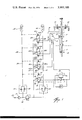
- FIG. 1 is a schematic diagram of one embodiment of the present invention
- FIG. 1A is a typical operation sequence schedule of the operation of the control system shown in FIG. 1,
- FIG. 2 is a schematic diagram of a further embodiment of the present invention.
- FIG. 2A is a typical operation sequence schedule of the operation of the control system shown in FIG. 2,
- FIG. 3 is an elevational view of a satisfactory valve assembly containing the hydraulic control valves of the present invention
- FIG. 4 is a cross-sectional view taken along the line 4--4 of FIG. 3,
- FIG. 5 is a cross-sectional view taken along the line 5--5 of FIG. 3,
- FIG. 6 is a cross-sectional view taken along the line 6--6 of FIG. 3, and
- FIG. 7 is a cross-sectional view taken along the line 7--7 of FIG. 3.
- a subsea oil production well 10 is shown to which various conventional equipment, which is required to be actuated hydraulically and remotely from an above water location, is connected.
- a subsurface safety valve 12 is connected to the well 10 and is urged to the closed position by a spring 14, but is hydraulically actuated to an open position through a hydraulic line 16.
- the subsurface safety valve may be of any conventional type such as the Camco B Series.
- the well may include a master valve 17 which is normally closed, but is actuated to the open position by a hydraulic actuator 18 through a line 20.
- the well may also include first and second wing valves 22 and 24 which are hydraulically actuated to an open position through lines 26 and 28, respectively.
- the present hydraulic control system is provided for controlling the hydraulically actuated underwater devices 12, 17, 22 and 24 from a single hydraulic control line 32 which performs the control function of opening and closing the devices 12, 17, 22 and 24, and preferably also provides the power actuating fluid for actuating the underwater devices.
- the control system 30 transmits its intelligence signals by specific and discrete pressure levels control valves to operate the devices 12, 17, 22 and 24 in a predetermined sequence of operation.
- a single hydraulic control line 32 is provided leading from a control point to underwater adjacent the production well 10.
- a filter 34 is provided for filtering the hydraulic fluid.
- a signal manifold 36 is connected to the single control line 32 and may be connected to an accumulator 38.
- a variable orifice valve 40 and check valve 42 are connected in parallel and positioned in the signal manifold 36 with the check valve directed to freely flow liquid out of the accumulator 38 and manifold 36 as will be more fully discussed hereinafter.
- a reference hydraulic manifold 44 preferably including an accumulator 46, is connected to the single control line 32 through a forward pressure regulator 48 which maintains the pressure in the reference manifold 44 at a predetermined pressure.
- a variable orifice valve 50 and check valve 52 are provided in parallel and positioned in the manifold 44 in which the check valve 52 is directed to freely flow fluid into the accumulator 46 as will be more fully discussed hereinafter.
- a plurality of pilot actuated hydraulic control valves 54, 54a, 54b, and 54c are provided, one of which is connected to each of the control devices.
- valve 54 is connected to line 16 for actuating subsurface safety valve 12
- control valve 54a is connected to line 20 for controlling master valve 17
- control valve 54b is connected to line 26 for controlling wing valve 22
- control valve 54c is connected to line 28 for controlling wing valve 24.
- Each of the control valves 54, 54a, 54b, and 54c includes an inlet and outlet for controlling the flow of hydraulic actuating fluid to its connected underwater device.
- valve 54 includes an inlet 56 and an outlet 58
- valve 54a includes an inlet 56a and an outlet 58a
- valve 54b includes an inlet 56b and an outlet 58b
- valve 54c includes an inlet 56c and an outlet 58c.
- the control valves may also include a dump outlet.
- valve 54 includes a dump outlet 60
- control valve 54a includes a dump outlet 60a
- control valve 54b includes a dump outlet 60b
- control valve 54c includes a dump outlet 60c.
- the outlets 58, 58a, 58b and 58c are connected to the actuating lines 16, 20, 26 and 28, respectively.
- the inlets 56, 56a, 56b and 56c are preferably connected to a common hydraulic power line 62.
- the line 62 may be a separate hydraulic power line for actuating the underwater devices 12, 16, 22 and 24, it is preferable that the line 62 be connected to the single control line 32 downstream of the pressure regulator 48 thereby providing a hydraulic control system 30 in which the single line 32 provides not only the control, but the power fluid for operating the underwater devices 12, 17, 22 and 24.
- control valve 54 includes a first pilot port 64 which is connected to the signal manifold 36 and a second pilot port 66 which is connected to the reference manifold 44.
- valves 54a, 54b and 54c include pilot ports 64a, 64b and 64c, respectively, which are connected to the signal manifold 36, and also include pilot ports 66a, 66b and 66c, respectively, which are connected to the reference manifold 44.
- valve block 70 which integrally contains all of the control valves 54, 54a, 54b and 54c.
- FIG. 4 cross-sectional view of valve 54 is best seen, shown in the dumping position, in which a valve element 72 is movable to provide communication between the inlet port 56 and the outlet port 58 in one position or, as shown blocks the inlet port 56 and provides communication between the outlet port 58 and the dump port 60 around the valve element 72.
- the control valve 54 includes a first piston 74 exposed to the pilot signal port 64 and a second piston 76 exposed to the pilot reference port 66.
- the pistons 74 and 76 are on opposite sides of seal element 72.
- the cross-sectional area of the pistons 74 and 76 are equal; therefore, the position of the valve element 72 will depend upon the relationship between the pressure in the reference manifold 44 and the pressure in the signal manifold 36. That is, when the pressure in the signal manifold 36 increases beyond the pressure in the reference manifold 44, the piston 74 will move the seal element 72 to provide communication between the inlet 56 and the outlet 58 to supply actuation fluid to the underwater device 12.
- the valves 54a, 54b and 54c similarly include second pistons 76a, 76b and 76c.
- the valves 54a, 54b and 54c include first pistons 74a, 74b and 74c.
- One way of obtaining this function is to provide that the ratios of the cross-sectional areas of the first pistons 74, 74a, 74b and 74c relative to the cross-sectional area of the second pistons 76, 76a, 76b, and 76c, respectively, of the valves are different from each other.
- first pistons 74, 74a, 74b and 74c decrease in cross-sectional area in sequence. Therefore, while the second pistons 76a, 76b and 76c in each of the valves may be of the same cross-sectional area, by serially decreasing the areas of the first pistons 74, 74a, 74b and 74c, the valves will be actuated in sequence as the pressure in the signal manifold 36 progressively increases to predetermined levels depending upon the pressure in the signal manifold 36, the pressure in the reference manifold 44, and the relative ratios of the cross-sectional areas of the first pistons relative to the second pistons.
- This quick input to the reference manifold 44 assures that the reference manifold 44 always arrives at its prescribed operational condition before the time delayed signal manifold 36 arrives at its prescribed operation.
- the variable orifice 50 in parallel with the check valve 52 in the reference manifold 44 provides a controlled delay in the out or bleed direction which assures that the reference manifold 44 will maintain its prescribed operational condition after the signal manifold 36 is bled down and loses its set condition and this arrangement further assures maximum fail safe condition.
- the hydraulic control valves 54, 54a, 54b and 54c have an actuation depending upon the pressures in the reference manifold 44, the signal manifold 36, and the ratios of their first and second pistons relative to each other.
- the ratios of the first piston to the second piston of each of the valves 54, 54a, 54b and 54c is such that valve 54 is moved from a closed to an open position on a signal pressure of 1500 pounds, valve 54a moves to an open position at 2000 pounds, valve 54b moves to an open position at 2500 pounds and valve 54c moves to an open position at 3000 pounds.
- valve 54 since the first and second pistons are equal, the valve 54 will move to the open position since the pressure in the signal manifold is slightly above 1500 pounds and the pressure in the reference manifold is only 1500 pounds, allowing the flow of actuating fluid from line 62 through the valve 54 and to hydraulic line 16 to actuate the subsurface safety valve 12.
- an intensifier 80 may be provided in the line 16 to increase the fluid pressure in the line 16 to that required to operate the normally closed fail safe subsurface safety valve 12 to the open position.
- valves 54a, 54b and 54c will not be actuated at this time because of the smaller cross-sectional areas of their first pistons relative to their second pistons.
- valve 54a When the pressure in the single control line 32 is increased until 2000 psi, valve 54a is actuated since the increased pressure of 2000 pounds acting on the similar first piston 74a overcomes the 1500 pound pressure acting on the larger second piston 76a (not shown), to open valve 54a and allow actuating fluid from line 62 to flow to line 20, at the regulator pressure of 1500 psi, to flow to a normally closed fail safe master gate valve 17 thereby opening the valve 17 into its open position. At this time, the pressure in the signal manifold 36 is not sufficient to actuate control valves 54b and 54c, but is still greater than the actuation of 1500 pounds to actuate valve 54 and therefore valve 54 remains opened.
- valve 54b is actuated to the open position flowing hydraulic actuating fluid from line 62 to line 26 to actuate wing valve 22 and move it into the open position. All conditions previously described will hold and persist until 3000 psi pressure level is obtained in the line 32 at which time valve 54c is actuated to the open position and hydraulic fluid from power line 62 will flow to line 28 to open wing valve 24.
- the closing order in FIGS. 1 and 1A is exactly the reverse of the opening order and any previous pressure level may be returned to which will close the control valves 54, 54a, 54b and 54c having a higher pressure, yet holding valves open which have a lower pressure threshold.
- the closing order proceeds as quickly as the pressure in line 32 is reduced since the pressure in the signal manifold 36 may be quickly dumped through the check valve 42 while the pressure in the reference manifold 44 is maintained through the time delay orifice 50.
- the signal pressure becomes less than 1500 psi
- all of the control valves 54, 54a, 54b and 54c are moved to the dumped position relieving the pressure in the lines 16, 26 and 28 thereby closing the valves 12, 17 and 24.
- any underwater fluid actuated device 12, 17 and 24 may be opened or closed in its specific order without regard to whether a complete closed cycle is performed.
- control system 30 shown in FIG. 1 is designed so that each of the control valves 54, 54a, 54b and 54c operate at a predetermined sequence and pressure level, they are positioned in parallel and their operation is independent of each other.
- the circuitry of the control system 30 may be varied to provide a varied operating sequence.
- the hydraulic control valves 54, 54a, 54b and 54c are connected in series. That is, only the inlet 56 of valve 54 is connected to the power line 62. The inlet 56a of valve 54a is connected to the outlet 58 of valve 54. Therefore, valve 54a is unable to transmit actuating fluid to line 20, even though valve 54a is actuated to the open position until valve 54 is opened.
- valve 54b is connected to the outlet 58a of valve 54a
- inlet 56b of valve 54c is connected to the outlet 58b of valve 54b.
- FIG. 2 A varied operating sequence is achieved in FIG. 2 by rearranging the power ports of valve 54c so that valve 54c in FIG. 2 is in the normally opened position instead of the dump position. Therefore, as indicated in the operating schedule in FIG. 2A, while the operation and sequence of the system of FIG. 2 is the same as that shown in FIGS. 1 and 1A for the first three sequencing steps, the operation becomes different when the pressure in the control line 32 reaches 2500 pounds. That is, at 2500 pounds, valve 54b is opened which supplies actuating fluid to line 28 to actuate wing valve 24.
- control valve 54c is normally open, actuating fluid from port 58b of valve 54b flows through the inlet 56c and outlet 58c of the control valve 54c to simultaneously supply actuating fluid to line 26 and actuate wing valve 22. Then, when the pressure in the control line 32 reaches 3000 pounds, valve 54c is actuated to the dump position closing wing valve 22. Therefore, by selective connection of the circuitry, variations in the operating sequence may be provided.
Landscapes
- Life Sciences & Earth Sciences (AREA)
- Engineering & Computer Science (AREA)
- Geology (AREA)
- Mining & Mineral Resources (AREA)
- Physics & Mathematics (AREA)
- Environmental & Geological Engineering (AREA)
- Fluid Mechanics (AREA)
- General Life Sciences & Earth Sciences (AREA)
- Geochemistry & Mineralogy (AREA)
- Fluid-Pressure Circuits (AREA)
Abstract
Description
Claims (12)
Applications Claiming Priority (2)
| Application Number | Priority Date | Filing Date | Title |
|---|---|---|---|
| GB18753/74A GB1505496A (en) | 1974-04-29 | 1974-04-29 | Hydraulic control system for controlling hydraulically actuated underwater devices |
| UK18753/74 | 1974-04-29 |
Publications (1)
| Publication Number | Publication Date |
|---|---|
| US3993100A true US3993100A (en) | 1976-11-23 |
Family
ID=10117819
Family Applications (1)
| Application Number | Title | Priority Date | Filing Date |
|---|---|---|---|
| US05/572,039 Expired - Lifetime US3993100A (en) | 1974-04-29 | 1975-04-28 | Hydraulic control system for controlling a plurality of underwater devices |
Country Status (2)
| Country | Link |
|---|---|
| US (1) | US3993100A (en) |
| GB (1) | GB1505496A (en) |
Cited By (96)
| Publication number | Priority date | Publication date | Assignee | Title |
|---|---|---|---|---|
| US4036247A (en) * | 1976-03-15 | 1977-07-19 | Vetco Offshore Industries, Inc. | Multi-pressure, single line supply system |
| FR2423807A1 (en) * | 1978-04-17 | 1979-11-16 | Europ Propulsion | Remote control system esp. for submerged equipment - incorporates operating module, connected to surface control station, equipped with local electrical energy generator |
| US4185541A (en) * | 1977-02-26 | 1980-01-29 | Fmc Corporation | Method and apparatus for hydraulically controlling subsea well equipment |
| US4185652A (en) * | 1977-10-31 | 1980-01-29 | Nl Industries, Inc. | Subaqueous sequence valve mechanism |
| EP0009364A3 (en) * | 1978-09-27 | 1980-05-28 | Fmc Corporation | Apparatus for extending control from a surface location to a subsea station |
| US4271867A (en) * | 1978-01-30 | 1981-06-09 | Fmc Corporation | Method and apparatus for hydraulically controlling subsea well equipment |
| US4308884A (en) * | 1980-07-24 | 1982-01-05 | Exxon Production Research Company | Method for transmission of pressure signals through a conduit |
| FR2493423A1 (en) * | 1980-10-31 | 1982-05-07 | Flopetrol Etudes Fabric | METHOD AND SYSTEM FOR HYDRAULIC CONTROL, IN PARTICULAR UNDERWATER VALVES |
| US4353721A (en) * | 1980-05-09 | 1982-10-12 | Zinser Textilmaschinen Gmbh | Exhaust system for removing airborne particles from the vicinity of textile machinery |
| WO1982003887A1 (en) * | 1981-05-01 | 1982-11-11 | Hurta Gary Lee | Hydraulic control of subsea well equipment |
| US4467833A (en) * | 1977-10-11 | 1984-08-28 | Nl Industries, Inc. | Control valve and electrical and hydraulic control system |
| US4497369A (en) * | 1981-08-13 | 1985-02-05 | Combustion Engineering, Inc. | Hydraulic control of subsea well equipment |
| US4549578A (en) * | 1984-03-21 | 1985-10-29 | Exxon Production Research Co. | Coded fluid control system |
| US4596375A (en) * | 1981-08-13 | 1986-06-24 | Vetco Offshore, Inc. | Hydraulic control of subsea well equipment |
| US4923008A (en) * | 1989-01-16 | 1990-05-08 | Baroid Technology, Inc. | Hydraulic power system and method |
| US5027847A (en) * | 1989-11-08 | 1991-07-02 | Axelson Incorporated | Pneumatic valve actuator sequencing control system and sequencing relay device incorporated therein |
| US5188180A (en) * | 1991-08-13 | 1993-02-23 | Abb Vetco Gray Inc. | Hydraulic circuit for a well tool |
| EP0584997A3 (en) * | 1992-08-11 | 1994-06-29 | Halliburton Co | Downhole tool operating system and method |
| US5409040A (en) * | 1993-08-09 | 1995-04-25 | Koomey Companies International, Inc. | Springless pilot operated sequence valve |
| GB2335216A (en) * | 1998-03-13 | 1999-09-15 | Abb Seatec Ltd | Extraction of fluid from wells |
| WO1999047788A1 (en) * | 1998-03-13 | 1999-09-23 | Abb Offshore Systems Limited | Well control |
| US6247536B1 (en) | 1998-07-14 | 2001-06-19 | Camco International Inc. | Downhole multiplexer and related methods |
| US6315049B1 (en) * | 1998-10-07 | 2001-11-13 | Baker Hughes Incorporated | Multiple line hydraulic system flush valve and method of use |
| EP0923690A4 (en) * | 1997-02-21 | 2002-01-16 | Integrated power and control system | |
| US20030048197A1 (en) * | 2000-02-22 | 2003-03-13 | Purkis Daniel G. | Sequential hydraulic control system for use in a subterranean well |
| US6575237B2 (en) | 1998-08-13 | 2003-06-10 | Welldynamics, Inc. | Hydraulic well control system |
| US20040050555A1 (en) * | 2002-09-13 | 2004-03-18 | Rayssiguier Christophe M. | System and method for controlling downhole tools |
| US20040055749A1 (en) * | 2002-09-23 | 2004-03-25 | Lonnes Steven B. | Remote intervention logic valving method and apparatus |
| US20050087344A1 (en) * | 2003-10-24 | 2005-04-28 | Schlumberger Technology Corporation | System and Method to Control Multiple Tools Through One Control Line |
| US20060162935A1 (en) * | 2005-01-25 | 2006-07-27 | Schlumberger Technology Corporation | Snorkel Device for Flow Control |
| US20080223467A1 (en) * | 2007-03-16 | 2008-09-18 | Fmc Kongsberg Subsea As | Method and device for regulating a pressure in a hydraulic system |
| GB2448434A (en) * | 2006-02-02 | 2008-10-15 | Schlumberger Holdings | Snorkel device for flow control |
| RU2352760C1 (en) * | 2008-05-20 | 2009-04-20 | Закрытое Акционерное Общество Финансовая Компания "Центр-Космос-Нефть-Газ" | Gas condensate well |
| RU2352758C1 (en) * | 2008-05-20 | 2009-04-20 | Общество с ограниченной ответственностью Финансово-промышленная компания "Космос-Нефть-Газ" | Equipment complex for controlling gas-condensate deposit well |
| RU2352759C1 (en) * | 2008-05-20 | 2009-04-20 | Закрытое Акционерное Общество Финансовая Компания "Центр-Космос-Нефть-Газ" | Gas well |
| RU2365737C1 (en) * | 2008-05-20 | 2009-08-27 | Общество с ограниченной ответственностью Финансово-промышленная компания "Космос-Нефть-Газ" | Complex of equipment for control of oil pool well |
| RU2365738C1 (en) * | 2008-05-20 | 2009-08-27 | Закрытое акционерное общество Финансовая компания "Центр-Космос- Нефть-Газ" | Oil and gas well |
| RU2367779C1 (en) * | 2008-05-20 | 2009-09-20 | Закрытое Акционерное Общество Финансовая Компания "Центр-Космос-Нефть-Газ" | Method of exploiting oil field |
| RU2367772C1 (en) * | 2008-05-20 | 2009-09-20 | Закрытое Акционерное Общество Финансовая Компания "Центр-Космос-Нефть-Газ" | Oil well pad |
| RU2367790C1 (en) * | 2008-05-20 | 2009-09-20 | Закрытое Акционерное Общество Финансовая Компания "Центр-Космос-Нефть-Газ" | Method of controlling oil-gas field |
| RU2367789C1 (en) * | 2008-05-20 | 2009-09-20 | Закрытое Акционерное Общество Финансовая Компания "Центр-Космос-Нефть-Газ" | Method of controlling gas-field |
| RU2367781C1 (en) * | 2008-05-20 | 2009-09-20 | Закрытое Акционерное Общество Финансовая Компания "Центр-Космос-Нефть-Газ" | Recovery method of gas condensate |
| RU2367783C1 (en) * | 2008-05-20 | 2009-09-20 | Закрытое Акционерное Общество Финансовая Компания "Центр-Космос-Нефть-Газ" | Method of exploiting gas-condensate field |
| RU2367770C1 (en) * | 2008-05-20 | 2009-09-20 | Закрытое Акционерное Общество Финансовая Компания "Центр-Космос-Нефть-Газ" | Equipment system for gas field well controlling |
| RU2367784C1 (en) * | 2008-05-20 | 2009-09-20 | Закрытое Акционерное Общество Финансовая Компания "Центр-Космос-Нефть-Газ" | Method of controlling gas-condensate field |
| RU2367769C1 (en) * | 2008-05-20 | 2009-09-20 | Закрытое Акционерное Общество Финансовая Компания "Центр-Космос-Нефть-Газ" | Oil and gas well pad |
| RU2367782C1 (en) * | 2008-05-20 | 2009-09-20 | Закрытое Акционерное Общество Финансовая Компания "Центр-Космос-Нефть-Газ" | Method of exploiting gas field |
| RU2367785C1 (en) * | 2008-05-20 | 2009-09-20 | Закрытое Акционерное Общество Финансовая Компания "Центр-Космос-Нефть-Газ" | Method of controlling oil field |
| RU2367778C1 (en) * | 2008-05-20 | 2009-09-20 | Закрытое Акционерное Общество Финансовая Компания "Центр-Космос-Нефть-Газ" | Method of exploiting oil-gas field |
| RU2367777C1 (en) * | 2008-05-20 | 2009-09-20 | Закрытое Акционерное Общество Финансовая Компания "Центр-Космос-Нефть-Газ" | Oil extraction method |
| RU2367786C1 (en) * | 2008-05-20 | 2009-09-20 | Закрытое Акционерное Общество Финансовая Компания "Центр-Космос-Нефть-Газ" | Oil well |
| RU2367771C1 (en) * | 2008-05-20 | 2009-09-20 | Иван Георгиевич Лачугин | Equipment system for gas field well controlling |
| RU2367787C1 (en) * | 2008-05-20 | 2009-09-20 | Закрытое Акционерное Общество Финансовая Компания "Центр-Космос-Нефть-Газ" | Gas well pad |
| RU2367776C1 (en) * | 2008-05-20 | 2009-09-20 | Закрытое Акционерное Общество Финансовая Компания "Центр-Космос-Нефть-Газ" | Gas extraction method |
| RU2367788C1 (en) * | 2008-05-20 | 2009-09-20 | Закрытое Акционерное Общество Финансовая Компания "Центр-Космос-Нефть-Газ" | Gas-condensate well pad |
| RU2372473C1 (en) * | 2008-06-18 | 2009-11-10 | Селиванов Николай Павлович | Procedure of operating gas field and gas-condensate field |
| RU2373380C1 (en) * | 2008-06-18 | 2009-11-20 | Селиванов Николай Павлович | Method for development of gas or gas-condensate deposit |
| RU2373381C1 (en) * | 2008-06-18 | 2009-11-20 | Селиванов Николай Павлович | Method for development of gas or gas-condensate deposit |
| WO2009132300A3 (en) * | 2008-04-24 | 2010-01-28 | Cameron International Corporation | Subsea pressure delivery system |
| EA013310B1 (en) * | 2008-05-20 | 2010-04-30 | Закрытое Акционерное Общество Финансовая Компания "Центр-Космос-Нефть-Газ" | Methods for controling x-mass tree and underground equipment of wells in gas, gas-condensate, oil-and gas and oil fields |
| EA013309B1 (en) * | 2008-05-20 | 2010-04-30 | Закрытое Акционерное Общество Финансовая Компания "Центр-Космос-Нефть-Газ" | Method of gas, gas condensate and oil production (embodiments) |
| EA013727B1 (en) * | 2008-05-20 | 2010-06-30 | Закрытое Акционерное Общество Финансовая Компания "Центр-Космос-Нефть-Газ" | Remote-controlled downhole equipment of gas, gas-condensate, oil-gas, oil deposits well cluster |
| EA013726B1 (en) * | 2008-05-20 | 2010-06-30 | Закрытое Акционерное Общество Финансовая Компания "Центр-Космос-Нефть-Газ" | Gas, gas-condensate and oil wells with remote-controlled downhole equipment |
| GB2472475A (en) * | 2009-08-05 | 2011-02-09 | Dril Quip Inc | Subsea control system including a number of dual ball valve assemblies |
| US20110192480A1 (en) * | 2010-02-08 | 2011-08-11 | Baker Hughes Incorporated | Valving System and Method of Selectively Halting Injection of Chemicals |
| RU2453686C1 (en) * | 2010-11-18 | 2012-06-20 | Общество с ограниченной ответственностью Финансово-промышленная компания "Космос-Нефть-Газ" | Control method of shutoff-control valves of well cluster, and device for its implementation |
| RU2453687C1 (en) * | 2010-11-18 | 2012-06-20 | Общество с ограниченной ответственностью Финансово-промышленная компания "Космос-Нефть-Газ" | Well of hydrocarbon raw material deposit |
| RU2453685C1 (en) * | 2010-11-18 | 2012-06-20 | Общество с ограниченной ответственностью Финансово-промышленная компания "Космос-Нефть-Газ" | Operating method of hydrocarbon raw material deposit |
| RU2453684C1 (en) * | 2010-11-18 | 2012-06-20 | Общество с ограниченной ответственностью Финансово-промышленная компания "Космос-Нефть-Газ" | Well cluster of hydrocarbon raw material deposit |
| US20120175125A1 (en) * | 2010-11-15 | 2012-07-12 | Oceaneering International, Inc. | Subsea pod pump |
| US20120247831A1 (en) * | 2009-09-22 | 2012-10-04 | Statoil Asa | Control method and apparatus for well operations |
| RU2494301C1 (en) * | 2012-03-13 | 2013-09-27 | Рафик Хасанович Арифулин | Christmas tree |
| US20150129233A1 (en) * | 2013-11-12 | 2015-05-14 | Shell Oil Company | Assembly and System Including a Surge Relief Valve |
| RU2559268C1 (en) * | 2014-02-12 | 2015-08-10 | Общество с ограниченной ответственностью "Газпром добыча Ноябрьск" (ООО "Газпром добыча Ноябрьск) | Adaptive control system for productivity of gas well pad |
| RU2571462C2 (en) * | 2010-04-01 | 2015-12-20 | Роберт Бош Гмбх | Valves for fossil fuel production and transport with safety unit |
| RU2571701C2 (en) * | 2010-04-01 | 2015-12-20 | Роберт Бош Гмбх | Valves for fossil fuel production and transport with safety unit |
| WO2016069120A1 (en) * | 2014-10-27 | 2016-05-06 | Baker Hughes Incorporated | Control system including single line switches and method |
| RU2591870C1 (en) * | 2015-04-17 | 2016-07-20 | Федеральное государственное бюджетное учреждение науки Институт проблем управления им. В.А. Трапезникова Российской академии наук | Method for adaptive automatic control of gas condensate wells |
| WO2017083647A1 (en) * | 2015-11-13 | 2017-05-18 | Cameron International Corporation | Fracturing fluid delivery system |
| EP3049322A4 (en) * | 2013-09-27 | 2017-08-02 | Oceaneering International Inc. | An integrated hydraulic skid system incorporated into a rapid release emergency disconnect system |
| RU173107U1 (en) * | 2017-03-06 | 2017-08-11 | Общество с ограниченной ответственностью "Газпром добыча Уренгой" | GAS-LIFT GAS CONTROL AND SUPPLY DEVICE FOR WELL OPERATION USING PERMANENT AND PERIODIC GAS LIFT |
| RU2643884C1 (en) * | 2017-01-25 | 2018-02-06 | Общество с ограниченной ответственностью "Газпром добыча Ямбург" | Method of automatic control of technological processes of gas and gas condensate wells |
| CN108561101A (en) * | 2018-01-10 | 2018-09-21 | 中国海洋石油集团有限公司 | A kind of intelligent well completion device of long-range closed loop pilot-operated type control |
| US10145208B2 (en) * | 2015-04-30 | 2018-12-04 | Conocophillips Company | Annulus installed 6 zone control manifold |
| US10365669B2 (en) | 2015-09-18 | 2019-07-30 | The Oilgear Company | Systems and methods for fluid regulation |
| US10385645B2 (en) | 2011-09-23 | 2019-08-20 | Cameron International Corporation | Fracturing manifold systems and methods |
| US10385662B2 (en) | 2012-01-11 | 2019-08-20 | Cameron International Corporation | Well fracturing manifold apparatus |
| US10487637B2 (en) | 2011-09-23 | 2019-11-26 | Cameron International Corporation | Adjustable fracturing system |
| US10508745B2 (en) | 2015-09-18 | 2019-12-17 | The Oilgear Company | Valve assembly |
| US10677017B2 (en) * | 2013-12-05 | 2020-06-09 | Schlumberger Technology Corporation | System and methodology for utilizing a flow control valve |
| US11015413B2 (en) | 2018-10-31 | 2021-05-25 | Cameron International Corporation | Fracturing system with fluid conduit having communication line |
| US11066913B2 (en) | 2016-05-01 | 2021-07-20 | Cameron International Corporation | Flexible fracturing line with removable liner |
| RU2760834C1 (en) * | 2021-03-22 | 2021-11-30 | Общество с ограниченной ответственностью "Газпром добыча Ямбург" | Method for automatic maintenance of gas consumption of integrated gas treatment plants in the arctic regions |
| US11319757B2 (en) | 2019-12-26 | 2022-05-03 | Cameron International Corporation | Flexible fracturing fluid delivery conduit quick connectors |
| RU2783981C1 (en) * | 2022-06-30 | 2022-11-23 | Общество с ограниченной ответственностью "РусГазШельф" | System and method for shut-off valves closing of underwater gas field |
| WO2025248236A1 (en) * | 2024-05-27 | 2025-12-04 | Wellvene Limited | Hydraulically actuatable safety valve |
Families Citing this family (1)
| Publication number | Priority date | Publication date | Assignee | Title |
|---|---|---|---|---|
| NO317432B1 (en) | 2002-12-23 | 2004-10-25 | Bakke Oil Tools As | Method and apparatus for pressure controlled sequence control |
Citations (2)
| Publication number | Priority date | Publication date | Assignee | Title |
|---|---|---|---|---|
| US1905065A (en) * | 1929-12-16 | 1933-04-25 | Zimmermann & Jansen Gmbh | Valve actuating means for air heaters |
| US3014490A (en) * | 1957-12-26 | 1961-12-26 | John U Morris | Fluid control system and apparatus |
-
1974
- 1974-04-29 GB GB18753/74A patent/GB1505496A/en not_active Expired
-
1975
- 1975-04-28 US US05/572,039 patent/US3993100A/en not_active Expired - Lifetime
Patent Citations (2)
| Publication number | Priority date | Publication date | Assignee | Title |
|---|---|---|---|---|
| US1905065A (en) * | 1929-12-16 | 1933-04-25 | Zimmermann & Jansen Gmbh | Valve actuating means for air heaters |
| US3014490A (en) * | 1957-12-26 | 1961-12-26 | John U Morris | Fluid control system and apparatus |
Cited By (133)
| Publication number | Priority date | Publication date | Assignee | Title |
|---|---|---|---|---|
| US4036247A (en) * | 1976-03-15 | 1977-07-19 | Vetco Offshore Industries, Inc. | Multi-pressure, single line supply system |
| US4185541A (en) * | 1977-02-26 | 1980-01-29 | Fmc Corporation | Method and apparatus for hydraulically controlling subsea well equipment |
| US4280531A (en) * | 1977-02-26 | 1981-07-28 | Fmc Corporation | Method and apparatus for hydraulically controlling subsea well equipment |
| US4467833A (en) * | 1977-10-11 | 1984-08-28 | Nl Industries, Inc. | Control valve and electrical and hydraulic control system |
| US4185652A (en) * | 1977-10-31 | 1980-01-29 | Nl Industries, Inc. | Subaqueous sequence valve mechanism |
| US4271867A (en) * | 1978-01-30 | 1981-06-09 | Fmc Corporation | Method and apparatus for hydraulically controlling subsea well equipment |
| FR2423807A1 (en) * | 1978-04-17 | 1979-11-16 | Europ Propulsion | Remote control system esp. for submerged equipment - incorporates operating module, connected to surface control station, equipped with local electrical energy generator |
| EP0009364A3 (en) * | 1978-09-27 | 1980-05-28 | Fmc Corporation | Apparatus for extending control from a surface location to a subsea station |
| US4407183A (en) * | 1978-09-27 | 1983-10-04 | Fmc Corporation | Method and apparatus for hydraulically controlling subsea equipment |
| US4353721A (en) * | 1980-05-09 | 1982-10-12 | Zinser Textilmaschinen Gmbh | Exhaust system for removing airborne particles from the vicinity of textile machinery |
| FR2487470A1 (en) * | 1980-07-24 | 1982-01-29 | Exxon Research Engineering Co | METHOD FOR TRANSMITTING PRESSURE SIGNALS THROUGH PIPING AND FOR CONTROLLING THE ACTUATION OF A DEVICE CONNECTED TO SUCH A PIPING |
| US4308884A (en) * | 1980-07-24 | 1982-01-05 | Exxon Production Research Company | Method for transmission of pressure signals through a conduit |
| FR2493423A1 (en) * | 1980-10-31 | 1982-05-07 | Flopetrol Etudes Fabric | METHOD AND SYSTEM FOR HYDRAULIC CONTROL, IN PARTICULAR UNDERWATER VALVES |
| US4442902A (en) * | 1980-10-31 | 1984-04-17 | Schlumberger Technology Corporation | Remote hydraulic control method and apparatus, notably for underwater valves |
| WO1982003887A1 (en) * | 1981-05-01 | 1982-11-11 | Hurta Gary Lee | Hydraulic control of subsea well equipment |
| US4497369A (en) * | 1981-08-13 | 1985-02-05 | Combustion Engineering, Inc. | Hydraulic control of subsea well equipment |
| US4596375A (en) * | 1981-08-13 | 1986-06-24 | Vetco Offshore, Inc. | Hydraulic control of subsea well equipment |
| US4549578A (en) * | 1984-03-21 | 1985-10-29 | Exxon Production Research Co. | Coded fluid control system |
| US4923008A (en) * | 1989-01-16 | 1990-05-08 | Baroid Technology, Inc. | Hydraulic power system and method |
| US5027847A (en) * | 1989-11-08 | 1991-07-02 | Axelson Incorporated | Pneumatic valve actuator sequencing control system and sequencing relay device incorporated therein |
| US5188180A (en) * | 1991-08-13 | 1993-02-23 | Abb Vetco Gray Inc. | Hydraulic circuit for a well tool |
| EP0584997A3 (en) * | 1992-08-11 | 1994-06-29 | Halliburton Co | Downhole tool operating system and method |
| US5409040A (en) * | 1993-08-09 | 1995-04-25 | Koomey Companies International, Inc. | Springless pilot operated sequence valve |
| EP0923690A4 (en) * | 1997-02-21 | 2002-01-16 | Integrated power and control system | |
| GB2335216A (en) * | 1998-03-13 | 1999-09-15 | Abb Seatec Ltd | Extraction of fluid from wells |
| WO1999047788A1 (en) * | 1998-03-13 | 1999-09-23 | Abb Offshore Systems Limited | Well control |
| US6247536B1 (en) | 1998-07-14 | 2001-06-19 | Camco International Inc. | Downhole multiplexer and related methods |
| US6567013B1 (en) | 1998-08-13 | 2003-05-20 | Halliburton Energy Services, Inc. | Digital hydraulic well control system |
| US6575237B2 (en) | 1998-08-13 | 2003-06-10 | Welldynamics, Inc. | Hydraulic well control system |
| US6315049B1 (en) * | 1998-10-07 | 2001-11-13 | Baker Hughes Incorporated | Multiple line hydraulic system flush valve and method of use |
| US20030048197A1 (en) * | 2000-02-22 | 2003-03-13 | Purkis Daniel G. | Sequential hydraulic control system for use in a subterranean well |
| US7145471B2 (en) | 2000-02-22 | 2006-12-05 | Welldynamics, Inc. | Sequential hydraulic control system for use in a subterranean well |
| US20040050555A1 (en) * | 2002-09-13 | 2004-03-18 | Rayssiguier Christophe M. | System and method for controlling downhole tools |
| US7182139B2 (en) | 2002-09-13 | 2007-02-27 | Schlumberger Technology Corporation | System and method for controlling downhole tools |
| US20040055749A1 (en) * | 2002-09-23 | 2004-03-25 | Lonnes Steven B. | Remote intervention logic valving method and apparatus |
| US7516792B2 (en) | 2002-09-23 | 2009-04-14 | Exxonmobil Upstream Research Company | Remote intervention logic valving method and apparatus |
| US20050087344A1 (en) * | 2003-10-24 | 2005-04-28 | Schlumberger Technology Corporation | System and Method to Control Multiple Tools Through One Control Line |
| US7306043B2 (en) | 2003-10-24 | 2007-12-11 | Schlumberger Technology Corporation | System and method to control multiple tools through one control line |
| US20060162935A1 (en) * | 2005-01-25 | 2006-07-27 | Schlumberger Technology Corporation | Snorkel Device for Flow Control |
| US7455114B2 (en) | 2005-01-25 | 2008-11-25 | Schlumberger Technology Corporation | Snorkel device for flow control |
| GB2448434A (en) * | 2006-02-02 | 2008-10-15 | Schlumberger Holdings | Snorkel device for flow control |
| GB2448434B (en) * | 2006-02-02 | 2010-08-04 | Schlumberger Holdings | Snorkel device for flow control |
| US8156953B2 (en) * | 2007-03-16 | 2012-04-17 | Fmc Kongsberg Subsea As | Method and device for regulating a pressure in a hydraulic system |
| NO329453B1 (en) * | 2007-03-16 | 2010-10-25 | Fmc Kongsberg Subsea As | Pressure control device and method |
| US20080223467A1 (en) * | 2007-03-16 | 2008-09-18 | Fmc Kongsberg Subsea As | Method and device for regulating a pressure in a hydraulic system |
| GB2471824A (en) * | 2008-04-24 | 2011-01-12 | Cameron Int Corp | Subsea pressure delivery system |
| WO2009132300A3 (en) * | 2008-04-24 | 2010-01-28 | Cameron International Corporation | Subsea pressure delivery system |
| GB2471824B (en) * | 2008-04-24 | 2012-11-14 | Cameron Int Corp | Subsea pressure delivery system |
| US9222326B2 (en) | 2008-04-24 | 2015-12-29 | Cameron International Corporation | Subsea pressure delivery system |
| RU2367790C1 (en) * | 2008-05-20 | 2009-09-20 | Закрытое Акционерное Общество Финансовая Компания "Центр-Космос-Нефть-Газ" | Method of controlling oil-gas field |
| RU2367787C1 (en) * | 2008-05-20 | 2009-09-20 | Закрытое Акционерное Общество Финансовая Компания "Центр-Космос-Нефть-Газ" | Gas well pad |
| RU2367781C1 (en) * | 2008-05-20 | 2009-09-20 | Закрытое Акционерное Общество Финансовая Компания "Центр-Космос-Нефть-Газ" | Recovery method of gas condensate |
| RU2367783C1 (en) * | 2008-05-20 | 2009-09-20 | Закрытое Акционерное Общество Финансовая Компания "Центр-Космос-Нефть-Газ" | Method of exploiting gas-condensate field |
| RU2367770C1 (en) * | 2008-05-20 | 2009-09-20 | Закрытое Акционерное Общество Финансовая Компания "Центр-Космос-Нефть-Газ" | Equipment system for gas field well controlling |
| RU2367784C1 (en) * | 2008-05-20 | 2009-09-20 | Закрытое Акционерное Общество Финансовая Компания "Центр-Космос-Нефть-Газ" | Method of controlling gas-condensate field |
| RU2367769C1 (en) * | 2008-05-20 | 2009-09-20 | Закрытое Акционерное Общество Финансовая Компания "Центр-Космос-Нефть-Газ" | Oil and gas well pad |
| RU2367782C1 (en) * | 2008-05-20 | 2009-09-20 | Закрытое Акционерное Общество Финансовая Компания "Центр-Космос-Нефть-Газ" | Method of exploiting gas field |
| RU2367785C1 (en) * | 2008-05-20 | 2009-09-20 | Закрытое Акционерное Общество Финансовая Компания "Центр-Космос-Нефть-Газ" | Method of controlling oil field |
| RU2367778C1 (en) * | 2008-05-20 | 2009-09-20 | Закрытое Акционерное Общество Финансовая Компания "Центр-Космос-Нефть-Газ" | Method of exploiting oil-gas field |
| RU2367777C1 (en) * | 2008-05-20 | 2009-09-20 | Закрытое Акционерное Общество Финансовая Компания "Центр-Космос-Нефть-Газ" | Oil extraction method |
| RU2367786C1 (en) * | 2008-05-20 | 2009-09-20 | Закрытое Акционерное Общество Финансовая Компания "Центр-Космос-Нефть-Газ" | Oil well |
| RU2367771C1 (en) * | 2008-05-20 | 2009-09-20 | Иван Георгиевич Лачугин | Equipment system for gas field well controlling |
| RU2367789C1 (en) * | 2008-05-20 | 2009-09-20 | Закрытое Акционерное Общество Финансовая Компания "Центр-Космос-Нефть-Газ" | Method of controlling gas-field |
| RU2367776C1 (en) * | 2008-05-20 | 2009-09-20 | Закрытое Акционерное Общество Финансовая Компания "Центр-Космос-Нефть-Газ" | Gas extraction method |
| RU2367788C1 (en) * | 2008-05-20 | 2009-09-20 | Закрытое Акционерное Общество Финансовая Компания "Центр-Космос-Нефть-Газ" | Gas-condensate well pad |
| RU2367772C1 (en) * | 2008-05-20 | 2009-09-20 | Закрытое Акционерное Общество Финансовая Компания "Центр-Космос-Нефть-Газ" | Oil well pad |
| RU2367779C1 (en) * | 2008-05-20 | 2009-09-20 | Закрытое Акционерное Общество Финансовая Компания "Центр-Космос-Нефть-Газ" | Method of exploiting oil field |
| RU2365738C1 (en) * | 2008-05-20 | 2009-08-27 | Закрытое акционерное общество Финансовая компания "Центр-Космос- Нефть-Газ" | Oil and gas well |
| RU2365737C1 (en) * | 2008-05-20 | 2009-08-27 | Общество с ограниченной ответственностью Финансово-промышленная компания "Космос-Нефть-Газ" | Complex of equipment for control of oil pool well |
| EA013310B1 (en) * | 2008-05-20 | 2010-04-30 | Закрытое Акционерное Общество Финансовая Компания "Центр-Космос-Нефть-Газ" | Methods for controling x-mass tree and underground equipment of wells in gas, gas-condensate, oil-and gas and oil fields |
| EA013309B1 (en) * | 2008-05-20 | 2010-04-30 | Закрытое Акционерное Общество Финансовая Компания "Центр-Космос-Нефть-Газ" | Method of gas, gas condensate and oil production (embodiments) |
| EA013727B1 (en) * | 2008-05-20 | 2010-06-30 | Закрытое Акционерное Общество Финансовая Компания "Центр-Космос-Нефть-Газ" | Remote-controlled downhole equipment of gas, gas-condensate, oil-gas, oil deposits well cluster |
| EA013726B1 (en) * | 2008-05-20 | 2010-06-30 | Закрытое Акционерное Общество Финансовая Компания "Центр-Космос-Нефть-Газ" | Gas, gas-condensate and oil wells with remote-controlled downhole equipment |
| RU2352759C1 (en) * | 2008-05-20 | 2009-04-20 | Закрытое Акционерное Общество Финансовая Компания "Центр-Космос-Нефть-Газ" | Gas well |
| RU2352758C1 (en) * | 2008-05-20 | 2009-04-20 | Общество с ограниченной ответственностью Финансово-промышленная компания "Космос-Нефть-Газ" | Equipment complex for controlling gas-condensate deposit well |
| RU2352760C1 (en) * | 2008-05-20 | 2009-04-20 | Закрытое Акционерное Общество Финансовая Компания "Центр-Космос-Нефть-Газ" | Gas condensate well |
| RU2373380C1 (en) * | 2008-06-18 | 2009-11-20 | Селиванов Николай Павлович | Method for development of gas or gas-condensate deposit |
| RU2373381C1 (en) * | 2008-06-18 | 2009-11-20 | Селиванов Николай Павлович | Method for development of gas or gas-condensate deposit |
| RU2372473C1 (en) * | 2008-06-18 | 2009-11-10 | Селиванов Николай Павлович | Procedure of operating gas field and gas-condensate field |
| GB2472475A (en) * | 2009-08-05 | 2011-02-09 | Dril Quip Inc | Subsea control system including a number of dual ball valve assemblies |
| US9695655B2 (en) * | 2009-09-22 | 2017-07-04 | Statoil Petroleum As | Control method and apparatus for well operations |
| US20120247831A1 (en) * | 2009-09-22 | 2012-10-04 | Statoil Asa | Control method and apparatus for well operations |
| US8857454B2 (en) * | 2010-02-08 | 2014-10-14 | Baker Hughes Incorporated | Valving system and method of selectively halting injection of chemicals |
| US20110192480A1 (en) * | 2010-02-08 | 2011-08-11 | Baker Hughes Incorporated | Valving System and Method of Selectively Halting Injection of Chemicals |
| RU2571462C9 (en) * | 2010-04-01 | 2016-05-27 | Роберт Бош Гмбх | Valves for fossil fuel production and transport with safety unit |
| RU2571462C2 (en) * | 2010-04-01 | 2015-12-20 | Роберт Бош Гмбх | Valves for fossil fuel production and transport with safety unit |
| RU2571701C2 (en) * | 2010-04-01 | 2015-12-20 | Роберт Бош Гмбх | Valves for fossil fuel production and transport with safety unit |
| US20120175125A1 (en) * | 2010-11-15 | 2012-07-12 | Oceaneering International, Inc. | Subsea pod pump |
| RU2453686C1 (en) * | 2010-11-18 | 2012-06-20 | Общество с ограниченной ответственностью Финансово-промышленная компания "Космос-Нефть-Газ" | Control method of shutoff-control valves of well cluster, and device for its implementation |
| RU2453684C1 (en) * | 2010-11-18 | 2012-06-20 | Общество с ограниченной ответственностью Финансово-промышленная компания "Космос-Нефть-Газ" | Well cluster of hydrocarbon raw material deposit |
| RU2453687C1 (en) * | 2010-11-18 | 2012-06-20 | Общество с ограниченной ответственностью Финансово-промышленная компания "Космос-Нефть-Газ" | Well of hydrocarbon raw material deposit |
| RU2453685C1 (en) * | 2010-11-18 | 2012-06-20 | Общество с ограниченной ответственностью Финансово-промышленная компания "Космос-Нефть-Газ" | Operating method of hydrocarbon raw material deposit |
| US10876371B2 (en) | 2011-09-23 | 2020-12-29 | Cameron International Corporation | Fracturing manifold system |
| US10385643B2 (en) | 2011-09-23 | 2019-08-20 | Cameron International Corporation | Fracturing manifold systems and methods |
| US10385645B2 (en) | 2011-09-23 | 2019-08-20 | Cameron International Corporation | Fracturing manifold systems and methods |
| US10487637B2 (en) | 2011-09-23 | 2019-11-26 | Cameron International Corporation | Adjustable fracturing system |
| US11391109B2 (en) | 2011-09-23 | 2022-07-19 | Cameron International Corporation | Fracturing manifold systems and methods |
| US10934816B2 (en) | 2012-01-11 | 2021-03-02 | Cameron International Corporation | Well fracturing manifold apparatus |
| US11536119B2 (en) | 2012-01-11 | 2022-12-27 | Cameron International Corporation | Well fracturing manifold apparatus |
| US10385662B2 (en) | 2012-01-11 | 2019-08-20 | Cameron International Corporation | Well fracturing manifold apparatus |
| RU2494301C1 (en) * | 2012-03-13 | 2013-09-27 | Рафик Хасанович Арифулин | Christmas tree |
| EP3049322A4 (en) * | 2013-09-27 | 2017-08-02 | Oceaneering International Inc. | An integrated hydraulic skid system incorporated into a rapid release emergency disconnect system |
| US9650856B2 (en) * | 2013-11-12 | 2017-05-16 | Cameron International Corporation | Assembly and system including a surge relief valve |
| US20150129233A1 (en) * | 2013-11-12 | 2015-05-14 | Shell Oil Company | Assembly and System Including a Surge Relief Valve |
| US10677017B2 (en) * | 2013-12-05 | 2020-06-09 | Schlumberger Technology Corporation | System and methodology for utilizing a flow control valve |
| RU2559268C1 (en) * | 2014-02-12 | 2015-08-10 | Общество с ограниченной ответственностью "Газпром добыча Ноябрьск" (ООО "Газпром добыча Ноябрьск) | Adaptive control system for productivity of gas well pad |
| GB2547593B (en) * | 2014-10-27 | 2021-02-10 | Baker Hughes Inc | Control system including single line switches and method |
| US9957776B2 (en) | 2014-10-27 | 2018-05-01 | Baker Hughes, A Ge Company, Llc | Control system including single line switches and method |
| GB2547593A (en) * | 2014-10-27 | 2017-08-23 | Baker Hughes Inc | Control system including single line switches and method |
| WO2016069120A1 (en) * | 2014-10-27 | 2016-05-06 | Baker Hughes Incorporated | Control system including single line switches and method |
| RU2591870C1 (en) * | 2015-04-17 | 2016-07-20 | Федеральное государственное бюджетное учреждение науки Институт проблем управления им. В.А. Трапезникова Российской академии наук | Method for adaptive automatic control of gas condensate wells |
| US10145208B2 (en) * | 2015-04-30 | 2018-12-04 | Conocophillips Company | Annulus installed 6 zone control manifold |
| US10365669B2 (en) | 2015-09-18 | 2019-07-30 | The Oilgear Company | Systems and methods for fluid regulation |
| US10508745B2 (en) | 2015-09-18 | 2019-12-17 | The Oilgear Company | Valve assembly |
| US10323475B2 (en) | 2015-11-13 | 2019-06-18 | Cameron International Corporation | Fracturing fluid delivery system |
| US11598174B2 (en) | 2015-11-13 | 2023-03-07 | Cameron International Corporation | Fracturing fluid delivery system |
| US10787879B2 (en) | 2015-11-13 | 2020-09-29 | Cameron International Corporation | Fracturing fluid delivery system |
| US11162320B2 (en) | 2015-11-13 | 2021-11-02 | Cameron International Corporation | Fracturing fluid delivery system |
| WO2017083647A1 (en) * | 2015-11-13 | 2017-05-18 | Cameron International Corporation | Fracturing fluid delivery system |
| US11828148B2 (en) | 2016-05-01 | 2023-11-28 | Cameron International Corporation | Fracturing system with flexible conduit |
| US11066913B2 (en) | 2016-05-01 | 2021-07-20 | Cameron International Corporation | Flexible fracturing line with removable liner |
| US11434739B2 (en) | 2016-05-01 | 2022-09-06 | Cameron International Corporation | Fracturing system with flexible conduit |
| RU2643884C1 (en) * | 2017-01-25 | 2018-02-06 | Общество с ограниченной ответственностью "Газпром добыча Ямбург" | Method of automatic control of technological processes of gas and gas condensate wells |
| RU173107U1 (en) * | 2017-03-06 | 2017-08-11 | Общество с ограниченной ответственностью "Газпром добыча Уренгой" | GAS-LIFT GAS CONTROL AND SUPPLY DEVICE FOR WELL OPERATION USING PERMANENT AND PERIODIC GAS LIFT |
| CN108561101B (en) * | 2018-01-10 | 2021-06-15 | 中国海洋石油集团有限公司 | Intelligent well completion device controlled in remote closed-loop pilot mode |
| CN108561101A (en) * | 2018-01-10 | 2018-09-21 | 中国海洋石油集团有限公司 | A kind of intelligent well completion device of long-range closed loop pilot-operated type control |
| US11015413B2 (en) | 2018-10-31 | 2021-05-25 | Cameron International Corporation | Fracturing system with fluid conduit having communication line |
| US11898411B2 (en) | 2018-10-31 | 2024-02-13 | Cameron International Corporation | Fracturing system with fluid conduit having communication line |
| US11319757B2 (en) | 2019-12-26 | 2022-05-03 | Cameron International Corporation | Flexible fracturing fluid delivery conduit quick connectors |
| US11725460B2 (en) | 2019-12-26 | 2023-08-15 | Cameron International Corporation | Flexible fracturing fluid delivery conduit quick connectors |
| RU2760834C1 (en) * | 2021-03-22 | 2021-11-30 | Общество с ограниченной ответственностью "Газпром добыча Ямбург" | Method for automatic maintenance of gas consumption of integrated gas treatment plants in the arctic regions |
| RU2783981C1 (en) * | 2022-06-30 | 2022-11-23 | Общество с ограниченной ответственностью "РусГазШельф" | System and method for shut-off valves closing of underwater gas field |
| WO2025248236A1 (en) * | 2024-05-27 | 2025-12-04 | Wellvene Limited | Hydraulically actuatable safety valve |
Also Published As
| Publication number | Publication date |
|---|---|
| GB1505496A (en) | 1978-03-30 |
Similar Documents
| Publication | Publication Date | Title |
|---|---|---|
| US3993100A (en) | Hydraulic control system for controlling a plurality of underwater devices | |
| US6179052B1 (en) | Digital-hydraulic well control system | |
| US4467833A (en) | Control valve and electrical and hydraulic control system | |
| US6659184B1 (en) | Multi-line back pressure control system | |
| US8215408B2 (en) | Actuation system for well tools | |
| US4955195A (en) | Fluid control circuit and method of operating pressure responsive equipment | |
| CA2453904C (en) | Method and device for pressure controlled sequential operation | |
| US5664629A (en) | Down-hole tools | |
| US3565110A (en) | Control valves | |
| KR940703974A (en) | HYDRAULIC CONTROL SYSTEM HAVING POPPET AND SPOOL TYPE VALVES | |
| US4036106A (en) | Actuator control system | |
| US3049101A (en) | Hydraulic mechanism | |
| GB859658A (en) | Hydraulic control valve | |
| US3906726A (en) | Positioner methods and apparatus | |
| US4100932A (en) | Pipe burst safety device for natural gas pipe lines or the like | |
| US2598233A (en) | Sequence valve for hydraulic power systems | |
| US4147034A (en) | Hydraulic system with priority control | |
| GB1452486A (en) | Hydraulic fluid flow control valve | |
| US2911997A (en) | Pressure responsive valve | |
| IE43114B1 (en) | An hydraulic distributor | |
| US4507128A (en) | Pneumatic line break control system and method | |
| US3722851A (en) | Timing valves | |
| GB2160950A (en) | Hydraulic damper valves | |
| GB1563937A (en) | Demand compensated hydraulic system | |
| GB2106188A (en) | Hydraulic cylinder control |
Legal Events
| Date | Code | Title | Description |
|---|---|---|---|
| AS | Assignment |
Owner name: BAROID TECHNOLOGY, INC., DELAWARE Free format text: ASSIGNMENT OF ASSIGNORS INTEREST.;ASSIGNOR:NL INDUSTRIES, INC., A NJ CORP.;REEL/FRAME:005091/0020 Effective date: 19890210 |
|
| AS | Assignment |
Owner name: CHASE MANHATTAN BANK (NATIONAL ASSOCIATION), THE Free format text: SECURITY INTEREST;ASSIGNOR:BAROID CORPORATION, A CORP. OF DE.;REEL/FRAME:005196/0501 Effective date: 19881222 |
|
| AS | Assignment |
Owner name: BAROID CORPORATION, TEXAS Free format text: RELEASED BY SECURED PARTY;ASSIGNOR:CHASE MANHATTAN BANK, THE;REEL/FRAME:006085/0590 Effective date: 19911021 |
|
| AS | Assignment |
Owner name: VARCO SHAFFER, INC., TEXAS Free format text: ASSIGNS THE ENTIRE RIGHT, TITLE AND INTEREST. SUBJECT TO LICENSE RECITED.;ASSIGNOR:BAROID TECHNOLOGY, INC.;REEL/FRAME:006308/0956 Effective date: 19920716 |