US4036247A - Multi-pressure, single line supply system - Google Patents
Multi-pressure, single line supply system Download PDFInfo
- Publication number
- US4036247A US4036247A US05/667,175 US66717576A US4036247A US 4036247 A US4036247 A US 4036247A US 66717576 A US66717576 A US 66717576A US 4036247 A US4036247 A US 4036247A
- Authority
- US
- United States
- Prior art keywords
- fluid
- accumulator
- valve
- injection
- receiving means
- Prior art date
- Legal status (The legal status is an assumption and is not a legal conclusion. Google has not performed a legal analysis and makes no representation as to the accuracy of the status listed.)
- Expired - Lifetime
Links
- 239000012530 fluid Substances 0.000 claims abstract description 259
- 238000002347 injection Methods 0.000 claims abstract description 57
- 239000007924 injection Substances 0.000 claims abstract description 57
- 230000008014 freezing Effects 0.000 claims abstract description 19
- 238000007710 freezing Methods 0.000 claims abstract description 19
- OKKJLVBELUTLKV-UHFFFAOYSA-N Methanol Chemical compound OC OKKJLVBELUTLKV-UHFFFAOYSA-N 0.000 claims abstract description 15
- LYCAIKOWRPUZTN-UHFFFAOYSA-N Ethylene glycol Chemical compound OCCO LYCAIKOWRPUZTN-UHFFFAOYSA-N 0.000 claims abstract description 10
- WGCNASOHLSPBMP-UHFFFAOYSA-N hydroxyacetaldehyde Natural products OCC=O WGCNASOHLSPBMP-UHFFFAOYSA-N 0.000 claims abstract description 5
- 230000001105 regulatory effect Effects 0.000 claims description 21
- 239000004020 conductor Substances 0.000 description 25
- 238000005086 pumping Methods 0.000 description 5
- 238000010276 construction Methods 0.000 description 2
- 230000001276 controlling effect Effects 0.000 description 2
- 241000191291 Abies alba Species 0.000 description 1
- 230000000712 assembly Effects 0.000 description 1
- 238000000429 assembly Methods 0.000 description 1
- 230000008878 coupling Effects 0.000 description 1
- 238000010168 coupling process Methods 0.000 description 1
- 238000005859 coupling reaction Methods 0.000 description 1
- 230000008030 elimination Effects 0.000 description 1
- 238000003379 elimination reaction Methods 0.000 description 1
- 239000000463 material Substances 0.000 description 1
Images

Classifications
-
- E—FIXED CONSTRUCTIONS
- E21—EARTH OR ROCK DRILLING; MINING
- E21B—EARTH OR ROCK DRILLING; OBTAINING OIL, GAS, WATER, SOLUBLE OR MELTABLE MATERIALS OR A SLURRY OF MINERALS FROM WELLS
- E21B33/00—Sealing or packing boreholes or wells
- E21B33/02—Surface sealing or packing
- E21B33/03—Well heads; Setting-up thereof
- E21B33/06—Blow-out preventers, i.e. apparatus closing around a drill pipe, e.g. annular blow-out preventers
- E21B33/064—Blow-out preventers, i.e. apparatus closing around a drill pipe, e.g. annular blow-out preventers specially adapted for underwater well heads
-
- E—FIXED CONSTRUCTIONS
- E21—EARTH OR ROCK DRILLING; MINING
- E21B—EARTH OR ROCK DRILLING; OBTAINING OIL, GAS, WATER, SOLUBLE OR MELTABLE MATERIALS OR A SLURRY OF MINERALS FROM WELLS
- E21B33/00—Sealing or packing boreholes or wells
- E21B33/02—Surface sealing or packing
- E21B33/03—Well heads; Setting-up thereof
- E21B33/035—Well heads; Setting-up thereof specially adapted for underwater installations
- E21B33/0355—Control systems, e.g. hydraulic, pneumatic, electric, acoustic, for submerged well heads
-
- E—FIXED CONSTRUCTIONS
- E21—EARTH OR ROCK DRILLING; MINING
- E21B—EARTH OR ROCK DRILLING; OBTAINING OIL, GAS, WATER, SOLUBLE OR MELTABLE MATERIALS OR A SLURRY OF MINERALS FROM WELLS
- E21B34/00—Valve arrangements for boreholes or wells
- E21B34/16—Control means therefor being outside the borehole
-
- Y—GENERAL TAGGING OF NEW TECHNOLOGICAL DEVELOPMENTS; GENERAL TAGGING OF CROSS-SECTIONAL TECHNOLOGIES SPANNING OVER SEVERAL SECTIONS OF THE IPC; TECHNICAL SUBJECTS COVERED BY FORMER USPC CROSS-REFERENCE ART COLLECTIONS [XRACs] AND DIGESTS
- Y10—TECHNICAL SUBJECTS COVERED BY FORMER USPC
- Y10T—TECHNICAL SUBJECTS COVERED BY FORMER US CLASSIFICATION
- Y10T137/00—Fluid handling
- Y10T137/402—Distribution systems involving geographic features
-
- Y—GENERAL TAGGING OF NEW TECHNOLOGICAL DEVELOPMENTS; GENERAL TAGGING OF CROSS-SECTIONAL TECHNOLOGIES SPANNING OVER SEVERAL SECTIONS OF THE IPC; TECHNICAL SUBJECTS COVERED BY FORMER USPC CROSS-REFERENCE ART COLLECTIONS [XRACs] AND DIGESTS
- Y10—TECHNICAL SUBJECTS COVERED BY FORMER USPC
- Y10T—TECHNICAL SUBJECTS COVERED BY FORMER US CLASSIFICATION
- Y10T137/00—Fluid handling
- Y10T137/8593—Systems
- Y10T137/877—With flow control means for branched passages
- Y10T137/87877—Single inlet with multiple distinctly valved outlets
Definitions
- the field of this invention is fluid supply systems and the like.
- Offshore wells typically require a plurality of subsea well control devices which are remotely operated using fluid supplied from the ocean surface.
- Three basic functions performed by these control devices are control of gate valves, control of downhole safety valves, and injection of freezing retardant fluids into the flowlines coming from the wellhead.
- gate valves When flow valves in the wellhead are first opened and gas is released, gas in the flowline expands and may cause freezing.
- the injection of freezing retardant fluids such as methanol or glycol into the flowlines eliminates or reduces such freezing.
- the devices which perform the three control functions mentioned above each require an operating fluid supplied at a different pressure level.
- the control device for controlling gate valves may require operating fluid at a pressure of 1500 to 300 p.s.i.
- the device for controlling downhole safety valves may require operating fluid at pressures on the order of 6000 p.s.i. while fluid is injected to the flowlines at relatively high and variable pressures typically in the range from 2000 p.s.i. to 4700 p.s.i.
- the supply system of the present invention conveys fluid from a single subsea supply conduit to provide a fluid supply for each of a plurality of well control devices.
- the supply system is particularly adapted for use with well control devices, two or more of which have different supply pressure level requirements, and with a single subsea supply conduit which provides fluid alternately at such different pressure levels.
- a first embodiment of the supply system of the present invention includes a fluid receiving means for receiving the fluid from the single subsea supply conduit and at least two accumulators, each of which is mounted in a separate line and operably connected to a separate well valve control device. Each of the accumulators is, however, maintained in interruptible fluid communication with the fluid receiving means.
- a charging means operably connected to the fluid receiving means and to each of the accumulators charges the accumulators independently of one another with fluid from the fluid receiving means. Because the accumulators are in interruptible fluid communication with the fluid receiving means and are charged independently of one another, the accumulators may be separately charged to different pressure levels as the single subsea supply conduit provides fluid to the fluid receiving means at such different pressure levels.
- a second embodiment of the supply system of the present invention also includes a fluid receiving means for receiving fluid from the single subsea supply conduit.
- An injection means is in interruptible fluid communication with the fluid receiving means and controllably injects fluid from the fluid receiving means into a subsea well flowline.
- one or more accumulators are provided for supplying fluid to a subsea well valve control apparatus.
- the accumulator is mounted in a line separate from the injection means and is in interruptible fluid communication with the fluid receiving means for being charged with fluid from the fluid receiving means.
- a regulating means is operably connected to the fluid receiving means, the injection means, and the accumulator for regulating fluid flow from the fluid receiving means to control injection by the injection means and to control charging of the accumulator.
- the fluid used in the system is a freezing retardant fluid such as glycol or methanol, and this fluid serves as both the fluid for charging the accumulator and the fluid injected into the subsea well flowline by the injection means.
- a freezing retardant fluid such as glycol or methanol
- This fluid serves as both the fluid for charging the accumulator and the fluid injected into the subsea well flowline by the injection means.
- One or more additional accumulators mounted in separate lines and connected to different control apparatus may also be placed in interruptible fluid communication with the fluid receiving means so that a plurality of accumulators may be charged independently of one another by the regulating means.
- the regulating means permits the accumulators to be charged to different pressure levels and fluid to be injected into a well flowline at a desired pressure level when the single subsea conduit provides fluid to the fluid receiving means at appropriate pressure levels.
- fluid is conveyed from a single subsea supply conduit to provide a fluid supply for each of a plurality of well control devices, even where the well control devices require fluid supplies at different pressure levels.
- the elimination of multiple subsea supply conduits significantly reduces the cost of remotely operating the subsea well control devices and provides additional reliability to the system.
- the embodiments of the present invention eliminate the inherent unreliability of systems employing boosters, alternate pumps, and other active pumping means because no such additional pumping means is required with the system of the present invention.
- the second embodiment of the present invention permits the use of a single freezing retardant fluid as both the operating fluid for well control valve apparatus and the fluid to be injected into a well flowline by the injection means. In this manner, separate flowlines carrying different injection and operating fluids are eliminated.
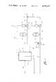
- FIG. 1 is a schematic representation of the first embodiment of the present invention.
- FIG. 2 is a schematic representation of a second embodiment of the present invention.
- the letter S designates generally the system of the present invention for conveying fluid from a single subsea supply conduit C to provide a fluid supply to two or more of a plurality of subsea control apparatus D, D', and D".
- the system S includes a fluid receiving means R which receives fluid under pressure from the single subsea supply conduit C.
- a charging means B charges two or more accumulator means A and A' independently of one another with fluid from the receiving means R, and, once charged, the accumulator means A and A' supply fluid to their associated control devices D and D'.
- FIG. 1 a first embodiment of the present invention
- a charging means B charges two or more accumulator means A and A' independently of one another with fluid from the receiving means R, and, once charged, the accumulator means A and A' supply fluid to their associated control devices D and D'.
- one of the control devices D" is an injection means I for injection fluid from the fluid receiving means into a subsea well flowline.
- a regulator means M is provided to control charging of accumulator means A and A' with fluid from the fluid receiving means R and to control fluid injection by the injection means I.
- the system S of the present invention is particularly adapted for use on or near a subsea wellhead.
- the subsea supply conduit C extends to the system S from a remote location, typically the ocean surface.
- the conduit C is attached to a source of pressurized fluid, and the conduit conveys this pressurized fluid from the source to the receiving means R of the system S.
- the receiving means R is any suitable, commercially available flowline, coupling, connection, or the like which may be suitably joined with the conduit C to form a fluid tight seal and which provides a fluid passageway for fluid communication between the system S and the single subsea supply conduit C.
- the receiving means R is in interruptible fluid communication with a first accumulator A through a flowline 12, a first accumulator valve 14, and a flowline 16.
- the first accumulator valve 14 is movable by means of an actuator 18 between an open position and a closed position. In its open position, valve 14 permits fluid flow between flowlines 12 and 16 so that fluid from the single subsea supply conduit C flows through the fluid receiving means R, flowline 12, valve 14, and flowline 16 to charge accumulator A with fluid from the single subsea supply conduit C. With valve 14 in its closed position, fluid flow between flowlines 12 and 16 is blocked by the valve so that the first accumulator A is isolated from flowline 12, receiving means R, and the single subsea supply conduit C.
- the second accumulator valve 24 is closed so that the fluid from the accumulator A' flows only in the direction of the control apparatus D'.
- the control valve 34 is opened, fluid flows from accumulator A' through line 30, valve 34, and line 38 to supply operating fluid to the in-line control valves. Accordingly, accumulator A' provides a source of operating fluid to the control apparatus D'.
- accumulator A provides a source of operating fluid through a flowline 44 to control apparatus D which is a part of an electro-hydraulic control pod 40.
- the electro-hydraulic control pod 40 is a conventional, commercially available ten function pod familiar to those having skill in the art.
- the control pod 40 has insulated electrical conductors 46 extending from it to a control panel located on the ocean surface. Control signals are transmitted to the electro-hydraulic control pod 40 by means of the conductor 46 to regulate hydraulic control signals and electrical control signals emitted from the control pod 40.
- the electro-hydraulic control pod 40 additionally serves as a portion of the charging means B for the system S.
- the charging means additionally includes the first accumulator valve 14, the second accumulator valve 24, and the actuators 18 and 28 associated with respective accumulator valves.
- the control pod 40 is provided with a hydraulic control line 50 which extends to the actuator 28 for opening and closing the second accumulator valve 24.
- operating fluid of the pod 40 is passed through the hydraulic signal line 50 to control the operation of actuator 28 and thereby control the opening and closing of valve 24.
- the electro-hydraulic control pod 40 is provided with an insulated conductor 52 which extends from the control pod 40 to actuator 18.
- an electrical control signal is transmitted from the pod 40 through conductor 52 to control the operation of actuator 18 and thereby control the opening and closing of the first accumulator valve 14.
- the actuator 28 Upon receipt of the control signal the actuator 28 opens the second accumulator valve 24 and thereby permits fluid to flow from the subsea supply conduit C, through the fluid receiving means R, flowline 22, valve 24, and flowline 26 to charge the accumulator A' with fluid from the supply conduit C.
- another control signal is conveyed to the pod 40 by conductor 46, and the hydraulic signal through line 50 is removed to cause actuator 28 to close the second accumulator valve 24.
- the accumulator A' is isolated from flowline 22 and the fluid receiving means R and accumulator A' serves as a fluid supply for the control apparatus D'.
- the charging means B charges the first accumulator A and the second accumulator A' independently of one another with fluid from the fluid receiving means R.
- the accumulators A and A' may be charged to different pressure levels.
- the single subsea supply conduit C operably connected to a source of pressurized fluid which alternately provides fluid at desired, different pressure levels
- the opening and closing of the accumulator valves 14 and 24 may be regulated so that the respective accumulators A and A' are charged with fluid at different pressure levels.
- the first accumulator A receives fluid at a first pressure level from the fluid receiving means R and is thereby charged with fluid at that first pressure level.
- Another control signal is then conveyed to pod 40 through conductor 46, causing a control signal to be transmitted to actuator 18 over conductor 52 to close the first accumulator valve 14 and thereby isolate the first accumulator A from the fluid receiving means R.
- the source of pressurized fluid is then regulated to provide fluid through the supply conduit C at a second pressure level.
- a suitable control signal is next conveyed to control pod 40 by conduit 46 to cause a hydraulic signal to be conveyed by line 50 to actuator 28, causing the actuator 28 to open the second accumulator valve 24.
- the second accumulator A' is thus placed in fluid communication with the fluid receiving means R and is charged with fluid at the second pressure level. After the charging of the second accumulator A' has been completed, an additional control signal is conveyed to control pod 40 over conductor 46 to cause a different control signal to be transmitted to actuator 28 by flowline 50 and to close the second accumulator valve 24.
- both accumulators are isolated from one another and have been charged with fluid at different pressure levels to provide appropriate fluid supplies to their respective well control devices D and D'.
- FIG. 2 The second embodiment of the present invention is schematically illustrated in FIG. 2.
- Many of the elements shown in FIG. 3 are substantially identical in structure and perform the same functions performed by corresponding elements previously described herein with reference to the first embodiment of the present invention. Accordingly, like letters and numerals are used in FIGS. 1 and 2 to designate like elements.
- the second embodiment of the present invention is a system for conveying fluid from the single subsea supply conduit C to provide a fluid supply for both subsea well valve control apparatus and fluid injection apparatus.
- the fluid receiving means R is in fluid communication with flowlines 58 and 60.
- the flowline 58 is operably connected to a first feeder conduit 62 so that a fluid passageway is provided between the fluid receiving means R and the first accumulator valve 14.
- a second feeder conduit 64 is connected to the flowline 58 to place the fluid receiving means R in fluid communication with the second accumulator valve 24.
- the flowline 60 maintains the fluid receiving means R in fluid communication with an injection valve 66 which is movable between open and closed positions by an actuator 68. With the valve 66 in its open position, the valve passes fluid between the flowline 60 and an injection line 70. With the valve 66 in its closed position, the valve blocks fluid flow between the flowline 60 and the injection line 70.
- the injection line 70 is a part of the fluid injection means I for injecting a fluid into a subsea well flowline 72.
- the injection line 70 may be provided with a check valve 74 to ensure that fluid in line 70 flows only from the injection valve 66 toward the well flowline 72.
- the injection line 70 is provided to convey a freezing retardant fluid into the well flowline 72 when the injection valve 66 is open. Once injected into the well flowline 72, the freezing retardant fluid retards or eliminates the freezing of fluids in the well flowline.
- the subsea supply conduit C conveys such a freezing retardant fluid to the fluid receiving means R.
- the freezing retardant fluid is glycol or methanol, but other suitable freezing retardant fluids may be utilized.
- the freezing retardant fluid supplied by the single subsea supply conduit C through the fluid receiving means R not only serves as the injection fluid which is injected into the well flowline 72, but also serves as the fluid medium for charging both the first accumulator A and the second accumulator A'.
- a suitable source of fluid is provided by the system S for injecting fluid into the well flowline 72 and for providing fluid supplies for the subsea well valve control apparatus.
- the regulating means M controls injection of fluid by the injection means I and controls the charging of the accumulators A and A'.
- the regulating means M includes a portion of control pod 40, accumulator valves 14 and 24, injection valve 66, and the associated actuators 18, 28, and 68.
- the injection valve 66 and the accumulator valves 14 and 24 are initially in their closed positions.
- An electrical control signal is supplied to the electro-hydraulic control pod 40 by conductor 46 to cause an electrical control signal to be conveyed by conductor 52 to the actuator 18 to open the first accumulator valve 14.
- first accumulator valve With the first accumulator valve in its open position, fluid flows from the supply conduit C through the receiving means R, flowline 58, feeder conduit 62, valve 14, and line 16 to charge the first accumulator A with fluid. Subsequent to the charging of the first accumulator A, a second control signal is transmitted to the electro-hydraulic control pod 40 by conductor 46 to cause a different control signal to be transmitted to actuator 18 by conductor 52 so that the first accumulator valve 14 is closed. With the closing of the first accumulator valve 14 subsequent to the charging of the first accumulator A, the electro-hydraulic control pod 40 is provided with a source of operating fluid from the accumulator A through flowline 44.
- Another control signal is then conveyed to the control pod 40 by conductor 46 to cause a hydraulic pressure signal to be conveyed to actuator 28 through the actuator signal conduit 50.
- This signal causes the actuator 28 to open the second accumulator valve 24.
- the second accumulator valve 24 With the second accumulator valve 24 is its open position, fluid flows from the subsea supply conduit C through the fluid receiving means R, flowline 58, feeder conduit 64, valve 24, and line 26 to charge the second accumulator A' with fluid from the single subsea supply conduit.
- another control signal is conveyed to the control pod by conductor 46, causing a different hydraulic control signal to be conveyed to actuator 28 through conduit 50.
- This latter hydraulic control signal causes the actuator 28 to close the second accumulator valve 24.
- both the first accumulator A and the second accumulator A' are charged with fluid and provide a fluid supply to the control pod 40 and the control apparatus D', respectively.
- the injection valve 66 may now be opened as desired to inject fluid from the single subsea supply conduit C into the well flowline 72 to prevent freezing in the latter flowline.
- a hydraulic signal conveying conduit 78 extends between the control pod 40 and the actuator 68 to permit control of the opening and closing of the injection valve 66.
- a hydraulic pressure is exerted through the conduit 78 to the actuator 68 to cause the injection valve 66 to open.
- fluid is conveyed from the single subsea supply conduit C, through the fluid receiving means R, flowline 60, injection valve 66, and injection line 70 into the well control flowline 72.
- fluid is conveyed from the single subsea supply conduit C to provide a fluid supply for both the well valve control apparatus and the injection apparatus I.
- accumulators A and A' may be charged to different pressure levels and injection of fluid into well flowline 72 may be accomplished at yet a different pressure level.
- the single subsea supply conduit C is connected to pressurized fluid source which alternatively supplies fluid at three pressure levels
- the opening and closing of valves 14, 24, and 66 may be regulated by appropriate signals to the control pod 40 to open the respective valves individually and at times when an appropriate pressure level is present in the fluid supply through the single supply conduit C.
- each of the valves described herein have a failsafe closed construction. In this manner, leakage of fluid from either the system S or the control apparatus is reduced or eliminated in the event of a break in the associated flowlines or conduits.
Landscapes
- Life Sciences & Earth Sciences (AREA)
- Engineering & Computer Science (AREA)
- Geology (AREA)
- Mining & Mineral Resources (AREA)
- Physics & Mathematics (AREA)
- Environmental & Geological Engineering (AREA)
- Fluid Mechanics (AREA)
- General Life Sciences & Earth Sciences (AREA)
- Geochemistry & Mineralogy (AREA)
- Fluid-Pressure Circuits (AREA)
Abstract
Description
Claims (14)
Priority Applications (1)
| Application Number | Priority Date | Filing Date | Title |
|---|---|---|---|
| US05/667,175 US4036247A (en) | 1976-03-15 | 1976-03-15 | Multi-pressure, single line supply system |
Applications Claiming Priority (1)
| Application Number | Priority Date | Filing Date | Title |
|---|---|---|---|
| US05/667,175 US4036247A (en) | 1976-03-15 | 1976-03-15 | Multi-pressure, single line supply system |
Publications (1)
| Publication Number | Publication Date |
|---|---|
| US4036247A true US4036247A (en) | 1977-07-19 |
Family
ID=24677126
Family Applications (1)
| Application Number | Title | Priority Date | Filing Date |
|---|---|---|---|
| US05/667,175 Expired - Lifetime US4036247A (en) | 1976-03-15 | 1976-03-15 | Multi-pressure, single line supply system |
Country Status (1)
| Country | Link |
|---|---|
| US (1) | US4036247A (en) |
Cited By (15)
| Publication number | Priority date | Publication date | Assignee | Title |
|---|---|---|---|---|
| FR2431085A2 (en) * | 1978-07-12 | 1980-02-08 | Gratzmuller J | Valve for undersea petroleum wells - is operated by hydraulic energy stored at well-head on instructions transmitted hydraulically through small-bore pipe, minimising cost |
| EP0023012A2 (en) * | 1979-07-21 | 1981-01-28 | Fmc Corporation | Apparatus for the remote control of oil or gas wells |
| WO1983002798A1 (en) * | 1982-02-05 | 1983-08-18 | Andre Galerne | System for activating a blowout preventer |
| US4640310A (en) * | 1984-12-26 | 1987-02-03 | Nordson Corporation | Variable air-piloted air regulator system |
| US5076767A (en) * | 1989-12-18 | 1991-12-31 | Master Flo Technology Inc. | Liquid flow metering |
| US5438714A (en) * | 1989-10-31 | 1995-08-08 | Bauer Industries, Inc. | Fresh water manifold distribution system and method |
| WO1999063234A2 (en) * | 1998-06-05 | 1999-12-09 | Bengt Gunnarsson | A device and method for regulating fluid flow in a well |
| WO2001038694A1 (en) * | 1999-11-24 | 2001-05-31 | Navion Asa | Method and system for preventing hydrate formation by reinjecting hydrocarbon gas including methanol |
| US6247536B1 (en) | 1998-07-14 | 2001-06-19 | Camco International Inc. | Downhole multiplexer and related methods |
| GB2396662A (en) * | 2002-12-23 | 2004-06-30 | Bakke Oil Tools As | Method and device for pressure controlled sequential operation |
| US20050087344A1 (en) * | 2003-10-24 | 2005-04-28 | Schlumberger Technology Corporation | System and Method to Control Multiple Tools Through One Control Line |
| US20080223467A1 (en) * | 2007-03-16 | 2008-09-18 | Fmc Kongsberg Subsea As | Method and device for regulating a pressure in a hydraulic system |
| US20120111572A1 (en) * | 2010-11-09 | 2012-05-10 | Cargol Jr Patrick Michael | Emergency control system for subsea blowout preventer |
| US8281897B1 (en) * | 2010-02-02 | 2012-10-09 | Trendsetter Engineering, Inc. | Automatic accumulator switching apparatus and system |
| US12091929B2 (en) | 2022-09-19 | 2024-09-17 | Trendsetter Engineering, Inc. | Subsea grease injection system |
Citations (2)
| Publication number | Priority date | Publication date | Assignee | Title |
|---|---|---|---|---|
| US3718316A (en) * | 1970-09-04 | 1973-02-27 | Vetco Offshore Ind Inc | Hydraulic-pneumatic weight control and compensating apparatus |
| US3993100A (en) * | 1974-04-29 | 1976-11-23 | Stewart & Stevenson Oiltools, Inc. | Hydraulic control system for controlling a plurality of underwater devices |
-
1976
- 1976-03-15 US US05/667,175 patent/US4036247A/en not_active Expired - Lifetime
Patent Citations (2)
| Publication number | Priority date | Publication date | Assignee | Title |
|---|---|---|---|---|
| US3718316A (en) * | 1970-09-04 | 1973-02-27 | Vetco Offshore Ind Inc | Hydraulic-pneumatic weight control and compensating apparatus |
| US3993100A (en) * | 1974-04-29 | 1976-11-23 | Stewart & Stevenson Oiltools, Inc. | Hydraulic control system for controlling a plurality of underwater devices |
Cited By (25)
| Publication number | Priority date | Publication date | Assignee | Title |
|---|---|---|---|---|
| FR2431085A2 (en) * | 1978-07-12 | 1980-02-08 | Gratzmuller J | Valve for undersea petroleum wells - is operated by hydraulic energy stored at well-head on instructions transmitted hydraulically through small-bore pipe, minimising cost |
| EP0023012A2 (en) * | 1979-07-21 | 1981-01-28 | Fmc Corporation | Apparatus for the remote control of oil or gas wells |
| EP0023012A3 (en) * | 1979-07-21 | 1981-05-06 | Fmc Corporation | Control systems and control method for oil or gas wells |
| WO1983002798A1 (en) * | 1982-02-05 | 1983-08-18 | Andre Galerne | System for activating a blowout preventer |
| US4640310A (en) * | 1984-12-26 | 1987-02-03 | Nordson Corporation | Variable air-piloted air regulator system |
| US5438714A (en) * | 1989-10-31 | 1995-08-08 | Bauer Industries, Inc. | Fresh water manifold distribution system and method |
| US5076767A (en) * | 1989-12-18 | 1991-12-31 | Master Flo Technology Inc. | Liquid flow metering |
| US6516888B1 (en) | 1998-06-05 | 2003-02-11 | Triangle Equipment As | Device and method for regulating fluid flow in a well |
| WO1999063234A2 (en) * | 1998-06-05 | 1999-12-09 | Bengt Gunnarsson | A device and method for regulating fluid flow in a well |
| CN1118613C (en) * | 1998-06-05 | 2003-08-20 | 特里安格尔设备公司 | Device and method for regulating fluid flow in well |
| WO1999063234A3 (en) * | 1998-06-05 | 2000-03-09 | Bengt Gunnarsson | A device and method for regulating fluid flow in a well |
| US6247536B1 (en) | 1998-07-14 | 2001-06-19 | Camco International Inc. | Downhole multiplexer and related methods |
| WO2001038694A1 (en) * | 1999-11-24 | 2001-05-31 | Navion Asa | Method and system for preventing hydrate formation by reinjecting hydrocarbon gas including methanol |
| GB2374364A (en) * | 1999-11-24 | 2002-10-16 | Navion Asa | Method and system for preventing hydrate formation by reinjecting hydrocarbon gas including methanaol |
| US7264059B2 (en) | 2002-12-23 | 2007-09-04 | Bakke Oil Tools, As | Method and device for pressure controlled sequential operation |
| GB2396662A (en) * | 2002-12-23 | 2004-06-30 | Bakke Oil Tools As | Method and device for pressure controlled sequential operation |
| US20040149448A1 (en) * | 2002-12-23 | 2004-08-05 | Frank Akselberg | Method and device for pressure controlled sequential operation |
| GB2396662B (en) * | 2002-12-23 | 2006-02-22 | Bakke Oil Tools As | Method and device for pressure controlled sequential operation |
| US20050087344A1 (en) * | 2003-10-24 | 2005-04-28 | Schlumberger Technology Corporation | System and Method to Control Multiple Tools Through One Control Line |
| US7306043B2 (en) | 2003-10-24 | 2007-12-11 | Schlumberger Technology Corporation | System and method to control multiple tools through one control line |
| US20080223467A1 (en) * | 2007-03-16 | 2008-09-18 | Fmc Kongsberg Subsea As | Method and device for regulating a pressure in a hydraulic system |
| US8156953B2 (en) * | 2007-03-16 | 2012-04-17 | Fmc Kongsberg Subsea As | Method and device for regulating a pressure in a hydraulic system |
| US8281897B1 (en) * | 2010-02-02 | 2012-10-09 | Trendsetter Engineering, Inc. | Automatic accumulator switching apparatus and system |
| US20120111572A1 (en) * | 2010-11-09 | 2012-05-10 | Cargol Jr Patrick Michael | Emergency control system for subsea blowout preventer |
| US12091929B2 (en) | 2022-09-19 | 2024-09-17 | Trendsetter Engineering, Inc. | Subsea grease injection system |
Similar Documents
| Publication | Publication Date | Title |
|---|---|---|
| US4036247A (en) | Multi-pressure, single line supply system | |
| US8156953B2 (en) | Method and device for regulating a pressure in a hydraulic system | |
| US3894560A (en) | Subsea control network | |
| US6484806B2 (en) | Methods and apparatus for hydraulic and electro-hydraulic control of subsea blowout preventor systems | |
| US8820410B2 (en) | Control system for blowout preventer stack | |
| US4095421A (en) | Subsea energy power supply | |
| JPH0134961Y2 (en) | ||
| US4467833A (en) | Control valve and electrical and hydraulic control system | |
| US20230366292A1 (en) | Full bore electric flow control valve system | |
| AU734396B2 (en) | Fail-safe closure system for remotely operable valve actuator | |
| EP3702580B1 (en) | Manifolds for providing hydraulic fluid to a subsea blowout preventer and related methods | |
| US20030145994A1 (en) | Device for installation and flow test of subsea completions | |
| US8181704B2 (en) | Riser emergency disconnect control system | |
| EP1444415B1 (en) | Single well development system | |
| US20090218096A1 (en) | Control System for an Annulus Balanced Subsurface Safety Valve | |
| WO2008134266B1 (en) | Subsea well control system and method | |
| MXPA02008578A (en) | Electro hydraulically pressurized downhole valve actuator. | |
| GB2335216A (en) | Extraction of fluid from wells | |
| US20130056222A1 (en) | Multiple Control Line Assembly for Downhole Equipment | |
| EP0527619B1 (en) | Wet christmas tree | |
| WO2015104173A2 (en) | Electrical wellhead shutdown system | |
| US11091971B2 (en) | Modular electro-hydraulic downhole control system | |
| WO1999047788A1 (en) | Well control | |
| US11047208B2 (en) | Chemical injection system | |
| US5172767A (en) | Water spray control system for underground mining machine |
Legal Events
| Date | Code | Title | Description |
|---|---|---|---|
| AS | Assignment |
Owner name: VETCO OFFSHORE, INC. 5740 RALSTON ST.VENTURA,CA.93 Free format text: ASSIGNMENT OF ASSIGNORS INTEREST.;ASSIGNOR:VETCO INC.;REEL/FRAME:004056/0858 Effective date: 19820922 |
|
| AS | Assignment |
Owner name: VETCO OFFSHORE INDUSTRIES, INC., 7135 ARDMORE ROAD Free format text: ASSIGNMENT OF ASSIGNORS INTEREST.;ASSIGNOR:VETCO OFFSHORE, INC., A CORP. OF DE.;REEL/FRAME:004572/0533 Effective date: 19860421 |
|
| AS | Assignment |
Owner name: VETCO GRAY INC., Free format text: MERGER;ASSIGNORS:GRAY TOOL COMPANY, A TX. CORP. (INTO);VETCO OFFSHORE INDUSTRIES, INC., A CORP. (CHANGED TO);REEL/FRAME:004748/0332 Effective date: 19861217 |
|
| AS | Assignment |
Owner name: CITIBANK, N.A., AS AGENT Free format text: SECURITY INTEREST;ASSIGNOR:VETCO GRAY INC.;REEL/FRAME:005211/0237 Effective date: 19891128 |