US396121A - Thermo-Magnetic Motor - Google Patents
Thermo-Magnetic Motor Download PDFInfo
- Publication number
- US396121A US396121A US396121DA US396121A US 396121 A US396121 A US 396121A US 396121D A US396121D A US 396121DA US 396121 A US396121 A US 396121A
- Authority
- US
- United States
- Prior art keywords
- armature
- heat
- magnet
- thermo
- magnetism
- Prior art date
- Legal status (The legal status is an assumption and is not a legal conclusion. Google has not performed a legal analysis and makes no representation as to the accuracy of the status listed.)
- Expired - Lifetime
Links
- 230000005389 magnetism Effects 0.000 description 10
- 238000001816 cooling Methods 0.000 description 2
- 238000010586 diagram Methods 0.000 description 2
- 230000003292 diminished effect Effects 0.000 description 2
- 238000010276 construction Methods 0.000 description 1
- 238000010438 heat treatment Methods 0.000 description 1
- 230000006698 induction Effects 0.000 description 1
- 230000001105 regulatory effect Effects 0.000 description 1
Images

Classifications
-
- H—ELECTRICITY
- H01—ELECTRIC ELEMENTS
- H01J—ELECTRIC DISCHARGE TUBES OR DISCHARGE LAMPS
- H01J45/00—Discharge tubes functioning as thermionic generators
Definitions
- NIKOLA 'rEsLA or SMILJAN, LIKA, AUSTRIA-HUNGARY.
- I am able to make use of either an electro-magnet ora permanent magnet, and I preferably direct the ismagnetized by in duction, rather than directly against a perma nentnn gnet, thereby avoiding the loss of magnetism that might result in the permanent magnet by the action of heat. I also provide for lessening the Volume of the heat or for intercepting the same during that portion of the reciprocation in which the cooling action takes place.
- Fig. 2 represents the same parts as before described; but an electro-magnet is illustrated in place of a permanent magnet. The operations, however, are the same.
- Fig. 3 I have shown the same parts as in Figs. '1 and 2, only they are differently arranged.
- the armature A instead of swinging, is stationary and held by an arm, I", and the core N S of the electro-magnet is made to swing within the helix.
- Q the said eore being suspended by the arm P from the pivot M.
- a shield, R is connected with the magnet-core and swings therewith, so that-after the heat has demagnetized the arimtture A to such an extent that the spring Vi draws the core N S away from thearmature A the shield R comes between the flame ll and armature A, thereby intercepting the action of the'heat and allowing the armature to cool, so that the limit myself in this magnetism, again preponderating, causes the movement of the core N S toward the armature A and the removal of the shield R from above the flame, so that the heat again acts to lesson or neutralize the magnetism.
- a rotary or other movement may be obtained from this reciprocation.
- Fig. 4 corresponds in every respect with Fig. 3, except that a permanent horseshoemagnet, N S, is represented as taking the place of the eleetro-magnet in said Fig. 3.
- a helix, Q with an armature adapted to swing toward or from will be .made use of, as indicated the helix.
- the armature may assume the form of a solenoid-core, there being nopermauent core within the helix.
- Fig. 6 is an endview
- Fig. 7 a plan view, illustrating my improvmnent as applied to a swinging arinaturc,1 ⁇ , and a stationary permanent magnet, N h.
- I apply the heat to an auxiliary armature or keeper, '1, which is adjaeentioand preferably in direct contact with the magnet.
- This armature '1 in the form oi? a plate of sheetiron, extends across from one pole to the other I and is of sufficient sectionjopractically form a keeper for the magnet, so that when this armature '1 is cool nearly allthe lines of force pass over the same and ver little free magnetism is exhibited.
- Fig. 8 I have shown a permanent magnet and keeper-plate, 'l, similar to those in. Figs. 6 and 7, with the burners H for the gas beneath the same; but the I 39 BEST AVAlLABLE CO1 armature is pivoted at one end to one pole of the magnet and the other end swings toward and from the other pole of the magnet.
- the apring W acts against a lever-arm that projeets from the armature, and the supply of heat has to be partly cut off by a connection to the swinging armature, so as to lessen the heat acting upon the keeper-plate when the armature A has been attracted.
- Fig. 9 is similar in Fig. 8, except that the keep(.*r"l is not made use of and the armature itself swings into and out of the range of the intense action of the heat from the burner li.
- Fig. 10 is a diagram similar to Fig. .1, except that in place of using a spring and stops the armature is shown as connected byalink, 12, to the crank 13 of a fly-wheel, so that the flywheel will be revolved as rapidly as the armature can be heated and cooled to the necessary extent.
- a spring may be used in addition, as in Fig. l.
- the twoarmaturcs A A are eounect'ed by a link, so that one will be heating while the other is cooling, and the attraction exerted to move the cooled armature is availed of to draw away the heated armature instead of using a spring.
Landscapes
- Hard Magnetic Materials (AREA)
Description
(N0 Made BEST AVAILABLE COP N. TESLA.
THERMO MAGNETIC MOTOR.
No. 396,121. Patented Jan.15,1889.
2 Sheets-Sheet 1.
BEST AvAxLABLE GOP (NoModeL) 2 SheetsSheet 2.
N. TESLA.
THERMO MAGNETIC MOTOR.
No. 396,121 Patented Jan. 15, 1889.
' stored to move the body heat against a body that BEST AvAiLAsLE cc? UNITED STATES.-
PATENT OFFICE.
NIKOLA 'rEsLA, or SMILJAN, LIKA, AUSTRIA-HUNGARY.
THERMO-MAGNETIC MOTOR.
. SPECIFICATION forming part-of Letters retentive. 396,121, dated January 1-5, 1889. Application filed March so, 1886. Serial no. 197,115; (No model.)
To all whom it may concern.-
Be it known that I, NIKOLA 'IESLA, of. Smiljan, Lika, Border Country of Austria-Hungary, have invented an Improvement in ThermoMagnetic Motors, of which the following is a specification.
It is well known that heat applied to a magnetized body will lessen the magnetism, and if the temperature is raised sufficientl y the magnetism will be neutralized or destroyed.
In my present invention I obtain mechanical power by a reciprocating action resulting from the joint operations of heat, magnetism, and a spring or weight or other foreethat is to say, I subject a body magnetized by induction or otherwise tot-he action of heat until the magnetism is sufiiciently neutralized to allow a weight or spring to give motion to the body and lessen the action of the heat, so vthat the magnetism may be sufiiciently rein the opposite direction, and again subject the same to thedemagnetizing of the heat.
In carrying out my invention I am able to make use of either an electro-magnet ora permanent magnet, and I preferably direct the ismagnetized by in duction, rather than directly against a perma nentnn gnet, thereby avoiding the loss of magnetism that might result in the permanent magnet by the action of heat. I also provide for lessening the Volume of the heat or for intercepting the same during that portion of the reciprocation in which the cooling action takes place.
In the drawings I have rcpresentml by diagrams some of the numerous arrangements that may be made use of in carrying out my invention. In all of these figures the magnctspoles are marked N S, the armatnre A, the ,Bnnsen burner or other source of heat II, the axisot' motion M, and the springer the equivalent theroofnamely, a weightis marked W.
In Figure 1 the permanent magnet N is eonnected with a frame, F, supporting the axis M, from which the arm-P h. ngs, and at the lower end of which the armature A is supported. The stops 2 and 3 limit the extent of motion, and the spring \V tends to draw the armatureA away from the magnet N. It is now to be understood that the magnetism wheel shaft attraction of the magnet N overcomes the spring \V and draws the armature A back again above theliinrner lI, so that thesalne is again heated and v the, operations are repeated. The reciprocating mvements thus obtained are employed as a source of mechanical power in any desired manner. Usually a eonnectingrod: to a crank upon a flyin Fig. 10; but I do not respect. a
Fig. 2 represents the same parts as before described; but an electro-magnet is illustrated in place of a permanent magnet. The operations, however, are the same.
In Fig. 3 I have shown the same parts as in Figs. '1 and 2, only they are differently arranged. The armature A, instead of swinging, is stationary and held by an arm, I", and the core N S of the electro-magnet is made to swing within the helix. Q, the said eore being suspended by the arm P from the pivot M. A shield, R, is connected with the magnet-core and swings therewith, so that-after the heat has demagnetized the arimtture A to such an extent that the spring Vi draws the core N S away from thearmature A the shield R comes between the flame ll and armature A, thereby intercepting the action of the'heat and allowing the armature to cool, so that the limit myself in this magnetism, again preponderating, causes the movement of the core N S toward the armature A and the removal of the shield R from above the flame, so that the heat again acts to lesson or neutralize the magnetism. A rotary or other movement may be obtained from this reciprocation. Fig. 4 corresponds in every respect with Fig. 3, except that a permanent horseshoemagnet, N S, is represented as taking the place of the eleetro-magnet in said Fig. 3.
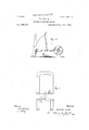
In Fig. 5 I have shown a helix, Q, with an armature adapted to swing toward or from will be .made use of, as indicated the helix. In this case there may be a softiron core in the helix, or the armature may assume the form of a solenoid-core, there being nopermauent core within the helix.
= Fig. 6 is an endview, and Fig. 7 a plan view, illustrating my improvmnent as applied to a swinging arinaturc,1\, and a stationary permanent magnet, N h. in this instance I apply the heat to an auxiliary armature or keeper, '1, which is adjaeentioand preferably in direct contact with the magnet. This armature '1, in the form oi? a plate of sheetiron, extends across from one pole to the other I and is of sufficient sectionjopractically form a keeper for the magnet, so that when this armature '1 is cool nearly allthe lines of force pass over the same and ver little free magnetism is exhibited. Then the armature A, which swings freely on the pivots M in front of the poles N h, is very little attracted and the spring s pulls the same away from the poles into the position ii'ulicated in the drawings. The heat is di reeted upon the i ron plate 'I at some distance from the magnet, so
as to allow the magnet to he kept (5()lll]')1tIlt-.
tively cool. 'lhis heat is applied beneath the plate by means of the burners H, and there is a connection from the armatureA or itspivot to the gas-cock 6 or other device for regulating the heat. The heat acting upon the m ido' dle portion of the plate '1, the magnetic conduetivity of the heated portion is diminished or destroyed, anda great number of the lines of force.v are deflected over, the ,armature A,
which is now powerfully attracted and drawn into line, ornearly so, with the poles N S. In so doing the cock 6 is nearly closed and the plate '1 cools, the lines of force are again defleeted over the same, the attraction exerted upon the armature A is diminished, and the spring W pulls the same away from the magnet into the position shown by full lines, and the operations are repeated. The arrangement shown in l ig. 6 has the advantages that the magnet and armature are kept cool and the strength of the permanent magnet'is better preserved, as the magnetic circuit is constantly closed.
In the plan view, Fig. 8, I have shown a permanent magnet and keeper-plate, 'l, similar to those in. Figs. 6 and 7, with the burners H for the gas beneath the same; but the I 39 BEST AVAlLABLE CO1 armature is pivoted at one end to one pole of the magnet and the other end swings toward and from the other pole of the magnet. The apring W acts against a lever-arm that projeets from the armature, and the supply of heat has to be partly cut off by a connection to the swinging armature, so as to lessen the heat acting upon the keeper-plate when the armature A has been attracted.
Fig. 9 is similar in Fig. 8, except that the keep(.*r"l is not made use of and the armature itself swings into and out of the range of the intense action of the heat from the burner li.
Fig. 10 is a diagram similar to Fig. .1, except that in place of using a spring and stops the armature is shown as connected byalink, 12, to the crank 13 of a fly-wheel, so that the flywheel will be revolved as rapidly as the armature can be heated and cooled to the necessary extent. A spring may be used in addition, as in Fig. l.
'In Fig. '1 ly the twoarmaturcs A A are eounect'ed by a link, so that one will be heating while the other is cooling, and the attraction exerted to move the cooled armature is availed of to draw away the heated armature instead of using a spring.
I have shown in the drawings several ways of carrying out my invention; but said invention is not limited by any particular form, arrangement, or construction of devices.
I claim as my invention- 1. The combination, with a swinging body undertheinfiuenee of magneiism,of a burner or other source of heat acting to vary the
Publications (1)
| Publication Number | Publication Date |
|---|---|
| US396121A true US396121A (en) | 1889-01-15 |
Family
ID=2465091
Family Applications (1)
| Application Number | Title | Priority Date | Filing Date |
|---|---|---|---|
| US396121D Expired - Lifetime US396121A (en) | Thermo-Magnetic Motor |
Country Status (1)
| Country | Link |
|---|---|
| US (1) | US396121A (en) |
Cited By (16)
| Publication number | Priority date | Publication date | Assignee | Title |
|---|---|---|---|---|
| US3213208A (en) * | 1961-08-14 | 1965-10-19 | Tung Sol Electric Inc | Electric to sonic transducer |
| US3445740A (en) * | 1968-02-20 | 1969-05-20 | Merkl George | Step-by-step thermo-magnetic motor |
| US5714829A (en) * | 1995-01-10 | 1998-02-03 | Guruprasad; Venkata | Electromagnetic heat engines and method for cooling a system having predictable bursts of heat dissipation |
| US20050062360A1 (en) * | 2003-09-08 | 2005-03-24 | Canon Kabushiki Kaisha | Thermal engine and thermal power generator both using magnetic body |
| US20060045755A1 (en) * | 2004-08-24 | 2006-03-02 | Dell Products L.P. | Information handling system including AC electromagnetic pump cooling apparatus |
| US20060266041A1 (en) * | 2005-05-24 | 2006-11-30 | Fellows Oscar L | Thermoacoustic Thermomagnetic Generator |
| US20100253181A1 (en) * | 2009-04-06 | 2010-10-07 | John Hazelwood | Special Thermo Magnetic Motor Device |
| AU2005205732B2 (en) * | 2004-08-31 | 2011-01-27 | Terry William Robinson | Thermo-magnetic engine |
| US20110048032A1 (en) * | 2009-08-31 | 2011-03-03 | Delta Electronics, Inc. | Heat-power conversion magnetism device and system for converting energy thereby |
| US20110062821A1 (en) * | 2009-09-17 | 2011-03-17 | Chang Shao Hsiung | Heat-power conversion magnetism devices |
| US8984885B2 (en) | 2012-04-09 | 2015-03-24 | Delta Electronics, Inc. | Thermal magnetic engine and thermal magnetic engine system |
| DE202017001688U1 (en) | 2017-03-23 | 2017-04-21 | Matthias Neumann | Curie shuttle |
| ES2639624R1 (en) * | 2016-04-27 | 2018-02-19 | Javier Jerez Fernandez | THERMOMAGNETIC MOTOR |
| IT201800010096A1 (en) | 2018-11-07 | 2020-05-07 | Fondazione St Italiano Tecnologia | Thermomagnetic apparatus for the generation of electric current and related method |
| DE102020118370B3 (en) | 2020-07-13 | 2021-11-04 | Leibniz-Institut für Festkörper- und Werkstoffforschung Dresden e.V. (IFW Dresden e.V.) | Device and method for converting thermal energy into electrical energy |
| DE102021111085B3 (en) | 2021-04-29 | 2022-10-06 | Leibniz-Institut für Festkörper- und Werkstoffforschung Dresden e.V. (IFW Dresden e.V.) | Device and method for converting thermal energy into mechanical energy |
-
0
- US US396121D patent/US396121A/en not_active Expired - Lifetime
Cited By (21)
| Publication number | Priority date | Publication date | Assignee | Title |
|---|---|---|---|---|
| US3213208A (en) * | 1961-08-14 | 1965-10-19 | Tung Sol Electric Inc | Electric to sonic transducer |
| US3445740A (en) * | 1968-02-20 | 1969-05-20 | Merkl George | Step-by-step thermo-magnetic motor |
| US5714829A (en) * | 1995-01-10 | 1998-02-03 | Guruprasad; Venkata | Electromagnetic heat engines and method for cooling a system having predictable bursts of heat dissipation |
| US20050062360A1 (en) * | 2003-09-08 | 2005-03-24 | Canon Kabushiki Kaisha | Thermal engine and thermal power generator both using magnetic body |
| US20060045755A1 (en) * | 2004-08-24 | 2006-03-02 | Dell Products L.P. | Information handling system including AC electromagnetic pump cooling apparatus |
| AU2005205732B2 (en) * | 2004-08-31 | 2011-01-27 | Terry William Robinson | Thermo-magnetic engine |
| US20060266041A1 (en) * | 2005-05-24 | 2006-11-30 | Fellows Oscar L | Thermoacoustic Thermomagnetic Generator |
| US20070175217A1 (en) * | 2005-05-24 | 2007-08-02 | Fellows Oscar L | Thermoacoustic thermomagnetic generator |
| US20100253181A1 (en) * | 2009-04-06 | 2010-10-07 | John Hazelwood | Special Thermo Magnetic Motor Device |
| US8242662B2 (en) | 2009-04-06 | 2012-08-14 | John Hazelwood | Special thermo magnetic motor device |
| US8453466B2 (en) | 2009-08-31 | 2013-06-04 | Delta Electronics, Inc. | Heat-power conversion magnetism device and system for converting energy thereby |
| US20110048032A1 (en) * | 2009-08-31 | 2011-03-03 | Delta Electronics, Inc. | Heat-power conversion magnetism device and system for converting energy thereby |
| US20110062821A1 (en) * | 2009-09-17 | 2011-03-17 | Chang Shao Hsiung | Heat-power conversion magnetism devices |
| US8646280B2 (en) * | 2009-09-17 | 2014-02-11 | Delta Electronics, Inc. | Heat-power conversion magnetism devices |
| US8984885B2 (en) | 2012-04-09 | 2015-03-24 | Delta Electronics, Inc. | Thermal magnetic engine and thermal magnetic engine system |
| ES2639624R1 (en) * | 2016-04-27 | 2018-02-19 | Javier Jerez Fernandez | THERMOMAGNETIC MOTOR |
| DE202017001688U1 (en) | 2017-03-23 | 2017-04-21 | Matthias Neumann | Curie shuttle |
| IT201800010096A1 (en) | 2018-11-07 | 2020-05-07 | Fondazione St Italiano Tecnologia | Thermomagnetic apparatus for the generation of electric current and related method |
| US11682959B2 (en) | 2018-11-07 | 2023-06-20 | Fondazione Istituto Italiano Di Tecnologia | Thermomagnetic apparatus for electric power generation and method thereof |
| DE102020118370B3 (en) | 2020-07-13 | 2021-11-04 | Leibniz-Institut für Festkörper- und Werkstoffforschung Dresden e.V. (IFW Dresden e.V.) | Device and method for converting thermal energy into electrical energy |
| DE102021111085B3 (en) | 2021-04-29 | 2022-10-06 | Leibniz-Institut für Festkörper- und Werkstoffforschung Dresden e.V. (IFW Dresden e.V.) | Device and method for converting thermal energy into mechanical energy |
Similar Documents
| Publication | Publication Date | Title |
|---|---|---|
| US396121A (en) | Thermo-Magnetic Motor | |
| US2895063A (en) | Air driven reed electric generator | |
| US3014116A (en) | Magnetic heater | |
| US822323A (en) | Thermostatic control. | |
| US1839165A (en) | Thermo-magnetically operated device | |
| US2794090A (en) | Electromagnetic switch relays | |
| US1312692A (en) | Motion-transmitting apparatus | |
| US226485A (en) | Jesse h | |
| GB578611A (en) | An improved thermally operated electric switching device | |
| US3582695A (en) | Mechanically toggled electrical pulse generator | |
| US808957A (en) | Circuit-controller. | |
| US1013494A (en) | Electromotor. | |
| US1743470A (en) | Magnetic device | |
| US764518A (en) | Electrical heat-motor. | |
| US560652A (en) | Electromagnetic motor | |
| US344679A (en) | eecordon | |
| US938501A (en) | Adding machine. | |
| US190206A (en) | Improvement in electro-magnetic | |
| US1550180A (en) | Electromagnetic operating mechanism | |
| US946487A (en) | Electromagnet. | |
| US737553A (en) | Electric motor. | |
| GB603961A (en) | Improvements in the shutter operating devices of photographic cameras | |
| US571952A (en) | Electric switch | |
| US473960A (en) | Electric clock-motor | |
| US1325257A (en) | Chaules thomas mason |