US3959847A - Floor cleaning apparatus - Google Patents
Floor cleaning apparatus Download PDFInfo
- Publication number
- US3959847A US3959847A US05/457,231 US45723174A US3959847A US 3959847 A US3959847 A US 3959847A US 45723174 A US45723174 A US 45723174A US 3959847 A US3959847 A US 3959847A
- Authority
- US
- United States
- Prior art keywords
- eccentric
- axis
- side walls
- housing
- eccentrics
- Prior art date
- Legal status (The legal status is an assumption and is not a legal conclusion. Google has not performed a legal analysis and makes no representation as to the accuracy of the status listed.)
- Expired - Lifetime
Links
- 238000004140 cleaning Methods 0.000 title claims description 36
- 230000002093 peripheral effect Effects 0.000 claims description 6
- 230000006835 compression Effects 0.000 claims description 3
- 238000007906 compression Methods 0.000 claims description 3
- 238000006073 displacement reaction Methods 0.000 claims description 3
- 230000000295 complement effect Effects 0.000 claims 1
- 238000010276 construction Methods 0.000 description 5
- 239000000428 dust Substances 0.000 description 4
- 230000007246 mechanism Effects 0.000 description 2
- 208000027418 Wounds and injury Diseases 0.000 description 1
- 230000006978 adaptation Effects 0.000 description 1
- 230000005540 biological transmission Effects 0.000 description 1
- 230000001680 brushing effect Effects 0.000 description 1
- 230000006378 damage Effects 0.000 description 1
- 230000000694 effects Effects 0.000 description 1
- 208000014674 injury Diseases 0.000 description 1
- 238000000034 method Methods 0.000 description 1
- 238000012986 modification Methods 0.000 description 1
- 230000004048 modification Effects 0.000 description 1
Images


Classifications
-
- A—HUMAN NECESSITIES
- A47—FURNITURE; DOMESTIC ARTICLES OR APPLIANCES; COFFEE MILLS; SPICE MILLS; SUCTION CLEANERS IN GENERAL
- A47L—DOMESTIC WASHING OR CLEANING; SUCTION CLEANERS IN GENERAL
- A47L9/00—Details or accessories of suction cleaners, e.g. mechanical means for controlling the suction or for effecting pulsating action; Storing devices specially adapted to suction cleaners or parts thereof; Carrying-vehicles specially adapted for suction cleaners
- A47L9/02—Nozzles
- A47L9/04—Nozzles with driven brushes or agitators
- A47L9/0494—Height adjustment of dust-loosening tools
Definitions
- the invention relates to a floor cleaning device of the vacuum cleaner type wherein a rotatable brush is used to dislodge dust and dirt on a floor covering, in a region wherein a partial vacuum is maintained by an air suction device to remove the dislodged dust and dirt. It has long been desired to construct such devices is as to clean a floor covering without leaving dusty and dirty margins and corners.
- the brush adjusting structures included support wheels for the housing and various linkages for raising or lowering the brush relative to the housing; those wheels and linkages were expensive as well as unwieldy. It also was difficult in earlier constructions to operate the brush adjusting and brush releasing devices as it was necessary to use special tools or to use very considerable force for these purposes.
- the invention has the object of overcoming the former limitations and difficulties.
- Another object is to provide apparatus for very complete cleaning of a floor, without leaving dusty and dirty margins and corners.
- a further object is to provide a floor cleaning device which is simple to manipulate, and in which adjustment and replacement of the brush can be carried out in a simple manner.
- Still another object is to minimize the danger of accidents, in the use, adjustment, and replacement of the brush. Still further objects will be noted hereinafter.
- substantially the entire mechanism for adjusting and releasing the brush is substantially disposed in hollow end portions of the brush itself.
- the brush has bristles angularly mounted to extend laterally at least slightly beyond the side walls.
- the cylindrical brush has a central bore terminally enlarged to provide hollow end portions, wherein the brush adjusting and brush replacing devices are mounted.
- These devices include a rigid rod, particularly an axle, which extends through the central bore in the brush body.
- the brush adjusting devices include eccentrics which are normally held in apertures of the side walls of the housing. Each eccentric comprises a hub extending into the adjacent hollow end of the brush body.
- one of the eccentrics has detent means to engage the adjacent side wall of the housing in any one of several detent notches peripherally spaced about a circular eccentric-receiving aperture in the side wall. It is preferred to rigidly connect this eccentric with the corresponding end of the aforementioned rigid rod. It is also preferred to provide in the outer end of this eccentric a slot for engagement by a suitable tool, such as a screw driver or a coin.
- the opposite end of the rigid rod has the opposite eccentric held thereon slidable in axial directions, resilient means being provided to permit the aforementioned detent action and also for release of the brush as needed for its replacement.
- This other eccentric structure is held on its end of the rod against rotation relative to the same.
- the resilient means advantageously comprises a compression spring inserted in recesses formed in the corresponding eccentric and in the adjacent end of the rigid rod.
- the side walls of the brush housing are substantially constructed in form of thin parallel vertical plates, with the rotary brush body extending from adjacent an inner surface of one to adjacent an inner surface of the other plate. End portions of the brush advantageously have bristles obliquely mounted thereon to apply brushing action also below side walls.
- the new construction has a number of advantages. As it fully encloses all movable parts with the sole exception of the bristles of the brush, dangers of accident and injury are substantially eliminated.
- the floor surface or floor covering can be cleaned over the entire width of the device, including the marginal areas below the side walls of the housing. The operation can be kept smooth and quiet. At the same time, the life of the brush can be increased by successive adjustments; the brush action can be adjusted to various floor coverings; and when brush replacement is needed, it can be achieved rapidly and safely.
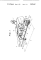
- FIG. 1 is a perspective view of one embodiment of the invention, partly broken off in order to show internal structures
- FIG. 2 is a vertical sectional view taken in a plane extending along the axis of the brush in FIG. 1 and looking at the structure from the back towards the front of FIG. 1;
- FIG. 3 is a partial side view of the apparatus, showing a left-hand portion of FIG. 2;
- FIG. 4 is a detail from FIG. 2, showing right-hand portions thereof in exploded condition.
- the invention comprises a brush unit which can be connected by a vacuum connector V to a suitable suction unit, not shown.
- Brush body 1 of a cylindrical brush 27 is horizontally disposed in a housing 25, parallel and adjacent to a vertical front wall 26 of this housing. Housing 25 also contains, behind the brush, a fractional horsepower motor 29 for driving the brush body 1 through a belt 28.
- bunches of bistles 7 suitably mounted on the outside of the brush body 1 dislodge the dust and dirt which is present on or in the floor covering to provide for removal of this dust and dirt through the vacuum connector V.
- the housing 25 has thin, vertical, parallel side walls 4 and 5, FIG. 2. It is shown as having in surface contact with inner surfaces of these side walls, equally thin mounting plates 23, 24.
- Brush body 1 is mounted in circular, coaxial apertures in the plates 23 and 24, by a brush adjustment device 2 and a brush release device 3.
- the latter devices 2, 3 are provided, respectively, at opposite ends of the brush body 1. They include, respectively, an eccentric 17 in the device 3 and an eccentric 18 in the device 2.
- a rigid rod 16 extends between the two eccentrics 17, 18. This rod is shown as also providing an axle for a pair of bearings 30 which provide for proper rotation of the brush body 1 about the rod 16.
- the rod extends through a central bore 16a in the brush body 1, which has two enlarged coaxial portions or recesses 12 and 13, one recess in each end portion of the brush body.
- These recesses 12, 13 contain the bearings 30. They also contain, closer to side walls 4 and 5, hub structures (31 at one end and 31a at the other end of the brush body 1) which are integral with eccentrics 17, 18, respectively.
- the eccentrics extend radially from respective ends of the hub structures 31, 31a for engagement with the apertures in the brush mounting plates 23, 24 of the side walls 4 and 5, respectively. Rotation of the eccentric 18 (at the left side of FIG. 2) is transmitted to the eccentric 17 (at the right side of FIG.
- This other eccentric and hub structure 17, 31 is best shown in FIG. 4. It includes the cylindrical hub 31, the center of which defines the axis 42 for rotation of the brush unit.
- the axis of the eccentric 17 is shown at 32; it is parallel to the axis 42 of rotation but is eccentrically displaced relative to the same.
- This displacement of the axis of rotation 42 serves to adjust the brush 27 relative to the housing 25 and is effected by turning the brush adjusting eccentric 18 from one position (shown at left in FIG. 2) into another position (shown at 2'--2' in FIG. 3).
- this eccentric and its hub 31a and the axle 16 are resiliently pressed a short distance into the housing 25, against a biasing force provided by a spring 22 in the hub 31 of the other eccentric 17.
- a dog 34 thereon previously detented in a slot 35 of the side wall plate 24 (FIG. 2) can be turned and newly detented in another similar slot (FIG. 3).
- the turning can be effected by inserting a tool, such as a screw driver or a coin, in a suitable slot 20 on the outside of the eccentric 18.
- this pressing-in and turning of the adjusting eccentric 18 can effect corresponding turning of the other eccentric 17, without removal of the latter from contact with its side wall plate 23, that is, by frictional sliding of a flange thereon along this side wall plate 23 (FIG. 2).
- the central rod 16 has an end portion 14 diametrically slotted at 41, for engaging a pair of ribs 39, 40 which project radially inwardly from the hub 31.
- a holding device is provided which is shown as including a spring clip 21 located on the outside of the hub 31 in a groove 21a surrounding this hub.
- a second peripheral groove 43 is formed on the end 14 of the rod 16 and is engaged by portions of the spring clip 21, which portions for this purpose extend inwardly to the inside of the hub 31, through at least one radial groove 43a in the inner end of the hub 31.
- the belt 28 is removed from the output shaft 36 of the motor 29; the eccentric 17 is disengaged from its side wall plate 23 (FIG. 2) by manually pressing it slightly into the housing against the pressure of the spring 22; and the eccentric 18 is removed from detent engagement with its side wall plate 24 by opposite pressure, manually against the force of the spring 22.
- the required sliding of the rod 16 relative to the housing 25 and eccentric 17 is provided by suitable dimensioning of the several parts, including the hub 31 and the ribs 39, 40 and grooves 21a, 43a therein, as will be understood readily from the drawing.
- the end portions 8 and 9 of the brush body 1 have bunches of brushes 7a secured thereto in oblique orientation so that these bristles extend laterally below and at least slightly beyond these side walls.
- the other bristles 7 of the brush 1 extend, as usual, through a bottom aperture 44 in the housing 25 (FIG. 3).
- the front end portion of the housing 25 may rest on rigid side wall portions 44a, the lower edges of which can be suitably adjusted, relative to the outer edges of the bristles 7 and 7a, by the aforementioned height adjusting and brush releasing structures 2, 3.
Landscapes
- Engineering & Computer Science (AREA)
- Mechanical Engineering (AREA)
- Nozzles For Electric Vacuum Cleaners (AREA)
- Brushes (AREA)
Applications Claiming Priority (2)
| Application Number | Priority Date | Filing Date | Title |
|---|---|---|---|
| DE2318425A DE2318425C2 (de) | 1973-04-12 | 1973-04-12 | Höhenverstell- und Wechseleinrichtung für eine antreibbare Walzenbürste eines Bodenpflegegerätes mit Staubabsaugung |
| DT2318425 | 1973-04-12 |
Publications (1)
| Publication Number | Publication Date |
|---|---|
| US3959847A true US3959847A (en) | 1976-06-01 |
Family
ID=5877837
Family Applications (1)
| Application Number | Title | Priority Date | Filing Date |
|---|---|---|---|
| US05/457,231 Expired - Lifetime US3959847A (en) | 1973-04-12 | 1974-04-02 | Floor cleaning apparatus |
Country Status (12)
| Country | Link |
|---|---|
| US (1) | US3959847A (cg-RX-API-DMAC7.html) |
| AT (1) | AT333693B (cg-RX-API-DMAC7.html) |
| BE (1) | BE811470A (cg-RX-API-DMAC7.html) |
| CA (1) | CA1007012A (cg-RX-API-DMAC7.html) |
| CH (1) | CH572730A5 (cg-RX-API-DMAC7.html) |
| DE (1) | DE2318425C2 (cg-RX-API-DMAC7.html) |
| ES (1) | ES425185A1 (cg-RX-API-DMAC7.html) |
| FR (1) | FR2225134B1 (cg-RX-API-DMAC7.html) |
| GB (1) | GB1461200A (cg-RX-API-DMAC7.html) |
| IT (1) | IT1004202B (cg-RX-API-DMAC7.html) |
| NL (1) | NL178389C (cg-RX-API-DMAC7.html) |
| SE (1) | SE406700B (cg-RX-API-DMAC7.html) |
Cited By (19)
| Publication number | Priority date | Publication date | Assignee | Title |
|---|---|---|---|---|
| US4221019A (en) * | 1978-04-20 | 1980-09-09 | Vorwerk & Co Interhaolding GmbH | Floorcare device |
| US4222146A (en) * | 1978-12-29 | 1980-09-16 | Samuel Hertzberg | Vacuum cleaners |
| US4361929A (en) * | 1981-03-26 | 1982-12-07 | Black & Decker Inc. | Vacuum cleaner tool having a two-position rotary brush |
| US4701975A (en) * | 1984-10-09 | 1987-10-27 | National Union Electric Corp. | Vacuum cleaner assembly |
| US5014387A (en) * | 1989-12-26 | 1991-05-14 | The Scott Fetzer Company | Brush roll mounting |
| US5193243A (en) * | 1989-12-26 | 1993-03-16 | The Scott Fetzer Company | Brushroll |
| US5272785A (en) * | 1989-12-26 | 1993-12-28 | The Scott Fetzer Company | Brushroll |
| US5598600A (en) * | 1989-12-26 | 1997-02-04 | The Scott Fetzer Company | Brushroll |
| US6314611B1 (en) | 2000-03-24 | 2001-11-13 | Baker Mcmillen Co. | Bladed disk brush roller assembly for a vacuum cleaner sweeper |
| US6574823B1 (en) | 2001-02-12 | 2003-06-10 | The Scott Fetzer Company | Brushroll |
| US6591441B2 (en) * | 2001-10-10 | 2003-07-15 | The Scott Fetzer Company | Brushroll having improved cleaning capability |
| US6760952B1 (en) | 2003-06-20 | 2004-07-13 | The Scott Fetzer Company | Vacuum cleaner brushroll |
| US6763549B1 (en) | 2001-09-07 | 2004-07-20 | Rudolph W. Peters | Edge cleaning vacuum cleaner apparatus |
| US20050091788A1 (en) * | 2003-10-30 | 2005-05-05 | Forsberg Bruce W. | Powered edge cleaning vacuum |
| US20050218713A1 (en) * | 2004-04-05 | 2005-10-06 | Oreck Holdings, Llc | Height adjustment apparatus for a rotatable component of a vacuum cleaner |
| WO2006061045A1 (de) * | 2004-12-11 | 2006-06-15 | Alfred Kärcher Gmbh & Co. Kg | Bodenreinigungsgerät |
| US20110047746A1 (en) * | 2009-09-01 | 2011-03-03 | Mark Butts | Vacuum cleaner accessory tool having a removable brush |
| US20120090133A1 (en) * | 2009-06-30 | 2012-04-19 | Sung-Guen Kim | Robot cleaner |
| US20160198920A1 (en) * | 2013-09-23 | 2016-07-14 | Alfred Kärcher Gmbh & Co. Kg | Suction nozzle apparatus for a cleaning device, and cleaning device |
Families Citing this family (5)
| Publication number | Priority date | Publication date | Assignee | Title |
|---|---|---|---|---|
| DE2826133C2 (de) * | 1978-06-15 | 1986-04-17 | Vorwerk & Co Interholding Gmbh, 5600 Wuppertal | Schaltungsanordnung zur Kenntlichmachung der für optimalen Betrieb richtigen, aus dem Gerätegehäuse herausragenden Borstenlänge von Borstenwalzen in Bodenpflegegeräten |
| EP0437109A3 (en) * | 1990-01-12 | 1991-10-30 | Trc Acquisition Corporation | Hand-held corded vacuum cleaner |
| IT1310795B1 (it) * | 1999-12-10 | 2002-02-22 | Vidoni Mario | Apparecchio di pulizia con spazzola intercambiabile |
| DE102004046383B4 (de) * | 2004-09-24 | 2009-06-18 | Stein & Co Gmbh | Vorrichtung für Bürstwalze von Bodenpflegegeräten |
| WO2021083950A1 (de) | 2019-10-28 | 2021-05-06 | Fraunhofer-Gesellschaft zur Förderung der angewandten Forschung eingetragener Verein | Antimikrobielle ausrüstung von oberflächen und vorrichtungen dafür |
Citations (5)
| Publication number | Priority date | Publication date | Assignee | Title |
|---|---|---|---|---|
| US1483972A (en) * | 1918-06-10 | 1924-02-19 | Hoover Co | Suction cleaner |
| US2072956A (en) * | 1933-10-06 | 1937-03-09 | P A Geier Co | Suction cleaner brush |
| US2130325A (en) * | 1935-02-18 | 1938-09-13 | Scott & Fetzer Co | Suction sweeper |
| US2668979A (en) * | 1949-10-29 | 1954-02-16 | Scott & Fetzer Co | Vacuum cleaner nozzle with detachable brush carrying unit |
| US3744077A (en) * | 1970-07-08 | 1973-07-10 | Brush S Co Ltd | Carpet sweepers |
Family Cites Families (2)
| Publication number | Priority date | Publication date | Assignee | Title |
|---|---|---|---|---|
| FR382885A (fr) * | 1906-10-15 | 1908-02-18 | Levi H Springer | Porte d'extrémité de wagon |
| US2054194A (en) * | 1934-10-01 | 1936-09-15 | Abraham Cooper | Removable roller mounting |
-
1973
- 1973-04-12 DE DE2318425A patent/DE2318425C2/de not_active Expired
-
1974
- 1974-02-22 BE BE141300A patent/BE811470A/xx unknown
- 1974-02-22 CH CH266074A patent/CH572730A5/xx not_active IP Right Cessation
- 1974-03-06 FR FR7407553A patent/FR2225134B1/fr not_active Expired
- 1974-03-14 NL NLAANVRAGE7403416,A patent/NL178389C/xx not_active IP Right Cessation
- 1974-03-15 GB GB1174174A patent/GB1461200A/en not_active Expired
- 1974-04-02 US US05/457,231 patent/US3959847A/en not_active Expired - Lifetime
- 1974-04-09 CA CA197,214A patent/CA1007012A/en not_active Expired
- 1974-04-09 ES ES425185A patent/ES425185A1/es not_active Expired
- 1974-04-10 IT IT50298/74A patent/IT1004202B/it active
- 1974-04-10 SE SE7404883A patent/SE406700B/xx not_active IP Right Cessation
- 1974-04-11 AT AT304874A patent/AT333693B/de not_active IP Right Cessation
Patent Citations (5)
| Publication number | Priority date | Publication date | Assignee | Title |
|---|---|---|---|---|
| US1483972A (en) * | 1918-06-10 | 1924-02-19 | Hoover Co | Suction cleaner |
| US2072956A (en) * | 1933-10-06 | 1937-03-09 | P A Geier Co | Suction cleaner brush |
| US2130325A (en) * | 1935-02-18 | 1938-09-13 | Scott & Fetzer Co | Suction sweeper |
| US2668979A (en) * | 1949-10-29 | 1954-02-16 | Scott & Fetzer Co | Vacuum cleaner nozzle with detachable brush carrying unit |
| US3744077A (en) * | 1970-07-08 | 1973-07-10 | Brush S Co Ltd | Carpet sweepers |
Cited By (24)
| Publication number | Priority date | Publication date | Assignee | Title |
|---|---|---|---|---|
| US4221019A (en) * | 1978-04-20 | 1980-09-09 | Vorwerk & Co Interhaolding GmbH | Floorcare device |
| US4222146A (en) * | 1978-12-29 | 1980-09-16 | Samuel Hertzberg | Vacuum cleaners |
| US4361929A (en) * | 1981-03-26 | 1982-12-07 | Black & Decker Inc. | Vacuum cleaner tool having a two-position rotary brush |
| US4701975A (en) * | 1984-10-09 | 1987-10-27 | National Union Electric Corp. | Vacuum cleaner assembly |
| US5272785A (en) * | 1989-12-26 | 1993-12-28 | The Scott Fetzer Company | Brushroll |
| US5193243A (en) * | 1989-12-26 | 1993-03-16 | The Scott Fetzer Company | Brushroll |
| US5373603A (en) * | 1989-12-26 | 1994-12-20 | The Scott Fetzer Company | Brushroll |
| US5598600A (en) * | 1989-12-26 | 1997-02-04 | The Scott Fetzer Company | Brushroll |
| US5014387A (en) * | 1989-12-26 | 1991-05-14 | The Scott Fetzer Company | Brush roll mounting |
| US6314611B1 (en) | 2000-03-24 | 2001-11-13 | Baker Mcmillen Co. | Bladed disk brush roller assembly for a vacuum cleaner sweeper |
| US6574823B1 (en) | 2001-02-12 | 2003-06-10 | The Scott Fetzer Company | Brushroll |
| US6763549B1 (en) | 2001-09-07 | 2004-07-20 | Rudolph W. Peters | Edge cleaning vacuum cleaner apparatus |
| US6591441B2 (en) * | 2001-10-10 | 2003-07-15 | The Scott Fetzer Company | Brushroll having improved cleaning capability |
| US6760952B1 (en) | 2003-06-20 | 2004-07-13 | The Scott Fetzer Company | Vacuum cleaner brushroll |
| US20050091788A1 (en) * | 2003-10-30 | 2005-05-05 | Forsberg Bruce W. | Powered edge cleaning vacuum |
| US20050218713A1 (en) * | 2004-04-05 | 2005-10-06 | Oreck Holdings, Llc | Height adjustment apparatus for a rotatable component of a vacuum cleaner |
| WO2006001865A1 (en) * | 2004-04-05 | 2006-01-05 | Oreck Holdings, Llc | Height adjustment apparatus for a rotatable component of a vacuum cleaner |
| US7305736B2 (en) | 2004-04-05 | 2007-12-11 | Oreck Holdings, Llc | Height adjustment apparatus for a rotatable component of a vacuum cleaner |
| WO2006061045A1 (de) * | 2004-12-11 | 2006-06-15 | Alfred Kärcher Gmbh & Co. Kg | Bodenreinigungsgerät |
| US20120090133A1 (en) * | 2009-06-30 | 2012-04-19 | Sung-Guen Kim | Robot cleaner |
| US8832902B2 (en) * | 2009-06-30 | 2014-09-16 | Lg Electronics Inc. | Robot cleaner |
| US20110047746A1 (en) * | 2009-09-01 | 2011-03-03 | Mark Butts | Vacuum cleaner accessory tool having a removable brush |
| US8037571B2 (en) * | 2009-09-01 | 2011-10-18 | Techtronic Floor Care Technology Limited | Vacuum cleaner accessory tool having a removable brush |
| US20160198920A1 (en) * | 2013-09-23 | 2016-07-14 | Alfred Kärcher Gmbh & Co. Kg | Suction nozzle apparatus for a cleaning device, and cleaning device |
Also Published As
| Publication number | Publication date |
|---|---|
| NL178389B (nl) | 1985-10-16 |
| NL7403416A (cg-RX-API-DMAC7.html) | 1974-10-15 |
| FR2225134A1 (cg-RX-API-DMAC7.html) | 1974-11-08 |
| DE2318425C2 (de) | 1982-05-13 |
| NL178389C (nl) | 1986-03-17 |
| AT333693B (de) | 1976-12-10 |
| CH572730A5 (cg-RX-API-DMAC7.html) | 1976-02-27 |
| CA1007012A (en) | 1977-03-22 |
| ES425185A1 (es) | 1976-07-01 |
| BE811470A (fr) | 1974-06-17 |
| FR2225134B1 (cg-RX-API-DMAC7.html) | 1977-09-23 |
| SE406700B (sv) | 1979-02-26 |
| DE2318425A1 (de) | 1974-10-31 |
| IT1004202B (it) | 1976-07-10 |
| ATA304874A (de) | 1976-04-15 |
| GB1461200A (en) | 1977-01-13 |
Similar Documents
| Publication | Publication Date | Title |
|---|---|---|
| US3959847A (en) | Floor cleaning apparatus | |
| CN211559926U (zh) | 地刷组件及清洁装置 | |
| US5031315A (en) | Shaving apparatus | |
| US2999258A (en) | Surface-cleaning and rug-shampooing machines | |
| GB2257620A (en) | Carpet sweeper | |
| KR20050084895A (ko) | 랜덤 오비탈 칫솔 | |
| SE438777B (sv) | Dammsugningsmunstycke | |
| JPS6219330Y2 (cg-RX-API-DMAC7.html) | ||
| KR910002390B1 (ko) | 수동소제기 | |
| US5134744A (en) | Beater brush roller of vacuum cleaner beater brush assembly | |
| US1773961A (en) | Vacuum sweeper | |
| US5819352A (en) | Mount for motorized broom | |
| US1972745A (en) | Suction cleaning apparatus | |
| CN114668348B (zh) | 一种毛刷滚筒及配置该毛刷滚筒的洗地机 | |
| CN217162017U (zh) | 清洁机构及清洁设备 | |
| JP2002028113A (ja) | 電気掃除機 | |
| KR101073102B1 (ko) | 로봇청소기 | |
| US5361442A (en) | Pool tile scrubber | |
| CN112617679B (zh) | 滚刷结构及扫地机器人 | |
| US2227971A (en) | Vacuum cleaner | |
| CN114947660B (zh) | 滚刷和自移机器人 | |
| CN114601403A (zh) | 一种可拆转动固定机构、清洁组件和清洁设备 | |
| JPH0667367B2 (ja) | 電気掃除機における回転ブラシの軸保持具 | |
| GB2288323A (en) | A vibrating brush | |
| JP7391822B2 (ja) | 電気掃除機の吸口体およびこれを備えた電気掃除機 |