US388902A - Saw-mill - Google Patents
Saw-mill Download PDFInfo
- Publication number
- US388902A US388902A US388902DA US388902A US 388902 A US388902 A US 388902A US 388902D A US388902D A US 388902DA US 388902 A US388902 A US 388902A
- Authority
- US
- United States
- Prior art keywords
- head
- rack
- block
- detent
- lever
- Prior art date
- Legal status (The legal status is an assumption and is not a legal conclusion. Google has not performed a legal analysis and makes no representation as to the accuracy of the status listed.)
- Expired - Lifetime
Links
- 210000003127 knee Anatomy 0.000 description 7
- 230000002441 reversible effect Effects 0.000 description 3
- 150000001875 compounds Chemical group 0.000 description 2
- 240000001973 Ficus microcarpa Species 0.000 description 1
- 240000007839 Kleinhovia hospita Species 0.000 description 1
- 230000003247 decreasing effect Effects 0.000 description 1
- 230000000284 resting effect Effects 0.000 description 1
- 230000000630 rising effect Effects 0.000 description 1
Images

Classifications
-
- B—PERFORMING OPERATIONS; TRANSPORTING
- B27—WORKING OR PRESERVING WOOD OR SIMILAR MATERIAL; NAILING OR STAPLING MACHINES IN GENERAL
- B27B—SAWS FOR WOOD OR SIMILAR MATERIAL; COMPONENTS OR ACCESSORIES THEREFOR
- B27B29/00—Gripping, clamping or holding devices for the trunk or log in saw mills or sawing machines; Travelling trunk or log carriages
- B27B29/08—Trunk or log carriages with gripping means designed to pass the saw blade(s), especially for band saws; Arrangement of gripping accessories thereon; Turning devices thereon
-
- Y—GENERAL TAGGING OF NEW TECHNOLOGICAL DEVELOPMENTS; GENERAL TAGGING OF CROSS-SECTIONAL TECHNOLOGIES SPANNING OVER SEVERAL SECTIONS OF THE IPC; TECHNICAL SUBJECTS COVERED BY FORMER USPC CROSS-REFERENCE ART COLLECTIONS [XRACs] AND DIGESTS
- Y10—TECHNICAL SUBJECTS COVERED BY FORMER USPC
- Y10T—TECHNICAL SUBJECTS COVERED BY FORMER US CLASSIFICATION
- Y10T83/00—Cutting
- Y10T83/647—With means to convey work relative to tool station
- Y10T83/6492—Plural passes of diminishing work piece through tool station
- Y10T83/6499—Work rectilinearly reciprocated through tool station
- Y10T83/6508—With means to cause movement of work transversely toward plane of cut
- Y10T83/6515—By means to define increment of movement toward plane of cut
- Y10T83/6518—By pusher mechanism
- Y10T83/652—With additional work holding or positioning means
- Y10T83/6521—Work holding means includes actuator
Definitions
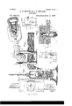
- Figure l of the drawings is a side elevation of the improved sawvmill attachment.
- Fig. 2 is a detail plan View of the rack-bar I, showing the pawls g q'.
- Fig. 3 is a detail plan view ofthe rack L, showing the pawls iu con nection therewith.
- Fig. .JL is adetail side elevation, partly in section, of the sliding head D and lever y.
- Fig. is avcrtical transverse section on the line .r a' of Fig. l.
- Fig. 6 is a longitudinal section on the line a: of Fig. 4; and
- Fig. 7 is a detail view of the vertical part c, broken away to show the brieflyt-block E.
- Fig. 8 is a detail back view of the sliding head, showing the clip d and block E.
- Fig. 9 is a detail end view of same.
- the invention relates to improvements in saw-mill carriages, and it consists in the coustruction and novel combination of parts, as hereinafter set forth.
- A designates the bed or way upon which the head-block B rests and moves.
- the carriage is composed of a front and rear portion, I) and b', respectively, the former, b, constituting the horizontal part, to which the vertical part c and the knee C are attached.
- I The vertical part 0 is provided with the way c', within which the hollow sliding head D is raised and lowered.
- the said way c is formed with grooves c2 at the sides of the recess ci, in which grooves the lateral danges cl of the clip d slide.
- G is au eccentric ou the end of the lever g. pivoted within the sliding head. By turning the lever downwardly on its pivotal point the eccentric bearing in the concavity will force the block g down upon the shank of the dog, so as to hold it in position.
- the outer end of the lever g is bifurcated, as shown, and between the arms of the bifurcated portion is secured the iuternallytappcd sleeve H, which engages the screw IL, provided atits outer end with a suitable handle and having on its Opposite end a stem, h, which is threaded to engage a nut, h2.
- I is a slide-bar resting against the side of the eccentric-leverg and having at one end the transverse ring or collar i, engaging the stem h between the nut h2 and the end of the screw h.
- the opposite end of the slide-har has a head similar in shape to the eccentric G, provided with a rectangular opening, i', and having its outer face, 13"', outwardly inclined toward its rounded end, forming a transverse shoulder, ii, plainly seen in Fig. 6.
- the pivotpin J has its portionj within the sliding head squared to engage the square eye through the eccentric and turn therewith.
- the part b ofthe head-bloek has on its under surface the cogs b3, .to prevent its sliding on the way.
- L L are pivotal brackets secured opposite each other at each side of the rack L at a suitable point on the part b of the head-block.
- the pin Z having bearingsin the brackets L,has pivoted upon it between said brackets the forwardlystanding pawls Z Z', preferably four in nurnber, decreasing in length about one-twelfth of an inch from the longest to the shortest, and engaging the rack L, so as to prevent the retraction ot' the knee C when moved outward from the part b of the headblock.
- a disengaging-rod, Z2 is journaled iu bearings on the front feet of the brackets L', and has its central portion under the pawls Z bent rectangularly outward and upward, so that by moving the arm Z3 of said rod the pawls can be engaged or disengaged.
Landscapes
- Life Sciences & Earth Sciences (AREA)
- Engineering & Computer Science (AREA)
- Mechanical Engineering (AREA)
- Wood Science & Technology (AREA)
- Forests & Forestry (AREA)
- Orthopedics, Nursing, And Contraception (AREA)
- Prostheses (AREA)
Description
2 Sheeiss--Sllee 1. S. P. MOORB: J. C. MILLER.
(No Model.)
SAW MILL.
N0. 388,902.' Patented Sept. 4', `1888.
To 0 V. mf, S
WITNESSES Je@ @M .WFM a@ Attorney,
N. PETERS. Pme-Lnhngnpmr, wxsmngxm n. t;
(No Model.) 2 Sheets-Sheet 2.
S. 2E. MOORE 8v J. C.. MILLER.
SAW MILL.
No. 888,902. Patented Sept. 4, 1888.
d w Homey UNITED STATES PATENT rricE.
SIDNEY F. MOORE, OF FOR-EST, AND JOHN O. MILLER, OF DUNKIRK, OHIO.
SAW-
SPECIFICATION forming part of Letters Patent No. 388,902, dated September 4, 1888.
Application liled June 25, i587 To all whom, it may concern,.-
Beit known that we, SIDNEY F. MOORE, of Forest, county of Hardiu,and JOHN C. MILLER, a rcsideutofDuukirk, in the county of Hardin, and State of Ohio, both citizens of the United States, have invented certain new and useful Improvements in Saw-Mills; and we do declare the following to be a full, clear, and exact description oi' the invention, such as will enable others skilled in the art to which it appertains to make and use the same, reference being had to the accompanying drawings, and to letters or figures of reference marked thereon, which form a part of this specification.
Figure l of the drawings is a side elevation of the improved sawvmill attachment. Fig. 2 is a detail plan View of the rack-bar I, showing the pawls g q'. Fig. 3 isa detail plan view ofthe rack L, showing the pawls iu con nection therewith. Fig. .JL is adetail side elevation, partly in section, of the sliding head D and lever y. Fig. is avcrtical transverse section on the line .r a' of Fig. l. Fig. 6 is a longitudinal section on the line a: of Fig. 4; and Fig. 7 is a detail view of the vertical part c, broken away to show the datent-block E. Fig. 8 is a detail back view of the sliding head, showing the clip d and block E. Fig. 9 is a detail end view of same.
The invention relates to improvements in saw-mill carriages, and it consists in the coustruction and novel combination of parts, as hereinafter set forth.
Referring by letters of reference to the drawings, A designates the bed or way upon which the head-block B rests and moves. The carriage is composed of a front and rear portion, I) and b', respectively, the former, b, constituting the horizontal part, to which the vertical part c and the knee C are attached. IThe vertical part 0 is provided with the way c', within which the hollow sliding head D is raised and lowered. The said way c is formed with grooves c2 at the sides of the recess ci, in which grooves the lateral danges cl of the clip d slide. The clip d is secured to the inner face of the sliding head D, and is cut away transversely to the inner face of the sliding head to form a seat for the detent-block E, as shown in Fig. 7. The detent-hlock E is provided with lateral flanges similar to the anges d ou the clip. Its portion from the ange to the side adjacent to the sliding head, however, is somewhat less in thickness than the cor Serial No.2-12,508. (No model.)
responding portion of thc clip, so that when the detent-block is drawn toward the sliding block its respective flanges bind ou the adjacent inward projections of the grooves cAz and hold the head in any desired position.
F isa dog having the shank fprovidcd with parallel edges and the pointfto enter the log to be sawed. The dog is seated in slot-openiugsfifs through the front and rear walls of the hollow sliding head. The dog tits rather loosely in the openings when not locked, so that it can be tilted as the point is driven into the log. A rectangular block, g', rests upon the upper edge of the shank of the dog within the hollow head D, and its upper edge is preferably made concave longitudinally.
G is au eccentric ou the end of the lever g. pivoted within the sliding head. By turning the lever downwardly on its pivotal point the eccentric bearing in the concavity will force the block g down upon the shank of the dog, so as to hold it in position. The outer end of the lever g is bifurcated, as shown, and between the arms of the bifurcated portion is secured the iuternallytappcd sleeve H, which engages the screw IL, provided atits outer end with a suitable handle and having on its Opposite end a stem, h, which is threaded to engage a nut, h2.
I is a slide-bar resting against the side of the eccentric-leverg and having at one end the transverse ring or collar i, engaging the stem h between the nut h2 and the end of the screw h. The opposite end of the slide-har has a head similar in shape to the eccentric G, provided with a rectangular opening, i', and having its outer face, 13"', outwardly inclined toward its rounded end, forming a transverse shoulder, ii, plainly seen in Fig. 6. The pivotpin J has its portionj within the sliding head squared to engage the square eye through the eccentric and turn therewith. The outer end of said pin .I is reduced and provided with a thread to engage a tapped nut, and its inner end has a bearing through the inner wall of the sliding head, and its reduced cyiiudrical stcmj passes through an opening in the detent-block E to the rear face thereof, where it is threaded and provided with a nut countersunk into the face of the block.
K is a sleeve provided with a squared axial opening adapted to slide upon the partj of the pivot-piu, which extends outwardly bel youu the inenten ne@ of uw head of the slide-bar. The inner end of the sleeve K is inclined, as at 7c, reversely to the incline Z2, upon which it impinges, and the said sleeve is held in place by the nut y on the outer end of the p in. The squared portion of the pin also passes loosely through the rectangular opening Z. When the slide-bar I is drawn longitudinally outward by means of the screw h within the sleeve H, the inclined face izforces the sleeve K outwardly, thus causing the detent-bloek E to bind upon theinwardly-projeeting portions of the grooves e2. The lower part ot' the knee C extends longitudinally, and has secured to it the straight rack-bar L, which has the vertical sides of its teeth toward the end of the bar opposite the knee. The rack-bar moves on the way b,made on the rear part, b', ofthe head-block, and serves a purpose hereinafter explained. The part b ofthe head-bloek has on its under surface the cogs b3, .to prevent its sliding on the way. L L are pivotal brackets secured opposite each other at each side of the rack L at a suitable point on the part b of the head-block. The pin Z, having bearingsin the brackets L,has pivoted upon it between said brackets the forwardlystanding pawls Z Z', preferably four in nurnber, decreasing in length about one-twelfth of an inch from the longest to the shortest, and engaging the rack L, so as to prevent the retraction ot' the knee C when moved outward from the part b of the headblock.
A disengaging-rod, Z2, is journaled iu bearings on the front feet of the brackets L', and has its central portion under the pawls Z bent rectangularly outward and upward, so that by moving the arm Z3 of said rod the pawls can be engaged or disengaged.
M is a lever bifurcated at its lower end and having the arms m of said bifurcation pivoted on the pin Z outside the brackets L.
N is a rectangular boxtrunnioned in bearings in the arms m atasuitable distance above the pivotal pin Z. The said box has passing through it the rack-bar O, pivotally connected at its front bifureated end to the rear lower portion of the extension-knee and provided with three separate racks, the central one, o, of which is provided with teeth having their shoulders frontward, while the teeth of theside racks, o', are shouldered oppositely thereto. The trunnions P, journaled in the arms m, allow the box Ny to retain a position parallel .with the rack-bar O when the lever M is op erated.
Q represents a compound or reversible detent pivoted on the journal z within the box N, the central pawl, q, of which is designed to engage the central rack, o, when the lever is operated to retract the knee, and the oppositely-eurved pawls q are designed to reverse the motion when put in engagement with the racks o by turning the detent on its pivot to face in a reverse direction, and a pin, g2, standing laterally from the detent is provided, so that the detent can be reversed by the operator with his foot.
R is a curved rack concentric with the pin Z and supported on standards rising from the part I1 of the head-block; and r is a pawl pivoted to the lever M, adapted to hold the lever in its adjusted position.
Having thus described our invention, We claim- 1. The combination, with the saw-mill carriage-knee provided with the vertical way c', having the grooved edges, of the hollow head provided with the flanged clip ou its side to move in said grooved way, the eccentric pivoted in said head, the detent-block E, and the pin for clamping said detent-block, substantially as specified.
2. The combination, with the extensionknee, the headblock consisting of the two parts b b', the rack, the rack-bar L, secured to the knee and moving on ways on the carriage, and the rack-bar O, pivoted on the knee, of the lever M, the pawls engaging the rack L. the rod for engaging and disengaging said pawls, the box N, having the trunnion-bearings I?, and the compound/detent Q, having the pivotal bearing .e in said box, substantially as specilied.
3. The combination, with the extensionknee having the vertical grooved way and the hollow sliding 'head D, of the lever g, having the eccentric-head pivoted within the head, theV detent-block g', the internally-threadedsleeve H, secured within the bifurcated outer end ofthe lever g, the screw engaging in the threaded sleeve, the slotted slide-bar I, provided with the inclined face Z2, the sleeve having the inclined end 7c, corresponding to the incline 2,and provided with the axial opening to iit upon the squared part of the pivotal -pin having the squared portion and thelnut,
substantially as specified.
4. The combination, with 4the extensionknee, the head D, having a flanged clip, d', moving in the vertical way having the lateral grooves, and the dog carried by said head, of,
detent pivoted within said box, the rack R, y
curved concentrcally with the pivotal point Z, and the pawl secured to said lever and engaging the rack, substantially as specified.
In testimony whereof we affix our signatures in presence of two witnesses.
SIDNEY F. MOORE. JOHN C. MILLER.
Witnesses:
JOHN CAMPBELL, H. C. VIKOFF.
IOO
IIO
Publications (1)
| Publication Number | Publication Date |
|---|---|
| US388902A true US388902A (en) | 1888-09-04 |
Family
ID=2457882
Family Applications (1)
| Application Number | Title | Priority Date | Filing Date |
|---|---|---|---|
| US388902D Expired - Lifetime US388902A (en) | Saw-mill |
Country Status (1)
| Country | Link |
|---|---|
| US (1) | US388902A (en) |
-
0
- US US388902D patent/US388902A/en not_active Expired - Lifetime
Similar Documents
| Publication | Publication Date | Title |
|---|---|---|
| US388902A (en) | Saw-mill | |
| US147916A (en) | Improvement in lifting-jacks | |
| US287124A (en) | John h | |
| US328550A (en) | Combined anvil | |
| US272734A (en) | Gage for rip-saws | |
| US130449A (en) | Improvement in lifting-jacks | |
| US378082A (en) | clabk | |
| US81381A (en) | Improvement in joinebs clamps | |
| US525706A (en) | Lifting or log jack | |
| US883032A (en) | Log-dumping device. | |
| US508975A (en) | Reversible saw-handle | |
| US289815A (en) | Attachment for logging-sleds | |
| US130542A (en) | Improvement in lifting-jacks | |
| US265999A (en) | Railroad-track gage and level | |
| US58586A (en) | Improvement in sawing-mach ines | |
| US236620A (en) | Shingle-sawing machine | |
| US106655A (en) | Improvement in saw-mill dogs | |
| US134086A (en) | Improvement in lifting-jacks | |
| US332051A (en) | Wrench | |
| US577889A (en) | Gage-roll for sawmills | |
| US39566A (en) | Improvement in stocks for | |
| US386566A (en) | Bo ring-mac mine | |
| US151613A (en) | Improvement in dogs for saw-mill head-blocks | |
| US989355A (en) | Bench-shears. | |
| US156916A (en) | Improvement in holding-jacks for wagon-bodies |