US3884462A - Mobile geometrical form - Google Patents
Mobile geometrical form Download PDFInfo
- Publication number
- US3884462A US3884462A US428201A US42820173A US3884462A US 3884462 A US3884462 A US 3884462A US 428201 A US428201 A US 428201A US 42820173 A US42820173 A US 42820173A US 3884462 A US3884462 A US 3884462A
- Authority
- US
- United States
- Prior art keywords
- strip
- geometrical form
- mobile
- opposing
- edge
- Prior art date
- Legal status (The legal status is an assumption and is not a legal conclusion. Google has not performed a legal analysis and makes no representation as to the accuracy of the status listed.)
- Expired - Lifetime
Links
Images



Classifications
-
- B—PERFORMING OPERATIONS; TRANSPORTING
- B44—DECORATIVE ARTS
- B44C—PRODUCING DECORATIVE EFFECTS; MOSAICS; TARSIA WORK; PAPERHANGING
- B44C3/00—Processes, not specifically provided for elsewhere, for producing ornamental structures
Definitions
- ABSTRACT A mobile geometrical form in the general shape of a hyperbolic paraboloid is described as made from a continuous strip of material to form a continuously twisted shape having both an external edge and an in ternal edge.
- the internal edge of the form defines an opening centrally in the form.
- the form has two distinct continuous surfaces on opposing sides of the strip from which the form is made. Each side or surface has four lines of inflection to result in four surface portions having successive concave and convex contours. Opposing surface portions of the strip between the same inflection lines have opposing concave and convex contours.
- the form is made of a semi-rigid flexible material such as sheet metal.
- the strip can assume the predetermined geometrical form in an infinite number of relative positions of the strip.
- the stresses established in the strip redistribute themselves in each relative position of the strip as the latter translates along a path generally defined by the form itself to maintain the shape of the same.
- the mobile geometrical form of the present invention which is in the general shape of a hyperbolic paraboloid, is made of a semi-rigid flexible material.
- the strip assumes the novel geometrical form in an infinite number of relative positions of the strip.
- Translatory motion of the strip within a general path outlined by the form, redistributes the stresses established in the strip in each position of the latter to maintain the shape of the geometrical form.
- the forces required to translate the strip within its general outline or shape are a function of the flexibility of the material from which it is made and can be reduced to minimal values.
- the novel and aesthetically pleasing form of the present invention can be utilized both for ornamental purposes as well as other mechanical utilitarian purposes.
- the form is particularly suitable as a reciprocating movement or motion device.
- the novel form can be utilized to convert linear into curvilinear movements or vice versa.
- Other important uses of the device include amusement and exercise.
- the form can be continuously or reciprocally advanced while continuously maintaining a fixed grip on two points of the form. This suggests possible use in physical therapy applications to provide exercise to muscles in the arms and wrists.
- a mobile geometrical form in accordance with the present invention comprises a double-sided continuous strip of material, each side having four points of inflection to thereby result in four surface portions having excessive concave and convex contours. Opposing surface portions of said strip between the same inflection points have opposing concave and convex contours.
- the double-sided continuous strip of material is twisted to cause each surface to include two portions thereof which substantially face each other and two portions which are substantially directed away from one another, the portions facing each other and the portions directed in opposing directions being symmetrically disposed about and substantially parallel to respective planes which are normal to one another.
- the novel mobile geometrical form of the present invention is in the form of a hyperbolic paraboloid which, when formed from a continuous strip of material, exhibits both an external edge and in internal edge, with the internal edge forming an opening centrally of the form.
- the strip of material is made from a semi-rigid flexible material.
- the strip assumes the geometrical form in an infinite number of relative positions of the strip. The stresses established in the strip redistribute themselves in each relative po sition of the strip to maintain the shape of the geometrical form.
- the external and internal edges of the form are smooth.
- protuberances in the form of projections may be provided on the internal, external or both edges.
- the mobile geometrical form adds extra dimensions for possible uses to which it can be applied.
- such a geometrical form can be utilized for ornamental, amusement, exercising, and mechanical uses.
- FIGS. 1 and 2 are top plan views of slitted annular strips from which the mobile geometrical form in accordance with the present invention may be formed;
- FIG. 3 is a side elevational view of the two annular strips shown in FIG. 1 when the strips are concentrically disposed and opposing edges are joined to permit the connected annular strips or resultant strip to be stretched along the general direction of the axis into the general shape of a helicoid;
- FIG. 4 is a perspective view of the helicoid shown in FIG. 3, showing the manner in which the helicoid is formed by separation of the free ends of the respective annular strips;
- FIG. 5 is a front elevational view of the connected strips after one of the free ends of the resultant strip is bent to bring portions of one of the resulting surfaces of the helicoid onto itself whereby portions of a single surface face each other;
- FIG. 6 is similar to FIG. 5, showing the condition when one of the free ends has been brought adjacently to the other free end and wherein the free ends are aligned to bring the corresponding surfaces at the free ends to positions generally facing the same direction;
- FIG. 7 is similar to FIG. 6, showing the condition when the free ends are joined to each other to thereby cause each of the original helicoid surfaces to form a continuous surface once all the opposing edges have been connected;
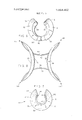
- FIG. 8 is a front elevational view of the novel geometrical form resulting from the above suggested and illustrated construction, the form being generally in the shape of a hyperbolic paraboloid which defines an external edge and an internal edge, with the internal edge forming an opening centrally of the form;
- FIGS. 9 and 10 are perspective views of the geometrical form shown in FIG. 8, taken from different angles to clearly illutrate the novel form;
- FIGS. 11-16 are front elevational views similar to FIG. 8, each view showing two points at slightly translated positions, the FIGURES showing the manner in which the form of the present invention permits, when made of a semi-rigid flexible material, translation or movement of the strip along a path generally defined by the extent of the latter.
- the strip may thus assume an infinite number of relative positions with the stresses established in the strip redistributing themselves in each relative position to maintain the shape of the geometrical form.
- FIGS. ll-16 illustrate translatory movement of the strip to thereby result in all points on the strip moving, it is also possible to fix one point on the strip.
- move- ,ment of the type suggested in FIGS. 11-16 causes the geometrical form to reciprocate from side to side about the fixed point while including curvilinear nutatingtype movement;
- FIGS. 17 and 18 are similar to FIGS. 1 and 2, but showing a plurality of projections along the length of the internal edge extending in the direction generally centrally of the annular discs;
- FIG. 19 is a perspective view of a second embodiment of a mobile geometrical form in accordance with the present invention made from the discs shown in FIGS. 17 and 18.
- the mobile geometrical form in accordance with the present invention will be described as being formed of two slitted annular strips 10 and 30. While the description will be outlined in the order in which the strips are assembled to ultimately form the novel form or shape, it is pointed out that the same or similar form need not be formed from two individual strips but may be molded or constructed from a single continuous strip.
- the annular strip 10 includes a disc 12 having an upper surface 14 and a lower surface 16, as viewed in FIG. 1.
- the disc 12 is provided with a slit 18 to form an end portion 20, marked with an A, and an opposing end portion 22, marked with a B.
- the annular strip 30 includes a disc 32 having an upper surface 34 ,and a lower surface 36, as viewed in FIG. 2.
- the disc 32 is provided with a slit 38 to thereby form opposing end portions 40 and 42, respectively designated by the letters B and A.
- the annular strip 10 is provided with a central opening 24.
- the central opening 24 is defined by a smooth internal edge 26.
- the external periphery or edge contour is defined by a smooth edge 28.
- the internal and external edges 26 are shown as simple concentric circular edges. Modifications of the internal and external edges will be more fully described in connection with FIGS. 17-19.
- annular strip 30 is provided with a central opening 44 defined by a circular smooth internal edge 46.
- the external circular edge 48 is concentric with the internal edge 46 and is similarly smooth.
- the first step in assembling the annular strips 10 and 30 is to dispose the strips one on top of the other in a concentric fashion whereby the discs 12 and 32 overlap with the slits 18 and 38 aligned.
- the end portion 20 is disposed contiguous to the end portion 40 while the end portion 22 is contiguous to the end portion 42.
- An end portion to the right of the slit of one of the strips is now joined to an end portion to the left of a respective slit on the other strip.
- either the end portion 20 may be joined to the end portion 42 or the end portion 22 may be joined to the end portion 40.
- the particular set of end portions which are connected in this manner is not critical and the same ultimate results are obtained, as will become evident hereafter.
- the end portions 20 and 42 have been joined in the example presently being described.
- the joint 50 may be formed by connecting the end portions 20 and 42 in any conventional means, such as with screws and wing nuts 52.
- the resulting form is generally described as a right helicoid when the remaining free end portions 22 and 40 are separated from each other or the resulting strip is stretched generally along the axis of symmetry.
- FIG. 4 the resulting helicoid is shown when the end portions 22 and 40 are moved in opposing directions.
- the effect of joining the two annular strips 10 and 30 in this fashion causes the upper surfaces 14 and 34 to merge and define a continuous helical surface.
- the lower surfaces 16 and 36 of the respective annular strips 10 and 30 similarly merge to form a helical surface.
- the upper surfaces 14 and 34 generally face asingle direction along the axis of the resulting helicoid while the lower surfaces 16 and 36 similarly face a single opposing direction along the axis.
- FIG. 4 Also shown in FIG. 4 are cutout portions 54 at the end portion 22 while bolts 56 are shown projecting from the end portion 40 which are adapted to be received within the cutout portions 54 when the free ends of the helicoid are joined in a manner to be described hereafter.
- the annular strips and 30 are made of a semi-rigid flexible material. This material may either be sheet metal or a sheet of elastomeric plastic material. The thickness and hardness of the annular strips will determine the ease with which the resulting geometrical form can be shifted or translated along itself, as will become evident hereafter.
- the next step in the assembly of the construction of the form is the bending of one free end of the resulting spiral or helicoid shown in FIG. 3 to cause, in the example shown in FIG. 5, lower surface portions 16' and 36 to face each other.
- the configuration shown in FIG. 5 is achieved by bending the disc 32 at the end portion 40 inwardly or towards the end portions 20 and 42 and bringing the lower surface 36 in the region of the end portion 40 to a facing condition with respect to the lower surface 16 of the disc 12.
- the end portion 40 is continuously moved along the lower surface 16 in a generally counter-clockwise direction, as viewed in FIG. 4, until the end portion 40 is disposed adjacent to the end portion 22.
- the final step of the construction process is the joining of the free ends to each other at a second joint 58, shown in FIG. 7.
- the resulting mobile shape or form is generally designated by the reference numeral 60. It will be noted that the form 60 merges the original upper surfaces 14 and 34 into a continuous surface. Similarly, the original lower surfaces 16 and 36 of the component annular strips are similarly merged into a continuous surface.
- novel mobile form 60 now includes an internal edge 62 which represents the original internal edges 26 and 46 which merge when the annular strips are joined as described. Similarly, a new continuous external edge 64 is defined by the form 60 which replaces the original external edges 28 and 48 of the two component strips.
- the above described continuous edges and surfaces are shown in FIGS. 7 and 9.
- the novel mobile shape or form 60 defines an interesting mathematical warped surface resembling, in certain respects, the doubly ruled hyperbolic paraboloid.
- the hyperbolic paraboloid is formed of a solid warped or deformed planar sheet.
- the form 60 of the present invention is in the form of a continuous warped strip having a finite width.
- an internal edge 62 is defined which forms a central opening exhibited by the form 60. It is the provision of the internal edge 62,
- FIGS. 8 and 10 wherein the mobile form 60 is viewed at a particular instance of time.
- the form 611) exhibits four lines of inflection 66. These lines are inflection separate or divide each of the surfaces, i.e., the original merged lower surfaces or the original merged upper surfaces, into four surface portions each having successive concave and convex contours.
- opposing surface portions of the resulting strip between the same inflection lines have opposing concave and convex contours.
- the concave surfaces or contours are designated by the reference numeral 68 while the convex surfaces or contours are designated by the reference numeral 70.
- the form 60 can be described as a continuous strip of material which is twisted in such a manner to cause each continuous looped surface to include two portions thereof which substantially face each other and two portions which are substantially directed away from one another.
- the portions which face each other and the portions directed in opposing directions being symmetrically disposed about and substantially parallel to respective planes which are normal to one another.
- the surface portions which face each other are always the convex surfaces 70 while the surface portions which are directed away from each other are always the concave surfaces.
- the lines of inflection 66 which are exhibited in the form 60 are caused by and represent a distribution of stresses within the resulting continuous strip which tends to maintain the strip in the shape shown in FIGS. 846.
- the strip may assume the same geometrical form in an infinite number of relative positions of the strip.
- the stresses established in the strip redistribute themselves in each relative position of the strip to maintain its shape of the geometrical form 60.
- the restoring forces at any single point on the continuous loop tend to revert that portion into the planes of the original flat annular strips 10 and 30. It is these restoring forces which maintain the curved or warped condition of the form 60 in a state of equilibrium or stability.
- the mobility or ability of .the form 60 to move or translate along itself is based on the semi-rigid characteristic of the resulting strip, the central opening defined by the internal edge 62 and the ability of the resulting shape to reach a stable equilibrium and distribution of stresses which tend to maintain the strip in the desired shape or form.
- the resulting form 60 is shown in each FIGURE with markings 72 and 74.
- the markings 72 and 74 are provided on the strip to indicate fixed points on the strip to illustrate the translatory movement of which the present form 60 is capable of achieving. To best understand this type of movement, it may be helpful to imagine an imaginary continuous path or corridor which is flat and shaped to receive internally thereof the form 60.
- the translatory motion which is illustrated in FIGS. 11-16 is comparable to the constant advancement of each point on the continuous strip of the form within the imaginary guide path or corridor. Stated otherwise, the movement illustrated in the FIGURES is such that each fixed point on the resulting form 60 can continuously move along a path generally defined by the form itself. Thus, the point 72 is shown in the lower left corner in FIGURE 11 while the marking 74 is in the upper right corner. However, with sliding or translatory motion of the entire strip in the direction indicated by the dashed arrows, the point or marking 72 is advanced towards the middle left while the marking 74 is moved towards the middle right of the form.
- FIG. 16 A FIGURE subsequent to FIG. 16 would appear similar to FIG. 11 wherein the point A has moved from the rear onto the upper right corner of the form and the marking 74 from the rear to the lower left corner of the form as shown in FIG. 11. It is pointed out in connection with FIGS. 11-16 that the translatory motion there shown results when every point of the form is moved relative to a fixed point externally of the form. It is for this reason that the strip is permitted to advance while the overall form appears to be statioary, with the exception to the reference to markings 72 and 74.
- the present invention exhibits properties which are useful in mechanical arrangements.
- the translatory motion described in connection with FIGS. 1 1-16 may be utilized in a camming action. With one point fixed, a reciprocating motion can be achieved which exhibits both linear as well as curvilinear components. As described above, the fixing of one point causes the form 60 to reciprocate from side to side about the fixed point, this being a useful feature in some forms of machines.
- the reciprocatory motion may be mechanized by alternating applying opposing forces to the continuous strip proximate or adjacent to the fixed point. The frequency of reciprocation then corresponds to the frequency at which the opposing forces are applied to the portionsof the strip adjacent to the fixed point.
- discs 76 and 77 are shown which are similar to the discs 12 and 32 shown in FIGS. 1 and 2.
- the discs 76 and 77 are each provided with slits 78 and opposing end portions 80 and 82.
- Each of the discs is provided with a plurality of equally angularly spaced radial slits 84 which together define central openings or holes 86.
- a space 88 is provided on each disc which permits the overlapping of the end portions 80 and 82 without resulting in an overlap of triangular pro jections or extensions.
- the procedure for assembling the discs 76 and 77 is identical to that described in connection with discs 12 and 32.
- the resulting form is designated by the reference numeral 60 shown in FIG. 19.
- the forms are very similar, with the exception that the form 60 includes a plurality of triangular projections which project centrally into the form. The ends or tips of each of the projections together define a square-like opening 90.
- the mobile property of the form 60' are similar to those described in connection with the form 60.
- the external edge 64 of the form 60 has been shown and described as being smooth, suitable protuberances or projections may similarly be provided along the external edge 64. Such projections generally extend in a direction away from the central region of the form.
- the external edge 64 has a predetermined length.
- two extensions are provided at points along the predetermined length to form therebetween two equal length portions.
- Each extension extends in a direction substantially normal to the external edge portion from which it projects and each extension is provided with a surface at the free end thereof which is substantially parallel to the respective external edge portion.
- the form 60 is supportable on the two end surfaces when the extensions, in the .form of legs, are disposed adjacently to one another in opposing relation.
- the other projection is movable between two positions. In one position, the extensions are disposed in adjacent, substantially parallel and opposing positions. In the other position, the surfaces of the extensions, which faced each other in the first or initial position, face away from each other in the other or second position.
- novel geometrical form of the present invention can exhibit various forms of motion while it does not have any moving parts.
- annular strip in the context of the present description and claims is intended to include any flat sheet of arbitrary peripheral or edge contours or outlines. This may include square, triangular or any shaped sheets. Each sheet, irrespective to its outside contour or edge configuration is provided with an internal opening, which may again assume an arbitrary shape. The internal opening may be disposed anywhere within the external edge boundaries, not necessarily centrally located. The slits above described now extend between an internal and external edge boundary.
- a mobile geometrical form comprising a doublesided continuous strip of material, each side having four points of inflection to thereby result in four surface portions having successive concave and convex contours, opposing surface portions of said strip between the same inflection points having opposing concave and convex contours.
- a mobile geometrical form comprising a doublesided continuous strip of material, said strip being twisted to cause each surface to include two portions thereof which substantially face each other and two portions which are substantially directed away from one another, said portions facing each other and said portions directed in opposing directions being symmetrically disposed about and substantially parallel to respective planes which are normal to one another.
- a mobile geometrical form in the general shape of a hyperbolic paraboloid comprising a continuous strip of material to thereby form both an external edge and an internal edge, said internal edge forming an opening centrally of said form.
- each extension extends in a direction substantially normal to the external edge portion from which it projects, each extension being provided with a surface at the free end thereof which is substantially parallel to the respective external edge portion, the form being supportable on said end surfaces when said extensions are disposed adjacently to one another in opposing relation.
- a mobile geometrical shape formed by two concentric annular strips each having first and second opposite surfaces respectively facing the same direction and each having adjacent first and second opposing edges, with respective first and second edges of each of said strips being disposed adjacently to each other, and a first edge of one strip being connected to a second edge of the other strip to result in a spiral wherein said first surfaces and second surfaces of each said strips respectively merge, one of the free ends of said strips being bent to bring portions of one of said surfaces into a facing condition, said one of the free ends being brought adjacently to the other free end and said free ends being twisted and joined to cause said first and second surfaces to respectively merge, whereby both said first and second surfaces become continuous when all said opposing edges have been joined.
- a method of forming a mobile geometrical shape comprising the steps of A. Disposing two slotted annular strips concentrically to each other, each of said strips having first and second opposing surfaces respectively facing the same directions and first and second opposing edges;
Landscapes
- Toys (AREA)
- Shaping Of Tube Ends By Bending Or Straightening (AREA)
- Prostheses (AREA)
- Floor Finish (AREA)
- Absorbent Articles And Supports Therefor (AREA)
Priority Applications (14)
| Application Number | Priority Date | Filing Date | Title |
|---|---|---|---|
| US428201A US3884462A (en) | 1973-12-26 | 1973-12-26 | Mobile geometrical form |
| DE2453045A DE2453045C2 (de) | 1973-12-26 | 1974-11-08 | Mobiler, geometrisch geformter Gegenstand und Verfahren zu seiner Herstellung |
| CA74214942A CA1048781A (en) | 1973-12-26 | 1974-11-29 | Mobile geometrical form |
| GB52547/74A GB1494488A (en) | 1973-12-26 | 1974-12-04 | Shape-retaining geometrical form |
| IL46227A IL46227A (en) | 1973-12-26 | 1974-12-11 | A moving geometric shape |
| SE7415837A SE429117B (sv) | 1973-12-26 | 1974-12-17 | Anordning avsedd att rora sig eller driva nagot fram och ater, innefattande en kontinuerlig materialremsa |
| DK659774A DK659774A (da) | 1973-12-26 | 1974-12-18 | |
| BE151759A BE823655A (fr) | 1973-12-26 | 1974-12-20 | Mobile de forme geometrique determinee et son procede de fabrication |
| IT54741/74A IT1029639B (it) | 1973-12-26 | 1974-12-23 | Striscia di materiale flessibile semirigido che costitusce una forma geometrica mobile per l impiego in meccanica |
| NO744660A NO744660L (da) | 1973-12-26 | 1974-12-23 | |
| ES433325A ES433325A1 (es) | 1973-12-26 | 1974-12-24 | Un metodo para ensamblar y formar una figura geometrica mo- vil de material flexible semi-rigido que tiene la forma ge- neral de un paraboloide hiperbolico. |
| FR7442652A FR2256044B1 (da) | 1973-12-26 | 1974-12-24 | |
| JP753024A JPS6052958B2 (ja) | 1973-12-26 | 1974-12-26 | 可変幾何図形成形器 |
| ES1977226096U ES226096Y (es) | 1973-12-26 | 1977-02-01 | Una figura geometrica movil para usos diversos. |
Applications Claiming Priority (1)
| Application Number | Priority Date | Filing Date | Title |
|---|---|---|---|
| US428201A US3884462A (en) | 1973-12-26 | 1973-12-26 | Mobile geometrical form |
Publications (1)
| Publication Number | Publication Date |
|---|---|
| US3884462A true US3884462A (en) | 1975-05-20 |
Family
ID=23697950
Family Applications (1)
| Application Number | Title | Priority Date | Filing Date |
|---|---|---|---|
| US428201A Expired - Lifetime US3884462A (en) | 1973-12-26 | 1973-12-26 | Mobile geometrical form |
Country Status (13)
| Country | Link |
|---|---|
| US (1) | US3884462A (da) |
| JP (1) | JPS6052958B2 (da) |
| BE (1) | BE823655A (da) |
| CA (1) | CA1048781A (da) |
| DE (1) | DE2453045C2 (da) |
| DK (1) | DK659774A (da) |
| ES (2) | ES433325A1 (da) |
| FR (1) | FR2256044B1 (da) |
| GB (1) | GB1494488A (da) |
| IL (1) | IL46227A (da) |
| IT (1) | IT1029639B (da) |
| NO (1) | NO744660L (da) |
| SE (1) | SE429117B (da) |
Cited By (17)
| Publication number | Priority date | Publication date | Assignee | Title |
|---|---|---|---|---|
| US4214747A (en) * | 1978-04-07 | 1980-07-29 | Francis Rebajes | Mobile geometrical form |
| US4384717A (en) * | 1981-11-12 | 1983-05-24 | Morris Daniel L | Mobius strip puzzle |
| US5324037A (en) * | 1993-06-24 | 1994-06-28 | Greeson Ewell E | Mobius strip puzzle |
| US6250988B1 (en) * | 1999-09-24 | 2001-06-26 | Martin Fleet | Hand manipulable device |
| US6595519B1 (en) * | 1999-11-30 | 2003-07-22 | Mcgoveran David O. | Dimensional puzzle |
| US20080090486A1 (en) * | 2006-10-11 | 2008-04-17 | Tangle, Inc. | Resilient Ball Containing Looped Segments |
| USD576235S1 (en) * | 2008-02-15 | 2008-09-02 | Tangle Inc. | Football |
| US20090156092A1 (en) * | 2007-12-17 | 2009-06-18 | Tangle, Inc. | Segmented ball with lighted elements |
| USD595516S1 (en) | 2008-08-18 | 2009-07-07 | Tangle, Inc. | Chair |
| USD614882S1 (en) | 2009-02-13 | 2010-05-04 | Tangle, Inc. | Chair |
| USD623247S1 (en) | 2008-02-14 | 2010-09-07 | Tangle, Inc. | Baseball |
| US20110212798A1 (en) * | 2007-12-17 | 2011-09-01 | Tangle, Inc. | Segmented ball with lighted elements |
| USD692510S1 (en) | 2007-12-17 | 2013-10-29 | Tangle, Inc. | Ball |
| US20150021213A1 (en) * | 2009-04-21 | 2015-01-22 | Medi-Mag Ltd. | Flexible Segmented Support Structure |
| CN113388958A (zh) * | 2021-06-07 | 2021-09-14 | 上海帽仕汇服饰有限公司 | 一种饰带及其使用方法 |
| USD956880S1 (en) * | 2019-05-16 | 2022-07-05 | Minghuan Xu | Puzzle cube |
| USD1057820S1 (en) * | 2023-02-02 | 2025-01-14 | Makers Cabinet Ltd | Drawing tool |
Families Citing this family (8)
| Publication number | Priority date | Publication date | Assignee | Title |
|---|---|---|---|---|
| CH647121GA3 (en) * | 1981-11-25 | 1985-01-15 | Christian Glauser | Wristwatch case |
| RU2261178C2 (ru) * | 2003-05-22 | 2005-09-27 | Новосибирский государственный архитектурно-строительный университет | Способ изготовления декоративных плиток с зернистым покрытием |
| RU2265525C2 (ru) * | 2003-07-15 | 2005-12-10 | Закрытое акционерное общество "Компания СКБ" | Способ изготовления архитектурно-декоративных изделий |
| RU2264300C1 (ru) * | 2004-02-25 | 2005-11-20 | Гацелюк Игорь Карпович | Способ выполнения керамического декоративно-художественного панно и кисть для него |
| RU2263030C1 (ru) * | 2004-06-23 | 2005-10-27 | Петривний Владимир Иванович | Декоративно-облицовочный материал из листового материала |
| US7220105B2 (en) | 2004-10-20 | 2007-05-22 | Gene Schobinger | Ornamental wind turbine apparatus |
| USD518410S1 (en) | 2004-10-20 | 2006-04-04 | Gene Schobinger | Three dimensional ornament |
| USD528463S1 (en) | 2005-03-10 | 2006-09-19 | Gene Schobinger | Three dimensional wind ornament with a central spherical element |
Citations (3)
| Publication number | Priority date | Publication date | Assignee | Title |
|---|---|---|---|---|
| US3450592A (en) * | 1967-10-20 | 1969-06-17 | Plykon Corp | Multiple use geometrical shape |
| US3492191A (en) * | 1966-07-25 | 1970-01-27 | James Paul Van Horn | Functional decorative unit |
| US3660213A (en) * | 1970-02-02 | 1972-05-02 | Henry Beakbone Fortox Ltd | Corrugated covers |
-
1973
- 1973-12-26 US US428201A patent/US3884462A/en not_active Expired - Lifetime
-
1974
- 1974-11-08 DE DE2453045A patent/DE2453045C2/de not_active Expired
- 1974-11-29 CA CA74214942A patent/CA1048781A/en not_active Expired
- 1974-12-04 GB GB52547/74A patent/GB1494488A/en not_active Expired
- 1974-12-11 IL IL46227A patent/IL46227A/en unknown
- 1974-12-17 SE SE7415837A patent/SE429117B/xx unknown
- 1974-12-18 DK DK659774A patent/DK659774A/da not_active Application Discontinuation
- 1974-12-20 BE BE151759A patent/BE823655A/xx not_active IP Right Cessation
- 1974-12-23 NO NO744660A patent/NO744660L/no unknown
- 1974-12-23 IT IT54741/74A patent/IT1029639B/it active
- 1974-12-24 ES ES433325A patent/ES433325A1/es not_active Expired
- 1974-12-24 FR FR7442652A patent/FR2256044B1/fr not_active Expired
- 1974-12-26 JP JP753024A patent/JPS6052958B2/ja not_active Expired
-
1977
- 1977-02-01 ES ES1977226096U patent/ES226096Y/es not_active Expired
Patent Citations (3)
| Publication number | Priority date | Publication date | Assignee | Title |
|---|---|---|---|---|
| US3492191A (en) * | 1966-07-25 | 1970-01-27 | James Paul Van Horn | Functional decorative unit |
| US3450592A (en) * | 1967-10-20 | 1969-06-17 | Plykon Corp | Multiple use geometrical shape |
| US3660213A (en) * | 1970-02-02 | 1972-05-02 | Henry Beakbone Fortox Ltd | Corrugated covers |
Cited By (19)
| Publication number | Priority date | Publication date | Assignee | Title |
|---|---|---|---|---|
| US4214747A (en) * | 1978-04-07 | 1980-07-29 | Francis Rebajes | Mobile geometrical form |
| US4384717A (en) * | 1981-11-12 | 1983-05-24 | Morris Daniel L | Mobius strip puzzle |
| US5324037A (en) * | 1993-06-24 | 1994-06-28 | Greeson Ewell E | Mobius strip puzzle |
| US6250988B1 (en) * | 1999-09-24 | 2001-06-26 | Martin Fleet | Hand manipulable device |
| US6595519B1 (en) * | 1999-11-30 | 2003-07-22 | Mcgoveran David O. | Dimensional puzzle |
| US20080090486A1 (en) * | 2006-10-11 | 2008-04-17 | Tangle, Inc. | Resilient Ball Containing Looped Segments |
| US20110212798A1 (en) * | 2007-12-17 | 2011-09-01 | Tangle, Inc. | Segmented ball with lighted elements |
| US20090156092A1 (en) * | 2007-12-17 | 2009-06-18 | Tangle, Inc. | Segmented ball with lighted elements |
| US7867115B2 (en) | 2007-12-17 | 2011-01-11 | Tangle, Inc. | Segmented ball with lighted elements |
| USD692510S1 (en) | 2007-12-17 | 2013-10-29 | Tangle, Inc. | Ball |
| USD623247S1 (en) | 2008-02-14 | 2010-09-07 | Tangle, Inc. | Baseball |
| USD576235S1 (en) * | 2008-02-15 | 2008-09-02 | Tangle Inc. | Football |
| USD595516S1 (en) | 2008-08-18 | 2009-07-07 | Tangle, Inc. | Chair |
| USD614882S1 (en) | 2009-02-13 | 2010-05-04 | Tangle, Inc. | Chair |
| US20150021213A1 (en) * | 2009-04-21 | 2015-01-22 | Medi-Mag Ltd. | Flexible Segmented Support Structure |
| US9115508B2 (en) * | 2009-04-21 | 2015-08-25 | Medi-Mag Ltd. | Flexible segmented support structure |
| USD956880S1 (en) * | 2019-05-16 | 2022-07-05 | Minghuan Xu | Puzzle cube |
| CN113388958A (zh) * | 2021-06-07 | 2021-09-14 | 上海帽仕汇服饰有限公司 | 一种饰带及其使用方法 |
| USD1057820S1 (en) * | 2023-02-02 | 2025-01-14 | Makers Cabinet Ltd | Drawing tool |
Also Published As
| Publication number | Publication date |
|---|---|
| CA1048781A (en) | 1979-02-20 |
| IL46227A (en) | 1977-03-31 |
| IT1029639B (it) | 1979-03-20 |
| GB1494488A (en) | 1977-12-07 |
| SE429117B (sv) | 1983-08-15 |
| FR2256044A1 (da) | 1975-07-25 |
| BE823655A (fr) | 1975-04-16 |
| DE2453045C2 (de) | 1984-07-05 |
| DE2453045A1 (de) | 1975-07-10 |
| FR2256044B1 (da) | 1978-09-29 |
| IL46227A0 (en) | 1975-03-13 |
| ES433325A1 (es) | 1978-03-16 |
| ES226096U (es) | 1977-04-01 |
| JPS5096338A (da) | 1975-07-31 |
| DK659774A (da) | 1975-08-18 |
| SE7415837L (da) | 1975-06-27 |
| ES226096Y (es) | 1977-08-01 |
| NO744660L (da) | 1975-07-21 |
| JPS6052958B2 (ja) | 1985-11-22 |
Similar Documents
| Publication | Publication Date | Title |
|---|---|---|
| US3884462A (en) | Mobile geometrical form | |
| US4214747A (en) | Mobile geometrical form | |
| MY100765A (en) | Improved takraw ball | |
| EE03416B1 (xx) | Stent | |
| US4858413A (en) | Profile for furniture | |
| KR960018271A (ko) | 고정구 | |
| FR2264209A1 (en) | Fastener for bag and shuttering panels etc. - has plates with interlocking headed projections | |
| US3777359A (en) | Method of making skeletal tetrahedrons | |
| FR2284620A1 (fr) | Resine derivant d'hydrocarbures, a base de piperylene et d'olefines tertiaires | |
| US4071248A (en) | Puzzle apparatus | |
| CN213920457U (zh) | 一种按压式锁距圆规 | |
| KR900008951A (ko) | 비틀린 주름을 갖는 회전타원형 반죽물 몸체의 성형장치 | |
| JPS6020627B2 (ja) | 円筒カム | |
| FR2277548A1 (fr) | Systeme de mobilier demontable | |
| ES437371A1 (es) | Pestillo. | |
| KR910004815A (ko) | 입체부위를 형성한 가죽제품 제조방법 | |
| JPS5916235Y2 (ja) | 角度等分割定規 | |
| JPS6466021A (en) | Reciprocating folding machine | |
| KR900008583Y1 (ko) | 살대없는 우산 | |
| KR810001548Y1 (ko) | 헤어클립 금형 | |
| KR860002965Y1 (ko) | 삐에로 인형 | |
| USD234599S (en) | Calculator | |
| ES1011007U (es) | Anclaje para la union de piezas de madera. | |
| DE258552C (da) | ||
| GB1325062A (en) | Hollow globes |