US3883827A - Tandem arrays of in-phase couplers - Google Patents
Tandem arrays of in-phase couplers Download PDFInfo
- Publication number
- US3883827A US3883827A US466213A US46621374A US3883827A US 3883827 A US3883827 A US 3883827A US 466213 A US466213 A US 466213A US 46621374 A US46621374 A US 46621374A US 3883827 A US3883827 A US 3883827A
- Authority
- US
- United States
- Prior art keywords
- coupler
- couplers
- ports
- transformer
- circuit according
- Prior art date
- Legal status (The legal status is an assumption and is not a legal conclusion. Google has not performed a legal analysis and makes no representation as to the accuracy of the status listed.)
- Expired - Lifetime
Links
- 238000003491 array Methods 0.000 title 1
- 238000004804 winding Methods 0.000 claims description 45
- 239000003990 capacitor Substances 0.000 claims description 31
- 230000003071 parasitic effect Effects 0.000 abstract description 8
- 238000013461 design Methods 0.000 abstract description 4
- 239000011159 matrix material Substances 0.000 description 20
- 230000009977 dual effect Effects 0.000 description 11
- 230000005540 biological transmission Effects 0.000 description 10
- 230000008878 coupling Effects 0.000 description 7
- 238000010168 coupling process Methods 0.000 description 7
- 238000005859 coupling reaction Methods 0.000 description 7
- 230000008901 benefit Effects 0.000 description 5
- NJPPVKZQTLUDBO-UHFFFAOYSA-N novaluron Chemical compound C1=C(Cl)C(OC(F)(F)C(OC(F)(F)F)F)=CC=C1NC(=O)NC(=O)C1=C(F)C=CC=C1F NJPPVKZQTLUDBO-UHFFFAOYSA-N 0.000 description 5
- 238000012546 transfer Methods 0.000 description 5
- 238000000034 method Methods 0.000 description 3
- 238000004891 communication Methods 0.000 description 2
- 238000010586 diagram Methods 0.000 description 2
- 230000027311 M phase Effects 0.000 description 1
- 241001461123 Matrona Species 0.000 description 1
- 230000002411 adverse Effects 0.000 description 1
- 230000015572 biosynthetic process Effects 0.000 description 1
- 239000003795 chemical substances by application Substances 0.000 description 1
- 230000000694 effects Effects 0.000 description 1
- 239000000463 material Substances 0.000 description 1
- 239000000203 mixture Substances 0.000 description 1
- 238000012986 modification Methods 0.000 description 1
- 230000004048 modification Effects 0.000 description 1
- 230000035699 permeability Effects 0.000 description 1
- JTJMJGYZQZDUJJ-UHFFFAOYSA-N phencyclidine Chemical compound C1CCCCN1C1(C=2C=CC=CC=2)CCCCC1 JTJMJGYZQZDUJJ-UHFFFAOYSA-N 0.000 description 1
- 239000009951 qiqi Substances 0.000 description 1
- 230000000717 retained effect Effects 0.000 description 1
- 238000007493 shaping process Methods 0.000 description 1
- 238000000638 solvent extraction Methods 0.000 description 1
- 238000003786 synthesis reaction Methods 0.000 description 1
- 230000002194 synthesizing effect Effects 0.000 description 1
- 238000012360 testing method Methods 0.000 description 1
- 230000017105 transposition Effects 0.000 description 1
Images
Classifications
-
- H—ELECTRICITY
- H03—ELECTRONIC CIRCUITRY
- H03H—IMPEDANCE NETWORKS, e.g. RESONANT CIRCUITS; RESONATORS
- H03H7/00—Multiple-port networks comprising only passive electrical elements as network components
- H03H7/46—Networks for connecting several sources or loads, working on different frequencies or frequency bands, to a common load or source
-
- H—ELECTRICITY
- H03—ELECTRONIC CIRCUITRY
- H03H—IMPEDANCE NETWORKS, e.g. RESONANT CIRCUITS; RESONATORS
- H03H7/00—Multiple-port networks comprising only passive electrical elements as network components
- H03H7/48—Networks for connecting several sources or loads, working on the same frequency or frequency band, to a common load or source
Definitions
- ABSTRACT In theory, one can design an in-phase hybrid coupler having any arbitrary signal division ratio k/t as a function of frequency.
- the resulting network as disclosed in the prior art, comprises a pair of frequency insensitive 3db hybrid couplers interconnected by means of two identical, reverse-connected antimetric networks.
- the problem is that parasitics often make it difficult, if not impossible, to realize the required antirnetric networks at the higher operating frequencies.
- any in-phase hybrid coupler can be synthesized as a tandem array of a plurality of in-phase hybrid couplers where each frequency-sensitive coupler circuit in the array contains a preselected simplified -antimetric network that is more readily realizable over the frequency band of interest.
- the simplified network can be designed to incorporate component parasitics into the network itself, thus further extending the useful operating range.
- amplifiers are spaced along the way to compensate for the losses incurred in the transmission line. That is, the amplifier gain characteristic is designed to have the same shape as the transmission line loss characteristic over the frequency band of interest. While this does not present a particular problem at the higher frequencies, considerable practical difficulties have been encountered in the design of broadband feed-forward amplifiers whose useful passband extends into the lower frequencies. A particularly difficult band to accommodate is one that ranges from MHz and below, to 100 MHz and above.
- the difficulty resides in the fact that the loss characteristics of a transmission line, expressed in decibels as a function of frequency, has an infinite slope at the origin, i.e., zero frequency, whereas the quadrature couplers used by applicant in his amplifier results in an amplifier characteristic which has zero gain and zero slope at the origin.
- the coupler networks are designed to produce a high degree of curvature over the lower frequency portion of the amplifier gain characteristic in order that the amplifier gain characteristic will match the transmission line loss characteristic over the higher frequency band of interest. While this curvature can be readily achieved in theory, it has been found to be very difficult, if not impossible, to realize in practice. Specifically, it has been found that the degree of coupling required of the quadrature couplers within the band of interest becomes too large to be practical.
- a typical in-phase, frequency-shaped power divider comprises a pair of fiat (i.e., frequency insensitive) 3db in-phase hybrid couplers interconnected by means of a pair of reverse'connected antimetric networks.
- fiat i.e., frequency insensitive
- antimetric networks can be designed, in theory, to produce the desired overall signal division ratio (r/k) as a function of frequency, there is a practical problem in maintaining the nominal component values over the frequency band of interest.
- any prescribed in-phase hybrid coupler signal division characteristic can be synthesized as a tandem array of a plurality of simplified in-phase hybrid couplers at least one of which has a signal division ratio that is frequency sensitive but different than said prescribed characteristic.
- each frequency sensitive coupler in the array comprises a pair of flat (i.e., frequency insensitive) 3db, in-phase couplers interconnected by means of a pair of specified, reverseconnected antimetric networks.
- each frequency sensitive coupler can comprise an equivalent circuit derived from the general coupler circuit.
- a further advantage of the present invention is that the simplified antimetric networks can be designed to incorporate significant circuit parasitics into the respective networks, thus further extending the useful operating range of the resulting power divider.
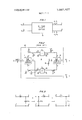
- FIG. I shows in block diagram, an in-phase hybrid coupler
- FIG. 2 shows a frequency-sensitive hybrid coupler comprising a pair of flat 3db couplers interconnected by means of a pair of dual networks;
- FIG. 3 shows an antimetric network
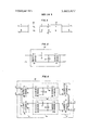
- FIG. 4 shows a tandem array of two in-phase couplers
- FIG. 5 shows a particular antimetric network
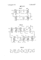
- FIG. 6 shows a specific in-phase, frequency-sensitive hybrid coupler
- FIGS. 7, 8 and 9 show various modifications of the coupler shown in FIG. 6;
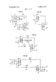
- FIG. 10 shows a flat in-phase hybrid coupler
- FIG. 11 shows the transposition of terminals to establish equivalency between couplers whose respective imaginary terms differ by degrees
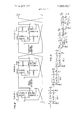
- FIG. 12 shows a tandem array of in-phase couplers for producing a signal division ratio of l p
- FIG. 13 shows a simplified coupler wherein the shunt inductors are incorporated into the core reactance of the transformers
- FIG. 14 shows an alternate embodiment of an inphase coupler using a different antimetric network
- FIG. 15 shows an array of couplers for dividing a sig nal into more than two components.
- FIG. 1 shows, in block diagram, an in-phase hybrid coupler 10 having two pairs of conjugate ports a-b and c-d. It is a characteristic of such couplers that an input signal v, applied to one port a of one pair of conjugate ports a-b, produces output signals v t, and v,k, at the other pair of conjugate ports and d, where t and k are, respectively, the coefficient of transmission and the coefficient of coupling for the coupler, and both are real numbers.
- an input signal v applied in port I produces output signals v k, and v 2, at ports 0 and d, respectively.
- an in-phase coupler such as the magic-T or hybrid transformer
- the coefficients k and r of an in-phase coupler are relatively independent of frequency over a broad frequency range.
- separate frequency sensitive networks external to the coupler.
- FIG. 2 shows a generalized hybrid coupler comprising a pair of flat 3db hybrid couplers 11 and 12, interconnected by means of a pair of frequency sensitive dual networks 13 and 14.
- Each of the hybrid couplers 11 and 12 is an in-phase coupler having two pairs of conjugate ports 1-2, and 3-4, where ports 1 and 2 are the antisymmetric ports and ports 3 and 4 are the symmetric ports. That is, a signal applied to port 1 will be divided equally, producing two in-phase output signals in ports 3 and 4. Similarly, an input signal applied to port 2 will also be divided equally. However, the resulting output signals at ports 3 and 4 will be 180 out of phase.
- ports a and b constitute one pair of conjugate ports of the overall coupler 20, and ports c and d constitute the second pair of conjugate ports.
- port b is shown terminated by means of a matching resistor 19.
- an input signal E applied to port 1 of input coupler 11 is divided into two equal, in-phase components El 2 at ports 3 and 4. Because networks 13 and 14 are dual networks, they have the same transmission coef'ficient r. Accordingly, they transmit equal signal components Er/ VTwhich combine in port 1 of output coupler 12 to produce a first output signal Er.
- the reflection coefficients of networks 13 and 14 have equal magnitudes but differ by 180. Accordingly, the reflected signal from network I3 is Ek/ V fwhereas the reflected signal from network 14 is Ek/ 2 Because of the above-noted properties of in-phase couplers, the reflected signals combine in port 2 of input coupler 11 to produce a second output signal Ek. No signal is coupled to port 2 of coupler 12.
- the circuit shown in FIG. 2 is a hybrid coupler whose coefficient of transmission I and whose coefficient of coupling k are fully defined by networks 13 and 14. Because the relative phases of k and r are arbitrary, coupler 20, as defined thus far, is neither a quadrature coupler nor an in-phase coupler. To fall into either of these two specific classes of couplers. it is necessary to define networks 13 and 14 further.
- any reactive two-port can be defined by a transfer matrix equation of the form E, A jB E,
- A, B, C and D are real and, in general, unequal; and E I, and E 1 are the input voltage and current, and the output voltage and current, respectively.
- the ratio of the reflection coefficient to the transmission coefficient for this network is I AjB its dual is given by l D jC jB A (4) That is, the transfer matrix of the dual network has the A D and B C terms interchanged.
- the We coupler can be defined by the following matrix equap p p +p tron. H6)
- k and t are the network coefficients, and are .couplers a tandem array 0f.tw0 or more couplers functions of frequency; if we recognize that the real portion of the product corand v v u and u, are the signal voltages at the couresponds i the major dlagona! terms i the p ports a b c and d respectively nary portion corresponds to the off-diagonal terms.
- a tandem array of z couplers can be as the ratio of polynominals, we obtain represented by the Scalar notation r Qr) f Qz) fi' Qr) u e+a m ...u,,.
- A is the common denominator of the I, and k synthesizing any given signal division ratio by means of functions.
- an array of in-phase couplers For purposes which will If, input voltages v, and v to coupler 20 are thembe explained hereinbelow, we select as one fundamenselves derived from a preceding in-phase coupler 30, such as is illustrated in FIG. 4, the relationship between the input signals g g to coupler 30 and the output sigtal two-port for this purpose, a network 40 shown in FIG. 5 comprising, in cascade: an Nsl turns ratio transformer 50; a series capacitor 51; a shunt inductance 52;
- the combined coupler is given by Since the resulting expression 1 01 in (35) is real, there is no signal division, and all of the input signal applied to the first coupler exits from a common port of the second coupler. Thus, the addition of these two couplers does not affect the net signal division ratio of the array. However, it does permit us to put the array function in the desired form.
- the desired P,,(() function and the desired Q,,() function are both polynomials of equal even degree n in C. It will be recalled, however, that it was noted that for the preferred basic network, the P and Q functions are of unequal degree in L.
- the net coupler array is now of the reduced form Z: +i) m. to orum].
- a specific coupler circuit incorporating the network illustrated in FIG. 5, will be considered.
- a pair of standard 3db transformer type hybrid couplers are used as the input and output couplers.
- input hybrid coupler 11 comprises a pair of ffzl turns ratio transformers 60 and 61 connected in the manner shown.
- Output coupler 12 similarly comprises a pair of V7.1 turns ratio transformers and 71, similarly connected.
- ports 1-2 and ports 3-4 constitute the two pairs of conjugate ports.
- a pair of antimetric networks 13 and 14 connect conjugate ports 3 and 4 of coupler 11 to a pair of conjugate ports 4 and 3 of the other coupler.
- the first of these networks 13, which connects port 3 of coupler 11 to port 4 of coupler 12, comprises, in cascade N:l turns ratio transformer 66; a shunt inductor 67 having an inductance L; a series capacitor 68 having a capacitance L; and an N:l turns ratio transformer 69.
- the second network 14 is the reverse of network 13 comprising, in cascade: a l:N turns ratio transformer 76; a series capacitor 77 having a capacitance L; a shunt inductor 78 having an inductance L; and a l:N transformer 79.
- the resulting circuit includes four pairs of transformers connected in cascade.
- these eight transformers can be replaced by four transformers, as illustrated in FIG. 7 where: transformers 60 and 66 are replaced by an V71 turns ratio transformer 80; transformers 61 and 76 are replaced by a l:N VT transformer 8]; transformers 69 and 71 are replaced by an N 2:l transformer 82; and transformers 79 and 70 are replaced by a l:N 2 turns ratio transformer 83.
- each of the networks 13 and 14 iden' tity sections comprising a pair of transformers having inverse turns ratio.
- N V211 turns ratio transformer 90 we add an N V211 turns ratio transformer 90, and a 1:N fiturns ratio transformer 91.
- N V 2':1 turns ratio transformer 93 we add an N V 2':1 turns ratio transformer 93, and 1:N 2 turns ratio transformer 94. It will be noted that in each case the net turns ratio of each pair of transformers is 1:1 and the networks are unaffected by their addition.
- Capacitor 104 is connected between a center tap on primary winding 110 of transformer 100 and one end of secondary winding 112 of transformer 101. The other end of winding 112 is grounded.
- Inductor 105 is connected in parallel with winding 112.
- capacitor 103 is connected between a center-tap on primary winding 111 of transformer 101 and one end of secondary winding 113 of transformer 100. The other end of winding 113 is grounded. Inductor 102 is connected in parallel with winding 113.
- the ends a-b and c-d of the primary windings of transformers 100 and 101 constitute the two pairs of conjugate ports of the resulting hybrid coupler.
- FIG. shows the flat coupler obtained when L becomes infmite.
- the resulting expression is now Factoring this expression, (i.e., solving for the roots of g and removing the common multiple 2, we obtain
- the first factor (1 i) represents a flat, 3db coupler for which
- the second factor for which corresponds to a coupler in which
- the third factor for which corresponds to a coupler in which L 0.7625 2N 1.3364 ZNL 1.0189 L/IZN 0.5706.
- a negative imaginary part is related to the manner in which the couple circuit was formulated. It will be recalled that the coupler matrix was given by couplers in the array, the resulting structure for producing an equivalent in-phase coupler having the assumed signal division ratio is shown in FIG. 12.
- Component coupler I in the array is a flat, 3db coupler having two pairs of conjugate ports 1-2 and 3-4. One pair of conjugate ports 3 and 4 are connected, respectively, to a pair of conjugate ports 1 and 2 of component coupler 2 in the array in a direct tandem connection. The sec ond pair of conjugate ports 3 and 4 of coupler 2 are, in turn, connected respectively to a pair of conjugate ports 2 and I of component coupler 3 in a transposed tandem connection.
- Port 1 of coupler l and port 3 of coupler 3 constitute a pair of conjugate ports ab of the resulting equivalent hybrid coupler
- Port 4 of coupler 3 and port 2 of coupler l constitute the second pair of conjugate ports c-d of the equivalent coupler.
- the inductor is in parallel with a transformer.
- the equivalent coupler has an assumed P to Q ratio given by l +12
- this coupler is intended to operate at the lower frequencies.
- at p it is a 3db coupler.
- the transformers must be designed to have a large core reactance at very low frequencies. It will be recognized that this is difficult to achieve.
- the present invention totally avoids the problem by merging the shunt inductor with the transformer, Specifically, the transformer is designed to have a core reactance that is equal to that of the shunt inductor. This greatly eases the transformer design problem and eliminates the shunt inductor as a discrete element.
- the coupler circuits can be further simplified as illustrated in FIG. 13. (It should be noted that a flat coupler, consisting of only transformers, can be designed to compensate for existing parasitics. However, these techniques cannot be readily used in the case of a frequency-sensitive coupler which includes components other than transformers.)
- the numerator of equation (50) In order for k/! to be imaginary, as required in a quadrature coupler, the numerator of equation (50) must be an odd polynomial in p, and the denominator an even polynomial in p; or vice versa. As such, the ratio is either zero or infinite at p 0.
- the k]: function is the ratio of two even order polynominals, such as It T (51 l where n and m are integers.
- H is equal to a 19,, at p 0, and can be made to have any desired value.
- the resulting form finally assumed by the component couplers depends upon the configuration of the basis antimetric network selected.
- the network of FIG. 5 which comprises a series capacitor and a shunt inductor
- the network of FIG. 3 including a series inductor and a shunt capacitor
- one possible form of the resulting component coupler would be as shown in FIG. 14.
- Such a circuit configura tion can be advantageously used to synthesize a high frequency coupler network. Since low-loss, high permeability materials are not readily available at the higher frequencies, transformers and 131 in FIG. 14 will have a large number of turns.
- the network capacitors 132 and 133 are in shunt with the transformers, the spurious capacitance can be included as part of the network capacitance.
- the network inductors 134 and 135 are in series with the transformer leakage inductance and, as such, can be included as part of the net work inductance.
- the transformers can be specifically designed to have a shunt capacitance equal to L/ZN and a leakage inductance equal to L/ZN thereby eliminating any need for discrete network capacitors and inductors. More generally, however, the transformer parasitics will be included as part of the network components and the magnitudes of the latter reduced accordingly.
- the specific couplers can be in-phase couplers, synthesized as explained hereinabove, or quadrature couplers, synthesized as explained in my U.S. Pat. No. 3,723,9l3, or mixtures of in-phase and quadrature couplers.
- any prescribed in-phase hybrid coupler signal division ratio k/r which varies as a function of frequency over a given frequency band of interest, can be synthesized by means of a tandem array of in-phase hybrid couplers.
- the simplest tandem array comprises two couplers, one of which has a signal division ratio that is constant over said band of interest and the other of which has a frequency sensitive signal division ratio over said band of interest which is different than said prescribed characteristic.
- a more complicated array will include two or more frequency sensitive couplers, and may also include one frequency insensitive coupler.
- the individual couplers in the array are arranged in ordered succession from first coupler to a last coupler by connecting the ports of one pair of conjugate ports of each coupler to the respective ports of one pair of conjugate ports of the next successive coupler in the arl iy appropriate preselection of the antimetric network, parasitics associated with the circuit components can be absorbed within the network, thus extending the operating frequency range.
- Two specific antimetric networks are illustrated.
- An in-phase hybrid coupler circuit having a prescribed overall signal division ratio which varies as a function of frequency over a given frequency band of interest comprising:
- tandem array of in-phase hybrid couplers at least one of which has a signal division ratio that varies as a function of frequency over said band of interest and is different from said prescribed signal division ratio.
- each coupler in said array has a signal division ratio that varies as a function of frequency over said band of interest and is different than said prescribed signal division ratio.
- each of said couplers having a signal division ratio which varies as a function of frequency comprises:
- first and second identical hybrid couplers whose signal division ratios are substantially constant over said frequency range of interest
- each of said first and second couplers having two pairs of conjugate ports
- said first antimetric network being connected between one port of one pair of conjugate ports of said first coupler and one port of one pair of conjugate ports of said second coupler;
- said second antimetric network being connected between the other port of said one pair of conjugate ports of said first coupler and the other port of said one pair of conjugate ports of said second coupler;
- said networks being further connected between said first and second couplers such that each is reverseconnected relative to the other.
- said one coupler comprises:
- first and second two-winding transformers each having a primary and a secondary winding
- each transformer being coupled to a center-tap along the primary winding of the other of said transformers by means of a series capacitor;
- each secondary winding being connected to a common function
- first inductor connected in parallel with the secondary winding of said first transformer
- second inductor connected in parallel with the secondary winding of said secondary transformer
- first and second inductors are discrete circuit components.
- said first and second inductors are the equivalent core inductors of said transformers.
- said one coupler comprises:
- first and second two-winding transformers each having a primary winding and a secondary winding
- one end of the secondary winding of each transformer being coupled to a center-tap along the primary winding of the other transformer by means of a series inductor;
- each secondary winding being connected to a common function
- An in-phase hybrid coupler circuit having a prescribed overall signal division ratio which varies as a function of frequency over a given frequency band of interest comprising:
- each of said couplers having a coupling coefficient between a first port and a second port equal to P,-/- A,-, and a coupling coefficient between a first port and a third port equal to A /A
- P is a polynomial function of the imaginary radian frequency p, and where A; is a polynomial containing all ofthe negative real portion roots of the normalizing polynomial jail lP l lP l 2 l? lP l
- said couplers arranged in ordered succession from a first coupler to said (n1) coupler by connecting the third port of each coupler to the first port of the next successive coupler in the array;
Landscapes
- Cable Transmission Systems, Equalization Of Radio And Reduction Of Echo (AREA)
- Networks Using Active Elements (AREA)
- Amplifiers (AREA)
Priority Applications (11)
| Application Number | Priority Date | Filing Date | Title |
|---|---|---|---|
| US466213A US3883827A (en) | 1974-05-02 | 1974-05-02 | Tandem arrays of in-phase couplers |
| CA217,604A CA1021080A (en) | 1974-05-02 | 1975-01-09 | Tandem arrays of in-phase couplers |
| SE7504645A SE400865B (sv) | 1974-05-02 | 1975-04-22 | Likfasig hybridkopplarkrets |
| DE19752518637 DE2518637A1 (de) | 1974-05-02 | 1975-04-26 | Gleichphasige hybridkopplerschaltung |
| JP50050838A JPS50147856A (enExample) | 1974-05-02 | 1975-04-28 | |
| BE155901A BE828533A (fr) | 1974-05-02 | 1975-04-29 | Arrangement en tandem de coupleurs en phase |
| AU80632/75A AU489999B2 (en) | 1975-04-29 | Improvements in or relating to hybrid coupler circuits | |
| IT22838/75A IT1037715B (it) | 1974-05-02 | 1975-04-29 | Circuito accoppiatore ibrido in fase |
| FR7513652A FR2269822B1 (enExample) | 1974-05-02 | 1975-04-30 | |
| NL7505159A NL7505159A (nl) | 1974-05-02 | 1975-05-01 | Hybridische koppelinrichting met in-fasige signaal-interrelatie. |
| GB18313/75A GB1493030A (en) | 1974-05-02 | 1975-05-01 | Hybrid coupler circuits |
Applications Claiming Priority (1)
| Application Number | Priority Date | Filing Date | Title |
|---|---|---|---|
| US466213A US3883827A (en) | 1974-05-02 | 1974-05-02 | Tandem arrays of in-phase couplers |
Publications (1)
| Publication Number | Publication Date |
|---|---|
| US3883827A true US3883827A (en) | 1975-05-13 |
Family
ID=23850937
Family Applications (1)
| Application Number | Title | Priority Date | Filing Date |
|---|---|---|---|
| US466213A Expired - Lifetime US3883827A (en) | 1974-05-02 | 1974-05-02 | Tandem arrays of in-phase couplers |
Country Status (10)
| Country | Link |
|---|---|
| US (1) | US3883827A (enExample) |
| JP (1) | JPS50147856A (enExample) |
| BE (1) | BE828533A (enExample) |
| CA (1) | CA1021080A (enExample) |
| DE (1) | DE2518637A1 (enExample) |
| FR (1) | FR2269822B1 (enExample) |
| GB (1) | GB1493030A (enExample) |
| IT (1) | IT1037715B (enExample) |
| NL (1) | NL7505159A (enExample) |
| SE (1) | SE400865B (enExample) |
Cited By (3)
| Publication number | Priority date | Publication date | Assignee | Title |
|---|---|---|---|---|
| US4263559A (en) * | 1979-01-26 | 1981-04-21 | Ford Aerospace & Communications Corp. | N-way series connected quadrature power divider and combiner |
| US9130653B2 (en) * | 2011-11-08 | 2015-09-08 | Filtronic Wireless Limited | Filter block and a signal transceiver comprising such a filter block |
| US20220285817A1 (en) * | 2021-03-02 | 2022-09-08 | U.S. Army Combat Capabilities Development Command, Army Research Laboratory | Hybrid coupler-based electrical power switches and power combining circuits using time folding using the same |
Citations (2)
| Publication number | Priority date | Publication date | Assignee | Title |
|---|---|---|---|---|
| US3452300A (en) * | 1965-08-11 | 1969-06-24 | Merrimac Research & Dev Inc | Four port directive coupler having electrical symmetry with respect to both axes |
| US3490054A (en) * | 1968-03-29 | 1970-01-13 | Bell Telephone Labor Inc | Power tempering of quadrature hybrid-coupled fan-outs |
-
1974
- 1974-05-02 US US466213A patent/US3883827A/en not_active Expired - Lifetime
-
1975
- 1975-01-09 CA CA217,604A patent/CA1021080A/en not_active Expired
- 1975-04-22 SE SE7504645A patent/SE400865B/xx unknown
- 1975-04-26 DE DE19752518637 patent/DE2518637A1/de not_active Withdrawn
- 1975-04-28 JP JP50050838A patent/JPS50147856A/ja active Pending
- 1975-04-29 IT IT22838/75A patent/IT1037715B/it active
- 1975-04-29 BE BE155901A patent/BE828533A/xx unknown
- 1975-04-30 FR FR7513652A patent/FR2269822B1/fr not_active Expired
- 1975-05-01 NL NL7505159A patent/NL7505159A/xx not_active Application Discontinuation
- 1975-05-01 GB GB18313/75A patent/GB1493030A/en not_active Expired
Patent Citations (3)
| Publication number | Priority date | Publication date | Assignee | Title |
|---|---|---|---|---|
| US3452300A (en) * | 1965-08-11 | 1969-06-24 | Merrimac Research & Dev Inc | Four port directive coupler having electrical symmetry with respect to both axes |
| US3514722A (en) * | 1965-08-11 | 1970-05-26 | Merrimac Research & Dev Inc | Networks using cascaded quadrature couplers,each coupler having a different center operating frequency |
| US3490054A (en) * | 1968-03-29 | 1970-01-13 | Bell Telephone Labor Inc | Power tempering of quadrature hybrid-coupled fan-outs |
Cited By (4)
| Publication number | Priority date | Publication date | Assignee | Title |
|---|---|---|---|---|
| US4263559A (en) * | 1979-01-26 | 1981-04-21 | Ford Aerospace & Communications Corp. | N-way series connected quadrature power divider and combiner |
| US9130653B2 (en) * | 2011-11-08 | 2015-09-08 | Filtronic Wireless Limited | Filter block and a signal transceiver comprising such a filter block |
| US20220285817A1 (en) * | 2021-03-02 | 2022-09-08 | U.S. Army Combat Capabilities Development Command, Army Research Laboratory | Hybrid coupler-based electrical power switches and power combining circuits using time folding using the same |
| US11764455B2 (en) * | 2021-03-02 | 2023-09-19 | The United States Of America As Represented By The Secretary Of The Army | Hybrid coupler-based electrical power switches and power combining circuits using time folding |
Also Published As
| Publication number | Publication date |
|---|---|
| GB1493030A (en) | 1977-11-23 |
| SE7504645L (sv) | 1975-11-03 |
| FR2269822A1 (enExample) | 1975-11-28 |
| AU8063275A (en) | 1976-11-04 |
| IT1037715B (it) | 1979-11-20 |
| BE828533A (fr) | 1975-08-18 |
| NL7505159A (nl) | 1975-11-04 |
| DE2518637A1 (de) | 1976-11-11 |
| JPS50147856A (enExample) | 1975-11-27 |
| CA1021080A (en) | 1977-11-15 |
| SE400865B (sv) | 1978-04-10 |
| FR2269822B1 (enExample) | 1978-02-24 |
Similar Documents
| Publication | Publication Date | Title |
|---|---|---|
| US3514722A (en) | Networks using cascaded quadrature couplers,each coupler having a different center operating frequency | |
| US2076248A (en) | Wave filter | |
| US5363072A (en) | High-frequency power divider-combiner | |
| RU2676192C1 (ru) | Сверхширокополосный фиксированный фазовращатель, основанный на ёмкостной нагрузке | |
| US2788496A (en) | Active transducer | |
| JPH07263993A (ja) | 電力合成器/分割器 | |
| US20160043701A1 (en) | Sub-network enhanced reflectionless filter topology | |
| US3919671A (en) | Digital filter | |
| US3551854A (en) | Variable equalizer | |
| US2115138A (en) | Wave transmission network | |
| US3883827A (en) | Tandem arrays of in-phase couplers | |
| US9859599B2 (en) | Bandstop filters with minimum through-line length | |
| US3895321A (en) | Minimum phase differential phase shifter | |
| US4158184A (en) | Electrical filter networks | |
| US3192490A (en) | Hybrid network having interconnected center tapped autotransformer windings | |
| US3605044A (en) | Filter structures using bimodal, bisymmetric networks | |
| US1849656A (en) | Transmission network | |
| US3449696A (en) | Dual section all pass lattice filter wherein nonlinearities of two sections cancel | |
| US3571767A (en) | Electrical filter arrangement | |
| US2249415A (en) | Wave filter | |
| Meng | Design and synthesis of lossy microwave filters | |
| US3879689A (en) | Matched phase shifter | |
| US3017584A (en) | Wave transmission network | |
| US3045194A (en) | Active multiport networks | |
| JP2002076703A (ja) | 分布定数フィルタ |