US3828862A - Travelling overhead carriage mining machine with articulated,tool carrying boom - Google Patents
Travelling overhead carriage mining machine with articulated,tool carrying boom Download PDFInfo
- Publication number
- US3828862A US3828862A US00291150A US29115072A US3828862A US 3828862 A US3828862 A US 3828862A US 00291150 A US00291150 A US 00291150A US 29115072 A US29115072 A US 29115072A US 3828862 A US3828862 A US 3828862A
- Authority
- US
- United States
- Prior art keywords
- arm
- mining machine
- carriage
- rails
- hydraulic ram
- Prior art date
- Legal status (The legal status is an assumption and is not a legal conclusion. Google has not performed a legal analysis and makes no representation as to the accuracy of the status listed.)
- Expired - Lifetime
Links
Images


Classifications
-
- E—FIXED CONSTRUCTIONS
- E21—EARTH DRILLING; MINING
- E21C—MINING OR QUARRYING
- E21C33/00—Trucks or other devices for transporting machines for slitting or completely freeing the mineral from the seam
-
- B—PERFORMING OPERATIONS; TRANSPORTING
- B61—RAILWAYS
- B61C—LOCOMOTIVES; MOTOR RAILCARS
- B61C11/00—Locomotives or motor railcars characterised by the type of means applying the tractive effort; Arrangement or disposition of running gear other than normal driving wheel
Definitions
- ABSTRACT A handling device such as a coal cutting tool in which a carriage is mounted on overhead rails for movement therealong and supports a depending articulated arm arrangement to which can be secured a tool such as an impact hammer. Means is provided for moving the articulated arm and hammer transversely, forwardly, upwardly and downwardly.
- This invention relates to handling devices especially but not exclusively for use underground such, for example, as in coal mines.
- a handling device comprising a carriage adapted to be suspended from and progressed along rail means and mounting articulated arm means to which can be attached a tool or other article to be handled or manipulated.
- the carriage comprises two relatively movable parts interconnected by fluid ram means with at least one of the parts having means for locking it relative to the rail means, the arrangement being such that the device is progressed along the rail means by locking said part to the rail means, extendingthe fluid ram means to advance said other part relative to the locked part, releasing the locking means, and retracting the fluid ram means which causes the previously locked part to be pulled towards the advanced part.
- the device can be progressed along the rail means by a walking action.
- both parts are provided with locking means so that either carriage part is lockable to the rails then the carriage by appropraite locking and action of the interconnecting fluid rams can be advanced or retreated along the rail means.
- a support arrangement for location underground and along which a carriage can be progressed, the support arrangement comprising a plurality of colliery arches or equivalent supports with a rail bridging adjacent arches, the rail being secured to each arch by a support bracket assembly of pivotal construction such that the rail can pivot transversely of the arch and oscillate relative thereto.
- longitudinally aligned rails are slightly spaced apart at their adjacent ends and are connected to the support bracket assembly by flat plates or links.
- FIG. 1 is a side elevation of a handling device according to the invention
- FIG. 2 is a corresponding rear elevation
- FIG. 3 is a perspective view of the carriage construction
- FIG. 4 is a fragmentary transverse sectional view of the carriage
- FIG. 5 is a fragmentary longitudinal sectional view of the carriage
- FIGS. 6 and 7 are respectively side and front elevations of the rail support arrangements.
- the rails 22 may be supported on the arches 21 in any convenient manner but a preferred support arrangement is illustrated particularly in FIGS. 6 and 7.
- the rails 22 can pivot bodily transversely of the arches 21 and also take up different heights relative to the ground due to the oscillatory character of the flat plates or links 29. This means that the rails 22 will follow any ground settlement which occurs.
- the rails 22 can be of any convenient cross-sectional shape, for example I-section (as shown) and can be of integral or fabricated construction.
- a similar hydraulic lock or brake is provided at each side of the leading end of the front carriage part 35 for gripping, when actuated, the corresponding rail 22.
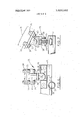
- Bracket arms 45 depend from the front carriage part 35 and mount a shaft 46 oscillatable via a rack-andthe arm 51 while a second hydraulic ram 54 interconnects the arm 51 and the adjacent end of the arm 52.
- the arm 52 detachably carries a cradle 55 which slidably mounts the hammer 20.
- a third hydraulic ram 56 interconnects the arm 52 and the cradle 55.
- a hydraulic ram 57' interconnects the cradle 55 and hammer and serves to slide the latter relative to the cradle 55.
- the ram 56 interconnects the arm 52 and a link extending from the arm 52 adjacent its tool engaging end. This link is pivotally connected to the hammer by a strut which can be replaced by struts of different lengths, or be length adjustable, to suit different hammers.
- the hammer 20 can thus, relative to the carriage 35, 37 be oscillated transversely, projected forwardly, moved rearwardly and disposed in any attitude between substantially vertical and substantially horizontal. Moreover, the hammer 20 can be advanced and withdrawn relative to the cradle.
- the carriage part 37 is hydraulically locked to the rails 22, the carriage rams 41 are extended which advances the carriage part along the rails 22 relative to the carriage part 37, the hydraulic locks 43 are released, and the carriage rams 39 are retracted thus pulling the carriage part 37 along after the carriage 35.
- both carriage parts 35 and 37 are provided with hydraulic locks or clamps then it will be manifest that either carriage part can be locked to the rails 22 so that Lil the carriage by appropriate locking and actuation of 40 the rams 41 can be advanced or retracted along the rails 22.
- the carriage is locked in position on the rails 22 by the hydraulic locks 43 when the hammer 20 is in operatron.
- a control valve bank 58 for controlling the device and hammer 20 is carried by the rear carriage part 37 from a depending arm 59 rearwardly inclined relative to the carriage and being pivotal about a vertical axis so that the controls can be located at any convenient location of a semi-circular arc rearwardly of the carriage and hammer 20.
- valves 63 control the cylinder 53, the swing cylinders 49, the cradle cylinder 47, the travel cylinders 39, the lock or clamp cylinders 43, the cylinder 54 and the cylinder56. Appropriate relief valving is provided.
- the pumps 60 are in communication with an oil reservoir 65.
- the hammer 20 has ,a water spray 66 associated with it, the spray feed pipe 67 incorporating a shut-off valve 68.
- Convenient lighting 69 for illumination purposes is provided at the front of the carriage.
- a mining machine comprising:
- a carriage assembly constituted by a front carriage part and a rear carriage part
- hydraulic ram means interconnecting the carriage parts for effecting relative rectilinear movement therebetween
- releasable hydraulically-operated clamping means adjacent the trailing end of the rear carriage part for locking the latter to the rails, means for selectively operating the hydraulic ram means and the releasable hydraulically-operated clamping means to effect movement of the carriage along the rails,
- adjustable articulated arm means suspended from the shaft for carrying and presenting a tool to earth strata to be mined.
- each carriage part is a box section with the hydraulic ram means protectively housed in the front carriage part.
- a mining machine as claimed in claim 1 in which the oscillatable shaft mounts a pinion in mesh with a rack reciprocable by two hydraulic rams, one at each side, to oscillate the shaft.
- a mining machine as claimed in claim 1 in which the articulated arm means comprises a first arm pivotally connected to a bracket on the oscillatable shaft and pivotally connected to a second arm intermediate the ends thereof, a first hydraulic ram interconnecting the braket and first arm, and a second hydraulic ram interconnecting the first arm and the adjacent end of the second arm.
- a mining machine as claimed in claim 4 in which the second arm pivotally mounts a cradle and a third hydraulic ram interconnects the cradle and the second arm at a location remote from the pivotal connection therebetween.
- a mining machine as claimed in claim 5 in which the cradle slidably mounts an impact hammer movable relative to the cradle under the action of a fourth hydraulic ram connected between the cradle and the hammer.
- a mining machine as claimed in claim 6 further comprising an arm depending from and movable with the carriage assembly, and a control unit mounted on the arm for operating the hydraulic rams and hydraulically-operated clamping means.
- a mining machine as claimed in claim 7 in which the depending arm is rearwardly inclined relative to the carriage assembly and is pivotable about a vertical axis.
- a mining machine as claimed in claim 1 in which the rails comprise a pair of parallel rails secured to a plurality of colliery arches, each rail being constituted by a number of sections each bridging adjacent arches with each rail secured to each arch by a support breacket assembly of pivotal construction such that each rail can pivot transversely of the arch and oscillate 11.
- a mining machine as claimed in claim 9 in which relative thereto. longitudinally aligned rails are slightly spaced apart at 10.
- a mining machine as claimed in claim 9 in which their adjacent ends and are connected to the support each pair of parallel rail sections are interconnected by bracket assembly by a fiat plate. a transverse spacer. 5
Landscapes
- Engineering & Computer Science (AREA)
- Mechanical Engineering (AREA)
- Mining & Mineral Resources (AREA)
- Life Sciences & Earth Sciences (AREA)
- General Life Sciences & Earth Sciences (AREA)
- Geochemistry & Mineralogy (AREA)
- Geology (AREA)
- Transportation (AREA)
- Excavating Of Shafts Or Tunnels (AREA)
- Lining And Supports For Tunnels (AREA)
- Bridges Or Land Bridges (AREA)
- Supports For Pipes And Cables (AREA)
Abstract
A handling device such as a coal cutting tool in which a carriage is mounted on overhead rails for movement therealong and supports a depending articulated arm arrangement to which can be secured a tool such as an impact hammer. Means is provided for moving the articulated arm and hammer transversely, forwardly, upwardly and downwardly.
Description
United States Patent [191 Dabell et a1.
[11] 3,828,862 Aug. 13, 1974 Appl. No.: 291,150
Assignee:
[30] Foreign Application Priority Data Sept. 22, 1971 Great Britain 44134/71 July 15, 1972 Great Britain 33245/72 [52] US. Cl. 173/43, 61/45 R, 248/251,
299/30, 299/33, 299/70, 212/26 [51] Int. Cl Elq 3/03 [58] Field of Search... 173/22, 23, 31, 32, 43;
[56] References Cited UNITED STATES PATENTS 3,040,677 6/1962 Creedle 105/31 3,470,969 10/1969 Arcangeli 173/43 3,476,193 11/1969 Stromnes 173/43 3,731,976
5/1973 Granskog et al 299/18 Primary Examiner-Ernest R. Purser Attorney, Agent, or Firm-Sughrue, Rothwell, Mion, Zinn & Macpeak [57] ABSTRACT A handling device such as a coal cutting tool in which a carriage is mounted on overhead rails for movement therealong and supports a depending articulated arm arrangement to which can be secured a tool such as an impact hammer. Means is provided for moving the articulated arm and hammer transversely, forwardly, upwardly and downwardly.
11 Claims, 8 Drawing Figures ;;\\\x y \\5 2| /ZI 2 4o 39 4o 43 H 4b 5Q 45 45 F 53 55 5| a": s.
mm 5 i 4 I/ 52 5s "58 PAIENIEB AUGI 3:914
sum 1 or 6 35mm v This invention relates to handling devices especially but not exclusively for use underground such, for example, as in coal mines.
According to the present invention there is provided a handling device comprising a carriage adapted to be suspended from and progressed along rail means and mounting articulated arm means to which can be attached a tool or other article to be handled or manipulated.
Preferably, the carriage comprises two relatively movable parts interconnected by fluid ram means with at least one of the parts having means for locking it relative to the rail means, the arrangement being such that the device is progressed along the rail means by locking said part to the rail means, extendingthe fluid ram means to advance said other part relative to the locked part, releasing the locking means, and retracting the fluid ram means which causes the previously locked part to be pulled towards the advanced part. Thus, the device can be progressed along the rail means by a walking action.
If both parts are provided with locking means so that either carriage part is lockable to the rails then the carriage by appropraite locking and action of the interconnecting fluid rams can be advanced or retreated along the rail means. j
Also according to the present invention there is provided a support arrangement for location underground and along which a carriage can be progressed, the support arrangement comprising a plurality of colliery arches or equivalent supports with a rail bridging adjacent arches, the rail being secured to each arch by a support bracket assembly of pivotal construction such that the rail can pivot transversely of the arch and oscillate relative thereto.
There is preferably a pair of parallel rails between adjacent arches, each mounted as defined in the preceding paragraph with the rails of each pair interconnected adjacent each arch by a transverse spacer.
Preferably also, longitudinally aligned rails are slightly spaced apart at their adjacent ends and are connected to the support bracket assembly by flat plates or links.
A support arrangement as defined above obviates or mitigates any misalignment of the rails which might be caused by ground settlement.
An embodiment of the present invention will now be described, by way of example, with reference to the accompanying drawings, in which:
FIG. 1 is a side elevation of a handling device according to the invention;
FIG. 2 is a corresponding rear elevation;
FIG. 3 is a perspective view of the carriage construction;
FIG. 4 is a fragmentary transverse sectional view of the carriage;
FIG. 5 is a fragmentary longitudinal sectional view of the carriage;
FIGS. 6 and 7 are respectively side and front elevations of the rail support arrangements; and,
FIG. 8 is a hydraulic circuit of the handling device.
The handling device illustrated is used underground in a coal mine, the device being employed to manipulate a hydraulic impact hammer 20.
In the mine heading which is supported by conventional colliery arches 21 or steel joists or other supports, there is supported by the arches at the top two side-by-side parallel rails 22 along which the handling device is to be progressed.
The rails 22 may be supported on the arches 21 in any convenient manner but a preferred support arrangement is illustrated particularly in FIGS. 6 and 7.
Two parallel lengths of rail 22 bridge adjacent arches 21 and consecutive rails 22 are spatially interconnected at each colliery arch 21 by a support bracket assembly 23 (FIGS. 6 and 7).
Each support bracket assembly 23 comprises a support plate 24 which is clamped to the arch 21 at the desired location by bolting 25, the plate 24 having a pair of depending lugs 26 between which is pivotally mounted the stem 27 of a depending fork 28 between which is pivotally secured a pair of flat plates or links 29. The arrangement is such that the fork 28 is pivotal transversely of its arch 21 about axis 30 while the flat plates or links 29 extend longitudinally of the arch 21 and can oscillate about a pivot axis 31 which is centrally intermediate the ends thereof. Consecutive rails are secured to the flat plate or link. The rails 22 of each pair are spatially interconnected adjacent each arch 21 by a transverse tube or pipe 32.
From the above it will be manifest that the rails 22 can pivot bodily transversely of the arches 21 and also take up different heights relative to the ground due to the oscillatory character of the flat plates or links 29. This means that the rails 22 will follow any ground settlement which occurs.
The rails 22 can be of any convenient cross-sectional shape, for example I-section (as shown) and can be of integral or fabricated construction.
The device comprises a carriage 33 comprising a front carriage part 35 and a rear carriage part 37 interconnected by double-acting hydraulic rams 39. The carriage parts 35 and 37 are of box girder construction as can be seen in FIGS. 3 to 5 and have slides 40 by means of which they are suspended via a suspension 41 from the rails 22. The double-acting hydraulic rams 39 are substantially housed in the front carriage part 35 as can be seen for protective purposes. A double-acting hydraulic lock or clamp 43 is carried by each side of the trailing end of the rear carriage part 37 for gripping, when actuated, the corresponding rail 22 to prevent movement of the rear carriage part 37 relative to the rails 22.
In a modified arrangement a similar hydraulic lock or brake is provided at each side of the leading end of the front carriage part 35 for gripping, when actuated, the corresponding rail 22.
The carriage may alternatively comprise two aligned U-shaped parts with the limbs of one part slidable inside the limbs of the other part, there being a hydraulic ram between each aligned pair of limbs of the carriage parts. The carriage parts are suspended from the rails by slides, and at least one of the carriage parts is provided with a means (hydraulic and/or mechanical) for securing same to the rails.
The arm 52 detachably carries a cradle 55 which slidably mounts the hammer 20. A third hydraulic ram 56 interconnects the arm 52 and the cradle 55. A hydraulic ram 57'interconnects the cradle 55 and hammer and serves to slide the latter relative to the cradle 55. Alternatively, the ram 56 interconnects the arm 52 and a link extending from the arm 52 adjacent its tool engaging end. This link is pivotally connected to the hammer by a strut which can be replaced by struts of different lengths, or be length adjustable, to suit different hammers.
The hammer 20 can thus, relative to the carriage 35, 37 be oscillated transversely, projected forwardly, moved rearwardly and disposed in any attitude between substantially vertical and substantially horizontal. Moreover, the hammer 20 can be advanced and withdrawn relative to the cradle.
To advance the device and hammer 20 along the rails 22, the carriage part 37 is hydraulically locked to the rails 22, the carriage rams 41 are extended which advances the carriage part along the rails 22 relative to the carriage part 37, the hydraulic locks 43 are released, and the carriage rams 39 are retracted thus pulling the carriage part 37 along after the carriage 35.
If both carriage parts 35 and 37 are provided with hydraulic locks or clamps then it will be manifest that either carriage part can be locked to the rails 22 so that Lil the carriage by appropriate locking and actuation of 40 the rams 41 can be advanced or retracted along the rails 22.
The carriage is locked in position on the rails 22 by the hydraulic locks 43 when the hammer 20 is in operatron.
A control valve bank 58 for controlling the device and hammer 20 is carried by the rear carriage part 37 from a depending arm 59 rearwardly inclined relative to the carriage and being pivotal about a vertical axis so that the controls can be located at any convenient location of a semi-circular arc rearwardly of the carriage and hammer 20.
A power pack 62, hammer 20-and hydraulic circuitry of the device is shown in FIG. 8. The power pack 62 houses pumps 60 driven by a motor 61. Control valve bank 58 consists of control valves 63, preferably lever operated as indicated at 64.
These valves 63 control the cylinder 53, the swing cylinders 49, the cradle cylinder 47, the travel cylinders 39, the lock or clamp cylinders 43, the cylinder 54 and the cylinder56. Appropriate relief valving is provided.
The pumps 60 are in communication with an oil reservoir 65.
The hammer 20 has ,a water spray 66 associated with it, the spray feed pipe 67 incorporating a shut-off valve 68.
What is claimed is:
l. A mining machine, comprising:
a. a carriage assembly constituted by a front carriage part and a rear carriage part,
b. means on each carriage part for movablyengaging overhead rails,
c. hydraulic ram means interconnecting the carriage parts for effecting relative rectilinear movement therebetween,
d. releasable hydraulically-operated clamping means adjacent the trailing end of the rear carriage part for locking the latter to the rails, means for selectively operating the hydraulic ram means and the releasable hydraulically-operated clamping means to effect movement of the carriage along the rails,
e. depending bracket means mounted on the front carriage part,
f. an oscillatable shaft supported on the bracket means parallel with the rails, and
g. adjustable articulated arm means suspended from the shaft for carrying and presenting a tool to earth strata to be mined.
2. A mining machine as claimed in claim 1 in which each carriage part is a box section with the hydraulic ram means protectively housed in the front carriage part.
3. A mining machine as claimed in claim 1 in which the oscillatable shaft mounts a pinion in mesh with a rack reciprocable by two hydraulic rams, one at each side, to oscillate the shaft.
4. A mining machine as claimed in claim 1 in which the articulated arm means comprises a first arm pivotally connected to a bracket on the oscillatable shaft and pivotally connected to a second arm intermediate the ends thereof, a first hydraulic ram interconnecting the braket and first arm, and a second hydraulic ram interconnecting the first arm and the adjacent end of the second arm.
5. A mining machine as claimed in claim 4 in which the second arm pivotally mounts a cradle and a third hydraulic ram interconnects the cradle and the second arm at a location remote from the pivotal connection therebetween.
6. A mining machine as claimed in claim 5 in which the cradle slidably mounts an impact hammer movable relative to the cradle under the action of a fourth hydraulic ram connected between the cradle and the hammer.
7. A mining machine as claimed in claim 6 further comprising an arm depending from and movable with the carriage assembly, and a control unit mounted on the arm for operating the hydraulic rams and hydraulically-operated clamping means.
8. A mining machine as claimed in claim 7 in which the depending arm is rearwardly inclined relative to the carriage assembly and is pivotable about a vertical axis.
9. A mining machine as claimed in claim 1 in which the rails comprise a pair of parallel rails secured to a plurality of colliery arches, each rail being constituted by a number of sections each bridging adjacent arches with each rail secured to each arch by a support breacket assembly of pivotal construction such that each rail can pivot transversely of the arch and oscillate 11. A mining machine as claimed in claim 9 in which relative thereto. longitudinally aligned rails are slightly spaced apart at 10. A mining machine as claimed in claim 9 in which their adjacent ends and are connected to the support each pair of parallel rail sections are interconnected by bracket assembly by a fiat plate. a transverse spacer. 5
Claims (11)
1. A mining machine, comprising: a. a carriage assembly constituted by a front carriage part and a rear carriage part, b. means on each carriage part for movably engaging overhead rails, c. hydraulic ram means interconnecting the carriage parts for effecting relative rectilinear movement therebetween, d. releasable hydraulically-operated clamping means adjacent the trailing end of the rear carriage part for locking the latter to the rails, means for selectively operating the hydraulic ram means and the releasable hydraulically-operated clamping means to effect movement of the carriage along the rails, e. depending bracket means mounted on the front carriage part, f. an oscillatable shaft supported on the bracket means parallel with the rails, and g. adjustable articulated arm means suspended from the shaft for carrying and presenting a tool to earth strata to be mined.
2. A mining machine as claimed in claim 1 in which each carriage part is a box section with the hydraulic ram means protectively housed in the front carriage part.
3. A mining machine as claimed in claim 1 in which the oscillatable shaft mounts a pinion in mesh with a rack reciprocable by two hydraulic rams, one at each side, to oscillate the shaft.
4. A mining machine as claimed in claim 1 in which the articulated arm means comprises a first arm pivotally connEcted to a bracket on the oscillatable shaft and pivotally connected to a second arm intermediate the ends thereof, a first hydraulic ram interconnecting the braket and first arm, and a second hydraulic ram interconnecting the first arm and the adjacent end of the second arm.
5. A mining machine as claimed in claim 4 in which the second arm pivotally mounts a cradle and a third hydraulic ram interconnects the cradle and the second arm at a location remote from the pivotal connection therebetween.
6. A mining machine as claimed in claim 5 in which the cradle slidably mounts an impact hammer movable relative to the cradle under the action of a fourth hydraulic ram connected between the cradle and the hammer.
7. A mining machine as claimed in claim 6 further comprising an arm depending from and movable with the carriage assembly, and a control unit mounted on the arm for operating the hydraulic rams and hydraulically-operated clamping means.
8. A mining machine as claimed in claim 7 in which the depending arm is rearwardly inclined relative to the carriage assembly and is pivotable about a vertical axis.
9. A mining machine as claimed in claim 1 in which the rails comprise a pair of parallel rails secured to a plurality of colliery arches, each rail being constituted by a number of sections each bridging adjacent arches with each rail secured to each arch by a support breacket assembly of pivotal construction such that each rail can pivot transversely of the arch and oscillate relative thereto.
10. A mining machine as claimed in claim 9 in which each pair of parallel rail sections are interconnected by a transverse spacer.
11. A mining machine as claimed in claim 9 in which longitudinally aligned rails are slightly spaced apart at their adjacent ends and are connected to the support bracket assembly by a flat plate.
Applications Claiming Priority (2)
| Application Number | Priority Date | Filing Date | Title |
|---|---|---|---|
| GB4413471A GB1380405A (en) | 1971-09-22 | 1971-09-22 | Earth working machines |
| GB3324572A GB1425014A (en) | 1972-07-15 | 1972-07-15 | Support arrangement for a carriage |
Publications (1)
| Publication Number | Publication Date |
|---|---|
| US3828862A true US3828862A (en) | 1974-08-13 |
Family
ID=26261783
Family Applications (1)
| Application Number | Title | Priority Date | Filing Date |
|---|---|---|---|
| US00291150A Expired - Lifetime US3828862A (en) | 1971-09-22 | 1972-09-21 | Travelling overhead carriage mining machine with articulated,tool carrying boom |
Country Status (4)
| Country | Link |
|---|---|
| US (1) | US3828862A (en) |
| JP (1) | JPS4872002A (en) |
| DE (1) | DE2246338A1 (en) |
| FR (1) | FR2154245A5 (en) |
Cited By (16)
| Publication number | Priority date | Publication date | Assignee | Title |
|---|---|---|---|---|
| US4049317A (en) * | 1975-02-03 | 1977-09-20 | Gewerkschaft Eisenhutte Westfalia | Tunnel driving apparatus |
| US4232849A (en) * | 1978-04-11 | 1980-11-11 | Atlas Copco Aktiebolag | Drill boom arrangement |
| US4260297A (en) * | 1978-09-26 | 1981-04-07 | Edbro Limited | Machines for positioning roof supports in a tunnel |
| US4280771A (en) * | 1977-11-25 | 1981-07-28 | Friedrich Wilh. Schwing Gmbh | Apparatus for distributing concrete, especially in the shuttering of gallery linings in mine and tunnel workings |
| US4303275A (en) * | 1978-12-15 | 1981-12-01 | Coal Industry (Patents) Limited | Slideway means and excavating machines comprising slideway means |
| DE3045047A1 (en) * | 1980-11-29 | 1982-07-01 | Gewerkschaft Eisenhütte Westfalia, 4670 Lünen | DEVICE FOR MAKING HANGING AND / OR SHOCK BORE IN UNDERGROUND SPACES, ESPECIALLY IN CUTTING AND EXTRACTION OPERATIONS |
| US4591128A (en) * | 1984-08-02 | 1986-05-27 | Karlichek Gregory J | Tool reaction balancing mechanism |
| US4600171A (en) * | 1984-10-12 | 1986-07-15 | Lockheed Corporation | Aircraft stores vertical extension and retraction system |
| US4687375A (en) * | 1983-08-20 | 1987-08-18 | Anderson Strathclyde Plc | Circular heading machine |
| US4792110A (en) * | 1987-07-31 | 1988-12-20 | Bond Irvin D | Tooling support apparatus with linear boom |
| US4818025A (en) * | 1986-11-14 | 1989-04-04 | Hecla Mining Company | Narrow opening mechanical miner |
| US5199510A (en) * | 1991-05-22 | 1993-04-06 | Baker Hughes Incorporated | Raise boring head and stem assembly method |
| US5582467A (en) * | 1995-04-10 | 1996-12-10 | Centre De Recherche Industrielle Du Quebec | Displaceable working apparatus with extensible boom |
| EP1807607A1 (en) * | 2004-11-03 | 2007-07-18 | Atlas Copco Rock Drills AB | Boom arrangement for a scaling device and scaling device |
| US20150232280A1 (en) * | 2012-09-10 | 2015-08-20 | Bulk Solutions Pty Ltd | Roof Mountable Support System |
| US20160097279A1 (en) * | 2013-05-14 | 2016-04-07 | Minrail Inc. | Mining site having a shallow angle extraction shaft, shallow angle mining method and method for constructing a penstock |
Families Citing this family (9)
| Publication number | Priority date | Publication date | Assignee | Title |
|---|---|---|---|---|
| JPS5060979A (en) * | 1973-10-06 | 1975-05-26 | ||
| JPS546991Y2 (en) * | 1973-12-19 | 1979-04-03 | ||
| JPS5345982B2 (en) * | 1974-04-27 | 1978-12-11 | ||
| DE2462542C3 (en) * | 1974-08-05 | 1984-10-25 | Gewerkschaft Eisenhütte Westfalia, 4670 Lünen | Part-cut driving machine for driving tunnels, galleries or other routes |
| DE2437669C3 (en) | 1974-08-05 | 1978-04-27 | Gewerkschaft Eisenhuette Westfalia, 4670 Luenen | Driving device for driving tunnels, galleries and routes |
| DE2753670C2 (en) * | 1977-12-02 | 1984-02-09 | Tamrock (Deutschland) GmbH, 4300 Essen | Device for the production of face boreholes when driving mining routes and the like. |
| JPS54175796U (en) * | 1978-05-31 | 1979-12-12 | ||
| AT391348B (en) * | 1988-12-29 | 1990-09-25 | Boehler Pneumatik Int Gmbh | CONTROL VALVE FOR A COUNTERBACK STITCH HOLE DRILL |
| DE4335753C2 (en) * | 1993-10-20 | 1998-07-09 | Schaeff Karl Gmbh & Co | Hydraulically driven excavator for a jacking device for underground driving |
-
1972
- 1972-09-21 US US00291150A patent/US3828862A/en not_active Expired - Lifetime
- 1972-09-21 DE DE2246338A patent/DE2246338A1/en active Pending
- 1972-09-22 JP JP47094644A patent/JPS4872002A/ja active Pending
- 1972-09-22 FR FR7233794A patent/FR2154245A5/fr not_active Expired
Cited By (19)
| Publication number | Priority date | Publication date | Assignee | Title |
|---|---|---|---|---|
| US4049317A (en) * | 1975-02-03 | 1977-09-20 | Gewerkschaft Eisenhutte Westfalia | Tunnel driving apparatus |
| US4280771A (en) * | 1977-11-25 | 1981-07-28 | Friedrich Wilh. Schwing Gmbh | Apparatus for distributing concrete, especially in the shuttering of gallery linings in mine and tunnel workings |
| US4232849A (en) * | 1978-04-11 | 1980-11-11 | Atlas Copco Aktiebolag | Drill boom arrangement |
| US4260297A (en) * | 1978-09-26 | 1981-04-07 | Edbro Limited | Machines for positioning roof supports in a tunnel |
| US4303275A (en) * | 1978-12-15 | 1981-12-01 | Coal Industry (Patents) Limited | Slideway means and excavating machines comprising slideway means |
| DE3045047A1 (en) * | 1980-11-29 | 1982-07-01 | Gewerkschaft Eisenhütte Westfalia, 4670 Lünen | DEVICE FOR MAKING HANGING AND / OR SHOCK BORE IN UNDERGROUND SPACES, ESPECIALLY IN CUTTING AND EXTRACTION OPERATIONS |
| US4448263A (en) * | 1980-11-29 | 1984-05-15 | Gewerkschaft Eisenhutte Westfalia | Drilling apparatus |
| US4687375A (en) * | 1983-08-20 | 1987-08-18 | Anderson Strathclyde Plc | Circular heading machine |
| US4591128A (en) * | 1984-08-02 | 1986-05-27 | Karlichek Gregory J | Tool reaction balancing mechanism |
| US4600171A (en) * | 1984-10-12 | 1986-07-15 | Lockheed Corporation | Aircraft stores vertical extension and retraction system |
| US4818025A (en) * | 1986-11-14 | 1989-04-04 | Hecla Mining Company | Narrow opening mechanical miner |
| US4792110A (en) * | 1987-07-31 | 1988-12-20 | Bond Irvin D | Tooling support apparatus with linear boom |
| US5199510A (en) * | 1991-05-22 | 1993-04-06 | Baker Hughes Incorporated | Raise boring head and stem assembly method |
| US5582467A (en) * | 1995-04-10 | 1996-12-10 | Centre De Recherche Industrielle Du Quebec | Displaceable working apparatus with extensible boom |
| EP1807607A1 (en) * | 2004-11-03 | 2007-07-18 | Atlas Copco Rock Drills AB | Boom arrangement for a scaling device and scaling device |
| EP1807607A4 (en) * | 2004-11-03 | 2014-11-19 | Atlas Copco Rock Drills Ab | Boom arrangement for a scaling device and scaling device |
| US20150232280A1 (en) * | 2012-09-10 | 2015-08-20 | Bulk Solutions Pty Ltd | Roof Mountable Support System |
| US20160097279A1 (en) * | 2013-05-14 | 2016-04-07 | Minrail Inc. | Mining site having a shallow angle extraction shaft, shallow angle mining method and method for constructing a penstock |
| US10196072B2 (en) * | 2013-05-14 | 2019-02-05 | Minrail Inc. | Mining site having a shallow angle extraction shaft, shallow angle mining method and method for constructing a penstock |
Also Published As
| Publication number | Publication date |
|---|---|
| DE2246338A1 (en) | 1973-03-29 |
| FR2154245A5 (en) | 1973-05-04 |
| JPS4872002A (en) | 1973-09-28 |
Similar Documents
| Publication | Publication Date | Title |
|---|---|---|
| US3828862A (en) | Travelling overhead carriage mining machine with articulated,tool carrying boom | |
| RU2391512C2 (en) | Support section of room-and-pillar development system with pillar extraction in reverse order | |
| CN111425216B (en) | Composite supporting structure, construction system and method | |
| CN104695871A (en) | Drilling boom device of two-boom hydraulic rock bolt drilling carriage | |
| CN107965342A (en) | Arched tunnel driving moves into covering device certainly without support repeatedly | |
| CN205206825U (en) | Tunneling, anchoring and protection integrated machine | |
| CN102434154A (en) | Development machine-mounted anchor rod drilling rig | |
| CN105587328B (en) | One kind suspension mining multi-arm roofboltier of beam type | |
| CN109723445A (en) | Parallel three steps full section of tunnel entirety driving method | |
| CN106677813A (en) | Novel temporary supporting device for coal mine roadway comprehensive digging face | |
| CN106703853A (en) | Repeated-free-support temporary support equipment | |
| CN201363144Y (en) | Development machine piggyback temporary support | |
| SU1597112A3 (en) | Machine for setting support in entry driving | |
| CN202673317U (en) | Onboard temporary support machine | |
| CN210768786U (en) | Rocker arm type tunneling machine | |
| CN207847625U (en) | Rectangular shaped roadways driving moves into covering device certainly without support repeatedly | |
| CN102748051B (en) | Onboard temporary support machine | |
| CN203008944U (en) | Comprehensive fore support for excavation head | |
| US6079504A (en) | Underground mining drill rig with safety interlock | |
| CN207847670U (en) | Arched tunnel driving moves into covering device certainly without support repeatedly | |
| CN204532119U (en) | A kind of drill boom device of two-arm hydraulic anchor rod drill carriage | |
| SU927128A4 (en) | Powered roof support section | |
| CN204511432U (en) | A kind of four drill boom formula pick anchor all-in-ones | |
| CN209799865U (en) | Roadway excavation of taking extending structure is with boring dress anchor all-in-one | |
| CN108425690B (en) | Self-moving net, anchor and protection integrated support |