US3805507A - Apparatus for stopping spindle assemblies of a textile yarn processing machine in a predetermined position - Google Patents
Apparatus for stopping spindle assemblies of a textile yarn processing machine in a predetermined position Download PDFInfo
- Publication number
- US3805507A US3805507A US00264816A US26481672A US3805507A US 3805507 A US3805507 A US 3805507A US 00264816 A US00264816 A US 00264816A US 26481672 A US26481672 A US 26481672A US 3805507 A US3805507 A US 3805507A
- Authority
- US
- United States
- Prior art keywords
- spindle assembly
- yarn
- tension roll
- lever
- roll
- Prior art date
- Legal status (The legal status is an assumption and is not a legal conclusion. Google has not performed a legal analysis and makes no representation as to the accuracy of the status listed.)
- Expired - Lifetime
Links
- 230000020347 spindle assembly Effects 0.000 title claims abstract description 304
- 239000004753 textile Substances 0.000 title claims abstract description 47
- 230000003111 delayed effect Effects 0.000 claims abstract description 53
- 230000015572 biosynthetic process Effects 0.000 claims abstract description 29
- 241001589086 Bellapiscis medius Species 0.000 claims description 11
- 239000012530 fluid Substances 0.000 claims description 7
- 238000009987 spinning Methods 0.000 claims description 5
- 230000000694 effects Effects 0.000 claims description 4
- 244000182067 Fraxinus ornus Species 0.000 claims description 2
- 230000007246 mechanism Effects 0.000 description 60
- 230000008878 coupling Effects 0.000 description 10
- 238000010168 coupling process Methods 0.000 description 10
- 238000005859 coupling reaction Methods 0.000 description 10
- 230000003213 activating effect Effects 0.000 description 1
- 230000001419 dependent effect Effects 0.000 description 1
- 238000010586 diagram Methods 0.000 description 1
- 238000012544 monitoring process Methods 0.000 description 1
- 230000002028 premature Effects 0.000 description 1
- 239000000837 restrainer Substances 0.000 description 1
- 230000000452 restraining effect Effects 0.000 description 1
- 238000013022 venting Methods 0.000 description 1
Images


Classifications
-
- D—TEXTILES; PAPER
- D01—NATURAL OR MAN-MADE THREADS OR FIBRES; SPINNING
- D01H—SPINNING OR TWISTING
- D01H7/00—Spinning or twisting arrangements
- D01H7/02—Spinning or twisting arrangements for imparting permanent twist
- D01H7/04—Spindles
- D01H7/22—Braking arrangements
- D01H7/2208—Braking arrangements using mechanical means
- D01H7/2233—Braking arrangements using mechanical means by suppressing the driving means, e.g. by declutching
- D01H7/2241—Braking arrangements using mechanical means by suppressing the driving means, e.g. by declutching the belt being moved off the driven whorl
- D01H7/225—Braking arrangements using mechanical means by suppressing the driving means, e.g. by declutching the belt being moved off the driven whorl and the spindle being braked simultaneously
Definitions
- ABSTRACT spindle assembly of a textile yarn processing machine in a predetermined position and responsive to a predetermined condition of yarn breakage and/or the formation of a full package of processed yarn.
- the textile yarn processing machine includes rotatable spindle assemblies each having a whorl portion for rotating thereof and a brake for stopping rotation thereof, a drive belt for driving the whorl portions and pivoting tension rolls for holding the drive belt in tight engagement with the whorl portions for normal rotation thereof in a first position and movable to a second position for holding the drive belt in loose engagement with the whorl portion for allowing stopping of the spindle assembly and for slight rotation of the spindle assembly.
- the apparatus for stopping the spindle assemblies in' a predetermined position includes yarn feelers actuated by the predetermined yarn condition,
- the yarn feelers for deactuating the brake after a predetermined time delay for allowing the slight rotation of the spindle assemblies by the loose engagement of the drive belt, and spindle assembly stop devices for stopping rotation of the spindle assembly in the predetermined position after the time delay of the time delayed devices and during the slight rotation of the spindle assembly following deactuation of the spindle brake.
- This invention relates to the improvement of automatic means responsive to a predetermined condition of yarn breakage and the formation of a full package of processed yarn for stopping rotation of a spindle assembly of a textile yarn processing machine, such as a twister, spinning frame or the like, in a predetermined position.
- a textile yarn processing machine such as a twister, spinning frame or the like, having a plurality of rotatable spindle assemblies for processing of yarn and forming a package of processed yarn.
- each spindle assembly includes a whorl portion for effecting rotation thereof and a brake means for stopping rota tion thereof, a tangential drive belt means engaging the whorl portions of the spindle assemblies for causing rotation thereof, and pivotally mounted tension roll means associated with each of the spindle assemblies for holding the drive belt in tight driving engagement with the whorl portion for normal rotation of the spindle assembly in a first position thereof and movable to a second position for holding the drive belt in loose engagement with the whorl portion of the spindle assembly for allowing stopping of the spindle assembly and for slight rotation of the spindle assembly.
- the automatic means for stopping rotation of the spindle assembly in a predetermined position upon yarn breakage and/or the formation of a full package of processed yarn includes yarn feeler means actuated by the predetermined yarn condition, means operatively connected between the yarn feeler means and the spindle assembly brake means for'actuating the brake means to stop rotation of the spindle assembly upon actuation of the yarn feeler means, tension roll control means operatively connected with the yarn feeler means for causing movement of the tension roll means to the second position upon actuation of the yarnfeeler means for allowing stopping of the spindle assembly, time delayed means operatively connected with the yarn feeler means and the brake actuating means and responsive to actuation of the yarn feeler means for deactivating the brake eans after a predetermined time delay for allowing the slight rotation of the spindle assembly by the loose engagement of the drive belt, and spindle assembly stop means operatively associated with the spindle assembly and the time delayed means for stopping rotation of the spindle assembly in the predetermined position after the predetermined time
- the spindle assembly stop means also include suitable means for allowing tension to build up in the yarn upon restarting of the spindle assembly before activating of the yarn feeler devices and the spindle as sembly brake means so as to prevent actuation of the yarn feeler devices during start up.
- these spindle assembly stop mechanisms include a combination of electrical and mechanical devices.
- the automatic means for stopping rotation of the spindle assembly in a predetermined position includes yarn feeler means comprising a first electrical switch engaging the yarn as it passes from the spindle assembly to the package roll for actuation when yarn breakage occurs and a second electrical switch contacting the surface of the package of yarn on the package roll for actuation upon the formation of a full package of processed yarn.
- the automatic means further includes electrical circuit means operatively connected between the yarn feeler switches and the spindle assembly brake means for actuating the brake means to stop rotation of the spindle assembly upon actuation of either of the yarn feeler switches.
- This preferred embodiment includes a tension roll control means comprising a lever mounted for pivotal movement medially thereof and carrying the tension roll means on one end thereof for movement between the first and second positions, means biasing the lever means and the tension roll means in the second position of the tension roll means, movable stop means operatively associated with the otherend of the lever means and solenoid operated latch means operatively associated with the stop means and the electrical circuit means for holding the stop means against the other end of the lever means to hold the lever means and the tension roll means in the first position of the tension roll means and responsive to actuation of the electrical circuit means by either of the yarn feeler switches to move out of latching engagement with the stop means for allowing the levermeans, the tension roll means and the stop means to move under the influence of the biasing means to the second position of the tension roll means.
- This preferred embodiment of automatic means for stopping rotation of the spindle assembly in a predetermined position further includes time delayed means comprising a fluid controlled, compressible and expandable bellows means operatively connected with the tension roll lever means for .compressing during movement of the lever means and the tension roll means from the first position to the second position for delaying the time of movement a predetermined amount, and a switch means disposed in the electrical circuit means and operatively connected to the bellows means for deactuation to deactuate the electrical circuit after the time delayed movement of the tension roll means to the second position for deactuating the brake means after a predetermined time delay for allowing the slight rotation of the spindle assembly by the loose engagement of the drive belt.
- time delayed means comprising a fluid controlled, compressible and expandable bellows means operatively connected with the tension roll lever means for .compressing during movement of the lever means and the tension roll means from the first position to the second position for delaying the time of movement a predetermined amount
- a switch means disposed in the electrical circuit means
- This preferred embodiment further includes spindle assembly stop means comprising a projection secured to and extending from the tension roll control lever means for movement with the lever means into close proximity with the whorl portion of the spindle assembly when the tension roll means moves to the second position, and a projection secured to and extending from the whorl portion of the spindle assembly for contact with the projection on the lever means when the lever means and the tension roll means have moved to the second position of the tension roll means after the time delay is effected by the time delayed means to stop rotation of the spindle assembly in a predetermined position.
- the embodiment further includes means operatively associated with the time delayed means and the yarn package drive roll for stopping operation of the drive roll upon actuation of either of the yarn feeler switch means and after the predetermined time delay.
- a second preferred embodiment of automatic means for stopping rotation of the spindle assembly in a predetermined position includes yarn feeler means comprising a first electrical switch engaging the yarn as it passes from the spindle assembly to the package roll for actuation when breakage occurs and a second electrical switch contacting the surface of the package of yarn on the package roll for actuation upon the formation of a full package of processed yarn.
- This automatic means further includes means operatively connected between the yarn feeler switches and the spindle assembly brake means for actuating the brake means to stop rotation of the spindle assembly upon actuation of either of the yarn feeler switches.
- the spindle assembly brake actuating means comprises an electrical circuit connected with the yarn feeler switches for actuation when either of the switches is actuated, a motor connected with the electrical circuit for actuation when the electrical circuit is actuated, a first circular rotating cam driven by the motor and having an outer and inner camming surface on its circumference, a cam follower for successively engaging the camming surfaces and a brake actuating lever means connected to the cam follower for actuating the spindle assembly brake means when the cam follower is in engagement with the inner camming surface and for deactuating the brake means when the cam follower is in engagement with the outer camming surface.
- This second preferred embodiment further includes tension roll control means comprising a second circular rotating cam driven by the motor and having an outer, a central and an inner camming surface on its circumference, a lever mounted for pivotal movement medially thereof and carrying the tension roll means on one end thereof for movement between the first and second positions, means biasing the lever means and the tension roll means in the second position of the tension roll means, a cam follower disposed on the other end of the lever means for successively engaging the camming surfaces on the second cam and for holding the lever means and the tension roll means in the first position of the tension roll means during engagement with the outer camming surface and for allowing movement of the lever means and the tension roll means to the second position of the tension roll means under the influence of the biasing means during engagement with the central camming surface for allowing stopping of the spindle assembly.
- tension roll control means comprising a second circular rotating cam driven by the motor and having an outer, a central and an inner camming surface on its circumference, a lever mounted for pivotal movement medially thereof and carrying the tension
- Time delayed means are provided in this second preferred embodiment which are operatively connected with the yarn feeler switches and the brake actuating means and are responsive to actuation of either of the yarn feeler switches for deactuating the brake means after a predetermined time delay for allowing the slight rotation of the spindle assembly by the loose engagement of the drive belt.
- the time delayed means comprises the first cam and the inner and outer camming surfaces being mounted for rotation relative to the second cam and the camming surfaces thereon so that the outer camming surface of the first cam comes into engagement with the cam follower of the brake actuating lever for deactuating the spindle assembly brake means while the cam follower on the tension roll control lever is in engagement with the central camming surface on the second cam for holding the tension roll means in the second position for allowing slight rotation of the spindle assembly by the loose engagement of the drive belt.
- This second preferred embodiment further includes spindle assembly stop means comprising a spindle assembly stop lever connected with the tension roll control lever for movement therewith and having a projection secured to and extending from the spindle stop lever, a projection secured to and extending from the whorl portion of the spindle assembly for contact with the projection on the stop lever for stopping the spindle assembly in the predetermined position when the cam follower on the tension roll control lever moves into engagement with the inner camming surface on the second cam means and after the predetermined time delay of the time delayed means and during the slight rotation of the spindle assembly following deactuation of the spindle brake means.
- This embodiment also includes a third circular rotating cam driven by the motor and having an outer and inner camming surface on the periphery thereof and an electrical switch means positioned for engagement by the camming surfaces of the third cam and actuated when one of the camming surfaces comes into engagement with the switch means.
- This switch means is operatively connected with the drive roll for the yarn package for stopping operation of the drive roll upon actuation of the switch means.
- a fourth circular rotating cam driven by the motor means and having outer and inner camming surfaces on its circumference is provided. An electrical switch is in contact with the fourth cam for actuation thereby when one of the inner or outer camming surfaces comes into engagement with the switch. This switch is connected to the motor for stopping operation of the motor and rotation of all of the cams when the spindle assembly has been stopped in the predetermined position.
- FIG. 3 is a view, like FIG. 1, showing the spindle assembly stopping means in the condition occurring upon the breakage of yarn or the formation of a full package of processed yarn and with the spindle assembly stopped in a predetermined position;
- FIG. 4 is a view, like FIGS. 2 and 3, illustrating the spindle assembly stopping means in the condition occurring immediately after restarting of rotation of the spindle assembly and during the build up of sufficient tension in the yarn to prevent actuation of the spindle assembly brake by the yarn feeler means due to insufficient tension in the yarn;
- FIG. 5 is a perspective view of generally the mechanical components of the first embodiment of the spindle assembly stopping means illustrated in FIGS. 2-4;
- FIG. 6 is a diagrammatic, schematic, wiring diagram of a second embodiment of a spindle assembly stopping means in accordance with this invention and shown in the condition of operation of the spindle assembly during normal yarn processing and prior to the occurrence of yarn breakage of the formation of a full package 0 processed yarn;
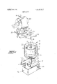
- FIG. 7 is a sectional plan view through a portion of the second embodiment of FIG.'6.
- FIG. 8 is a plotted time-distance study for the second embodiment of the spindle assembly stopping means illustrated in FIGS. 6 and 7.
- FIG. 1 a schematic, perspective view of a single spindle assembly station of a textile yarn 2-for-l twister machine. lt is to be understood, that a plurality of these spindle assembly stations are provided in which the spindle assembly stations are arranged side-by-side in two'rows along the outsides of the machine. For purposes of this application, only one spindle assembly station will be described.
- the spindle assembly station broadly includes a spindle assembly, generally indicated at 10, comprising a rotatably driven rotor mechanism, generally indicated at 11, which includes a whorl portion 12 suitably rotatably mounted on a portion of the twister machine frame 13 and'rotated by a continuous, tangential, drive belt 14 in a manner well understood by those with ordinary skill in the art.
- Tension rolls 15 are associated with each spindle assembly and are pivotally mounted for engaging and holding the drive belt 14 in tight driving engagement with the whorl portion 12 for normal rotation of the rotor mechanism 11 of the spindle assembly 10 in a first position of the tension roll 15.
- the tension rolls are movable to a second position for holding the drive belt 14 in loose engagement with the whorl portion 12 for allowing stopping of the rotor mechanism 11 of the spindle assembly 10 and for allowing slight rotation of the rotor mechanism 1 1 of the spindle assembly 10.
- the spindle assembly 10 further includes a carrier mechanism 18 for carrying a package 16 of yarn Y and being rotatably mounted on the rotor mechanism 11 so that the rotor mechanism may rotate relative thereto while the carrier mechanism is maintained in stationary position.
- the carrier mechanism includes a basket herein inasmuch as these complete details are not necessary for an understanding of the present invention.
- yarn Y is withdrawn from the package 16 and is threaded through the various mechanisms for twisting or processing of the yarn.
- the yarn Y emerges from the rotor mechanism 11 at the end of channel 20 and forms a balloon of yarn Y around the package 16 and around the basket device 19.
- a hollow balloon restrainer mechanism 22 is mounted around the above described mechanisms of the spindle assembly 10 and around the rotating balloon of yarn Y.
- the yarn Y is then led from the spindle assembly 10 through a pigtail guide 24, around a pre-take-up roller 25 and to a traversing device 26 from which it is wound onto a package roll 27 carrying a suitable bobbin or carrier for receiving the traversely wound yarn Y after it has been twisted or processed and for forming a package 28 of the twisted or processed yarn Y.
- the package roll 27 is driven or rotated by a drive roll 29 frictionally contacting the surface of the package 28 of yarn You the package roll 27 for rotatably driving same.
- the drive roll 29 is driven by shaft 30 to which it is magnetically or otherwise coupled.
- the rotor mechanism 11 of the spindle assembly 10 includes a suitable brake device for stopping rotation of the rotor mechanism 11 of the spindle assembly 10 when formation of a full package of processed yarn 28 is formed or upon the occurrence of a break in the yarn Y.
- these brake mechanisms have normally been manually operated and details of such prior manually operated brake mechanism may be seen in assignees prior U.S. Pat. No.-
- means generally indicated at 32 are provided for automatically stopping rotation of the spindle assembly 10 in a predetermined position in which the rotor mechanism 1 1 and the yarn Y emerging from the channel 20 faces the outside of the machine for servicing by an operator upon the occurrence of yarn breakage or the formation of a full package of processed yarn.
- This spindle assembly stopping means 32 is generally disposed below the spindle assembly 10, as shown in FIG. 1.
- yarn feeler means in the form of a first electrical switch 35 engaging the moving yarn Y in any suitable position as it passes from the spindle assembly 10 to the package roll 27 and constructed for closing or actuation upon the breakage of the yarn Y.
- the yarn feeler means further include a second electrical switch 36 contacting the surface of the package 28 of processed yarn Y on the package roll 27 and constructed for closing or actuation upon the formation of a full package 28 of processed yarn Y.
- FIGS. 2-5 of the drawing a first preferred embodiment of the automatic spindle assembly stopping means is illustrated.
- an electrical circuit in the form of lines 37, 38, 39, 40, 41 lead from the respective switches 35 and 36 and close an electrical circuit from bus bars 42 and 43 through an electrically operated brake mechanism 44 for the rotor mechanism 11 of the spindle assembly 10.
- the brake device 44 may be any suitable electrically actuated brake.
- the tension roll 15 is pivotally mounted at 50 on one end of a swing lever 51 which is swingable about a fixed fulcrum 52.
- a linearly movable stop shaft 54 bears at one end against the other end of the lever 51 and in normal operating position (FIG. 2), holds the other end of the lever 51 against a fixed stop 55 for holding of the lever 51 and the tension roll 15 in the first position of the tension roll 15 which holds the drive belt 14 in tight engagement with the whorl 12 of the rotor mechanism 11.
- the stop shaft 54 is held in this position by a pivoted latch device 57 which engages teeth 58 on the stop shaft 54.
- the latch mechanism 57 is pivotally mounted for moving out of engagement with the teeth 58 upon actuation of a solenoid 60.
- the solenoid 60 is connected with the above described electrical circuit by lines 61 leading from line 40 and line 62 leading from line 41 for actuation when the electrical circuit is actuated by closing of either of the yarn feeler switches 35 or 36.
- the solenoid 60 is actuated to move the latch 57 out of engagement with the teeth 58 on the stop rod 54.
- the tension roll control lever 51 is biased by a spring 63 so that when the latch 57 is disengaged from the teeth 58, the tension roll control lever 51 and the tension roll 15 will move under the bias of the spring 63 to the second position of the tension roll 15 (as shown in FIG. 3) which holds the drive belt 14 in light contact with the whorl portion 12 of the rotor mechanism 11.
- This movement of the tension roll control lever 51 will also cause the other end thereof to move against the stop shaft 54 pushing the stop shaft 54 downwardly (as viewed in FIG. 3) and outwardly from the front of the yarn processing machine (as shown in FIG. 1).
- the spindle assembly stopping means further includes a time delayed means comprising a fluid controlled, compressible and expandable bellows mechanism 70 fixed at one end 71 and attached at the other end to a lagging lever 72.
- the lagging lever 72 is fulcrummed at the tension roll control lever fulcrum 52 for movement with the tension roll control lever 51 as the tension roll control lever 51 and the tension roll 15 move from the first position to the second position of the tension roll 15 (from the position shown in FIG. 2 to the position shown in FIG. 3).
- the bellows device 70 slowly contracts by pushing air or other fluid out of an outlet line 74 which includes a monitoring valve 75 therein to provide a predetermined time delay in the movement of the levers 51 and 72.
- the bellows mechanism includes a lever 103 attached to the lever 51 which suitably contacts a control handle of the valve mechanism for venting of the bellows mechanism 70 after the predetermined time delayed movement.
- a switching lever 77 is connected with the lever 72 at one end thereof and includes a bifurcated portion at the other end thereof carrying pins 78 and 79 which are engaged in slots 80 and 81 of camming devices 82 and 83, respectively.
- the camming device 82 is in engagement with a cam follower 84 attached to one end of the switch 45 so that as the lever 77 moves with the lever 72, the pin 78 will ride in the slot 80 until it bottoms in the slot 80 and then moves the camming device 82 such that the cam follower 84 moves onto a portion of the surface of the camming device 82 allowing the switch 45 to break the circuit leading to the spindle assembly brake mechanism 44 by breaking the circuit between lines 39 and 40 (as shown in FIG. 3).
- a spring biased projection 85 which extends outwardly therefrom and is pivotally mounted thereon for movement between the stop pins 86 and 87.
- the projection 85 comes into close proximity with the whorl portion 12 of the rotor mechanism 11 of the spindle assembly 10.
- a cooperating stop projection 88 is secured to the whorl portion 12 of the spindle assembly 10 and as the whorl portion 12 is slightly rotated under the influence of the loose contact of the drive belt 14, the projection 88 comes in contact with the projection 85 and the rotor mechanism 11 of the spindle assembly 10 is stopped in the predetermined position in which the channel 20 from which the yarn Y emerges from the rotor mechanism 1 1 faces the outside of the machine for servicing by an operator.
- a line 100 leads from the switch 45 and to a line 101 connected with lighted signal devices 102 and connected with bus bar 43 such that when the switch 45 is moved by the camming device 82 to the position (FIG. 3) for breaking the circuit to the brake device 44, it will close the circuit to the signal lights 102 lighting these lights up for indication to an operator that servicing of the spindle assembly is needed.
- the spindle assembly 10 has now been stopped in a predetermined position and an operator may service a broken yarn Y or doff a full package 28 of processed yarn Y.
- the stop shaft 54 may be manually pushed inwardly to move the other end of the tension roll control lever 51 against the stop 55 (as shown in FIG. 4) which moves the tension roll back to the first position thereof for holding the drive belt 15 in tight engagement with the whorl 12 of the rotor mechanism 11 of the spindle assembly 10 for normal rotation thereof.
- the lever 72 lags behind the lever 51 due to the time delayed bellows mechanism 70 (as shown in FIG.
- the camming device 83 has again momentarily closed the circuit to the magnetic or other coupling of drive roll 29 thus actuating the drive roll 29,for rotation to drive the package roll 27.
- the circuit to the signal lights 102 has been broken and they are cut off. Since the solenoid 60 is deactuated, the latch mechanism 57 are in engagement with the teeth 58 on the stop rod 54 for holding the lever 51 and the tension roll 15 in the first position of the tension roll. If desired, a suitable holding circuit for the solenoid 60 may be employed for holding the latch 57 out of engagement with the teeth 58 until restarting of the spindle assembly 10.
- FIG. 5 The generally mechanical components of the above described first embodiment of spindle assembly stopping mechanism, may be seen in FIG. 5.
- FIGS. 6-8 of the drawings a second preferred embodiment of the automatic spindle assembly stopping means 32 is illustrated.
- like reference numerals are utilized for components which are the same as that of the first embodiment illustrated in FIGS. 2-5 and described above.
- the yarn feeler switches 35 and36 are electrically connected'from bus bar 42 with an electrical circuit including line 39 which leads to switch 152 which connects with a line 153 to a motor 111 which has a line 51 leading therefrom to bus bar 43.
- the motor 111 includes a drive shaft 112 upon which is mounted a first circular rotating cam 115 having an outer camming surface 115a and an inner camming surface l15b on its circumference or periphery.
- a cam follower 117 successively engages the camming surfaces a and 115b of the cam 115 and is attached to one end of a brake lever 118 which is pivotally mounted between brake shoes 119 and on the inside of the whorl 12 of the rotor mechanism 111 of the spindle assembly 10.
- the brake lever 118 will move under the influence of spring 122 for wedging apart the brake shoes 119 and 120 for braking the rotor mechanism 11 of the spindle assembly 10.
- the brake mechanism 119, 120 for the spindle assembly 10 is disengaged.
- the tension roll 15 is also controlled by a lever 51 which is fulcrummed at 17 and carries the tension roll 15 on one end thereof.
- tension roll control lever 51 On the other end of tension roll control lever 51 is a follower which engages a second circular rotating cam 127 mounted on motor saft 112 and which has an outer camming surface 127a, a central camming surface 127b and an inner camming surface 127C.
- the lever 51 is biased for engagement by the follower 125 with the cam 127 by a spring 63.
- the lever 51 and tension roll 15 are disposed in the first position of the tension roll 15 holding the belt 14 in tight engagement with the whorl portion 12 of the spindle assembly 10 for normal driving.
- the rotating cam 127 movesto a position that the follower 125 rides down onto the central camming surface 127b and the inner camming surface 1270, the lever 51 and tension roll 15 move to the second position of the tension roll 15 so as to hold the drive belt l4v in loose engagement with the whorl portion 12 of the spindle assembly 10 for allowing braking of the spindle assembly 10 and slight rotation of the rotor mechanisms 11 of the spindle assembly 10 after braking.
- the first cam 115 and the camming surfaces 115a and 115b are mounted in the shaft 112 of the motor 110 relative to the mounting of the second cam 127 and the camming surfaces 127a, 127b and 1276 such that the cam follower 125 comes into engagement with the central camming surface 127b of the cam 127 for movement of the tension roll 15 from its first position to its second position, while simultaneously, the cam follower 117 on the brake actuating lever 118 moves into engagement with the inner camming surface llSb on the cam 1 15 for actuating the brake 1 19, 120 to stop rotation of the rotor mechanism 11 of the spindle assembly I0.
- the cam follower 117 moves onto the outer camming surface 115a of the first cam 1 15 to deactuate the brake 119 and 120, while the follower 125 on the tension roll control lever 51 moves into engagement with the inner camming section 127c of the cam 127 to allow for slight rotation of the rotor mechanism 11 of the spindle assembly 10 by the tension roll 15 holding the belt 14 in loose engagement with the whorl portion 12 of the spindle assembly 10.
- a lever 130 is mounted for movement with the lever 51 and includes on the forward end thereof a similar spring biased projection 85 which extends outwardly therefrom and is pivotally mounted thereon for movement between stop pins 86 and 87.
- the projection 85 comes into close proximity with the whorl portion 12 of the rotor mechanism 11 of the spindle assembly 10.
- a cooperating stop projection 88 is secured to the whorl portion 12 of the spindle assembly 10 and as the whorl portion 12 is slightly rotated under the influence of the loose contact of the drive belt 14, the projection 88 comes into contact with the projection 85 and the rotor mechanism 11 of the spingle assembly 10 is stopped in a predetermined position in which the channel 20 from which the yarn Y emerges from the rotor mechanism 1 1 faces the outside of the machine for servicing by an operator.
- the motor shaft 1 12 is also provided with a third circular rotating cam 140 having inner and outer cam surfaces on the periphery thereof and which contact an electrical switch 95 which is disposed in a circuit comprising lines 96 leading from line 41, line 97 which leads to the magnetic or other coupling of drive roll 29 and line 98 which leads from the coupling of drive roll 29 to bus bar 42.
- the cam 140 is positioned on the motor shaft 112 for actuating the switch 95 and deactuating the coupling to the drive roll 29 when the spindle assembly is stopped.
- a fourth circular rotating cam 150 is disposed on the motor shaft 112 and includes inner and outer camming surfaces in engagement with the electrical switch 152, described above.
- the switch 152 is arranged for deactuation by the cam 150 to stop operation of the motor 11 1 upon engagement of the stop projections 85 and 88 and thereby stop rotation of the cams 115, 127, 140 and 150.
- a fifth rotating cam 160 is provided with inner and outer cam surfaces which engage an electrical switch 45.
- the electrical switch 45 when actuated by the cam 160 completes a circuit through lines 162 to the line 101 which is connected with bus bar 43 and through line 162 which connects with bus bar 42 for lighting of the signal lights 102.
- a push shaft switch 54 is provided which is disposed in an electrical line 171 to the motor 111 and which connects with the line 153 to bypass the switch 152 so that when the push rod 54 is pushed against the bias of a spring 170, electrical current will be supplied to the motor 11 for rotating the shaft 112 and the other cams, described above.
- the outer cam section 127a in the same way as the outer cam section 1150, is made sufficiently long that a sufficient thread tension holding the yarn feeler switch 35 open can be built up.
- the switch 152 which is acted upon by the cam 150, the feeding of current to the motor 111 is again interrupted while the switch 45 is actuated by the cam 160 to extinguish the signal light 102.
- the stopping mechanism is then in position for another stopping cycle, as descirbed above.
- FIG. 8 there is shown a time distance study which shows more clearly the course of the individual operations described above and the various cam surfaces.
- On the ordinate there has been plotted the time in seconds, it being assumed that the cams rotate once by 360 in 9.4 seconds after the occurrence of a break in the yarn or the formation of a full package of processed yarn.
- the time interval between 6 and 6' seconds has been left blank and indicates the time at which the cam motor is stopped before actuation upon restarting of the motor.
- the first or top function plotted is that of actuation of the yarn feeler switches, either the switch 35 which detects a break in the yarn or the switch 36 which detects the formation of a full package of yarn. It is noted that the yarn feeler switches are disconnected shortly after the eighth second, when a sufficient thread tension is reached upon the restarting of the spindle assembly and the starting of the drive roll.
- the next function plotted is that of the spindle brake cam and illustrates the outer cam surface 1150 at which time the brake is disengaged and the inner cam surface ll5b at which time the brake is engaged.
- the sloped portion of the cam from the inner cam surface 115b to the outer cam surface 115a is the time during which disengagement of thebrake is effected.
- the belt tension roll cam 127 is next plotted and shows the outer cam surface 127a, the central cam surface 127b and the inner cam surface 1270.
- the outer cam surface 127a is the portion in which the tension roll holds the drive belt in tight frictional engagement with the whorl portion of the spindle assembly for normal rotation of the spindle assembly.
- the central cam section 127b and inner cam section are the portions in which the tension roll is moved to its second position for holding the drive belt in light frictional engagement with the whorl portion of the spindle assembly for allowing braking of the spindle assembly and for slight rotation of the spindle assembly following disengagement of the brake for stopping of the spindle assembly in the predetermined position.
- the inner cam surface 1270 indicates the time during which the spindle assembly is stopped in its predetermined position.
- the motor cam is next plotted and the inner cam surface indicates the time during which the switch for supplying current to the motor is disengaged.
- the signal light cam and the outer cam surface indicates the time during which the signal light is lighted.
- the drive roll cam 140 and the outer cam surfaces indicate the times during which current is supplied to the coupling of the drive roll for disengaging the coupling to the drive roll and then for engaging the coupling of the drive roll.
- the time during which the drive roll is rotatmg is plotted.
- this invention has provided automatic means responsive to a predtermined condition of yarn breakage and the formation of a full package of processed yarn for stopping rotation of a spindle assembly of a textile yarn processing machine, such as a twister, spinning frame or the like, in a predetermined position.
- a textile yarn processing machine such as a twister, spinning frame or the like
- a textile yarn processing machine such as a twister, spinning frame or the like, having a plurality of rotatable spindle assemblies for processing of yarn and forming a package of processed yarn and each including a whorl portion for effecting rotation thereof and a brake means for stopping rotation thereof, a tangential drive belt means engaging said whorl portions of said spindle assemblies for causing rotation thereof, and pivotally mounted tension roll means associated with each of said spindle assemblies for holding saiddrive belt in tightdriving engagement with said whorl portion for normal rotation of said spindle assembly in a first position thereof and movable to a second position for holding said drive belt in loose engagement with said whorl portion of said spindle assembly for allowing stopping of said spindle assembly and for slight rotation of said spindle assembly; the improvement of automatic means responsive to a predetermined condition of yarn breakage and/or the formation of a full package of processed yarn for stopping rotation of said spindle assembly in a predetermined position, said means comprisyarn feeler means actuated by
- time delayed means operatively connected with said yarn feeler means and said brake actuating means and responsive to actuation of said yarn feeler means for deactuating said brake means after a predetermined time delay for allowing the slight rotation of the spindle assembly by the loose engagement of the drive belt;
- spindle assembly stop means operatively associated with said spindle assembly and said time delayed means for stopping rotation of said spindle assembly in the predetermined position after the predetermined time delay of said time delayed means and during the slight rotation of said spindle assembly following deactuation of said spindle assembly brake means.
- said time delayed means includes means for maintaining said spindle assembly brake means deactuated for a predetermined time after said tension roll means has been moved back to said first position for restarting normal rotation of said spindle assembly to insure that sufficient tension has been built up in the yarn being processed by said spindle assembly to avoid actuation of said yarn feeler means during start up.
- said yarn feeler means includes an electrical switch means
- said spindle assembly brake actuating means comprises an electrical circuit connected between said yarn feeler switch means and said spindle assembly brake means.
- said tension roll control means comprises a lever means mounted for pivotal movement medially thereof and carrying said tension roll means on one end thereof for movement between said first and second positions, menas biasing said lever means and said tension roll means in the second position of said tension roll means, movable stop means operatively associated with the other end of said lever means for holding said lever means and said tension roll means in said first position of said tension roll means and for movement away from the other end of said lever means for allowing movement of said lever means and said tension roll means to the second position of said tension roll means under the influence of said biasing means, and solenoid operated latch means operatively associated with said stop means and said electrical circuit means for holding said stop means against the other end of said lever means to hold said lever means and said tension roll means in the first position of said tension roll means and responsive to actuation of said electrical circuit means by said feeler means to move out of latching engagement with said stop means for allowing said lever means and said tension roll means to move under the influence of said biasing
- said time delayed means comprises a fluid controlled, compressible and expandable bellows means operatively connected with said lever means for compressing during movement of said lever means and said tension roll means from said first position to said second position of said tension roll means for delaying the time of movement a predetermined amount.
- said spindle assembly stop means comprises a projection secured to and extending from said lever means for movement with said lever means into close proximity with said whorl portion of said spindle assembly when said tension roll means moves to said second position, and a projection secured to and extending from said whorl portion of said spindle assembly for contact with said projection on said lever means when said lever means and said tension roll means have moved to said second position of said tension roll means after the time delay effected by said time delayed means to stop rotation of said spindle assembly in the predetermined position.
- each of said spindle assemblies includes a surface driven package roll for receiving the processed yarn from the spindle assembly and forming a package thereof and a drive roll contacting the surface of said package roll for rotatably driving said package roll
- said automatic means responsive to the predetermined yarn condition furthter includes means operatively associated with said time delayed means and said drive roll for stopping operation of said drive roll upon actuation of said yarn feeler means and after the predetermined time delay.
- said movable stop means for said tension roll control lever means comprises an elongate shaft mounted for manual movement against the other end of said lever means for returning said lever means and said tension roll means against the influence of said biasing means to said first position of said tension roll means for again starting up rotation of the spindle assembly after stoppage due to the predetermined yarn condition
- said time delayed means further includes a lagging lever means pivotally mounted with said tension roll control lever means for movement therewith when said tension roll means moves from said first position to said second position and which lags behind said tension roll control lever means when said tension roll means and said tension roll control lever means are moved from said second position to said first position of said tension roll means by the manual movement of said shaft means so that deactuation of said brake means remains in effect for a predetermined time delay after movement of said tension roll means from said second position to said first position for start up of said spindle assembly to insure that sufficient tension has been built up in the yarn being processed by the spindle assembly to avoid
- said yarn feeler means includes an electrical switch means
- said spindle assembly brake actuating means comprises an electrical circuit connected with said yarn feeler switch means for actuation thereby, a motor connected with said electrical circuit emans for actuation thereby, a first circular rotating cam means driven by said motor means and having an outer camming surface and an inner camming surface on its circumference, cam follower means for successively engaging said camming surfaces and brake actuating lever means connected to said cam follower for actuating said brake means when said cam follower means is in engagement with said inner camming surface and for deactuating said brake means when said cam follower means is in engagement with said outer camming surface.
- said tension roll control means comprises a second circular, rotating cam meansdriven by said motor means and having an outer camming surface, a central camming surface and an inner camming surface on its circumference, a lever means mounted for pivotal movement medially thereof and carrying said tension roll means on one end thereof for movement between said first and second positions, means biasing said lever means and said tension roll means in the second position of said tension roll means, follower means disposed on the other end of said lever means for successively engaging the camming surfaces on said second cam means and for holding said lever means and said tension roll means in said first position of said tension roll means during engagement with said outer camming surface and for allowing movement of said lever means and said tension roll means to the second position of said tension roll means under the influence of said biasing means during engagement with said central and said inner camming surfaces.
- said time delayed means comprises said first cam means and said inner and outer camming surfaces being mounted for rotation relative to said second cam means and said camming surfaces thereon so that said outer camming surface of said first cam means comes into engagement with said cam follower on said brake actuation lever for deactuating said spindle brake means while said cam follower on said tension roll control lever is in engagement with said central and said inner camming surfaces on said second cam means for holding said tension r'oll means in said second position for allowing slight rotation of the spindle assembly by the loose engagement of the drive belt.
- said spindle assembly stop means comprises a spindle assembly stop lever connected with said tension roll control lever for movement therewith and having aprojection secured to and extending from said spindle stop lever, a projection secured to and extending from said whorl portion of said spindle assembly for contact with said projection on said stop lever for stopping said spindle assembly in the predetermined position when said cam follower on said tension roll control lever moves into engagement with said inner camming surface on said second cam means.
- each of said spindle assembies includes a surface driven package roll for receiving the processed yarn from the spindle assembly and forming a package thereof and a drive roll contacting the surface of said package roll for rotatably driving said package roll
- said automatic means responsive to the predetermined yarn condition further includes a third circular rotating cam means driven by said motor means and having outer and inner camming surfaces on the periphery thereof, and a switch means positioned for engagement by the camming surfaces of said third cam means and actuated when one of the camming surfaces comes into engagement with said switch means, said switch means being operatively connected with said drive roll for stopping operation of said drive roll upon actuation of said switch means.
- said automatic means responsive to the predetermined yarn condition further includes a fourth circular rotating cam means driven by said motor means and having outer and inner camming surfaces on its circumference, and an electrical switch means in contact with fourth cam means for actuation thereby when one of said inner and outer camming surfaces comes into engagement with said switch means, said switch means being connected to said motor means for stopping operation of said motor means and rotation of all of said cam means when said spindle assembly has been stopped in the predetermined position.
- a textile yarn twister having a plurality of rotatable spindle assemblies for twisting of yarn and each including a whorl portion for effecting rotation thereof and a brake means for stopping rotation thereof, a tangential drive belt means engaging and driving said whorl portions and pivotally mounted tension roll means for holding said drive belt in tight driving engagement with said whorl portions for normal rotation of said spindle assembly in a first position thereof and movable to a second position for holding said drive belt in loose engagement with said whorl portion for allow ing stopping of said spindle assembly and for slight rotation of said spindle assembly, and a surface driven package roll associated with each of said spindle assemblies for receiving processed yarn from the spindle assembly and forming a package thereof and a drive roll contacting the surface of said package roll for rotatably driving said package roll; the improvement of automatic means responsive to a predetermined condition of yarn breakage and the formation of a full package of processed'yarn for stopping rotation of said spindle assembly in a predetermined position, said means comprising
- yarn feeler means comprising a first electrical switch engaging the yarn as it passes from said spindle assembly to said package roll for actuation when yarn breakage occurs, and a second electrical switch contacting the surface of the package of yarn on said package roll for actuation upon the formation of a full package of processed yarn;
- tension roll control means comprising a lever mounted for pivotal movement medially thereof and carrying said tension roll means on one end thereof for movement between said first and second positions, means biasing said lever means and said tension roll means in the second position of said tension roll means, movable stop means operatively associated with the other end of said lever means and solenoid operated latch means operatively associated with said stop means and said electrical circuit emans for holding said stop means against the other end of said lever means'to hold said lever means and said tension roll means in the first position of said tension roll means and responsive to actuation of said electrical circuit means by either of said yarn feeler switch means to move out of latching engagement with said stop means for allowing said lever means, said tension roll means and said stop means to-move under the influence of said biasing means to the second position of said tension roll means;
- time delayed means comprising a fluid controlled
- compressible andexpandable bellows means operatively connected with said tension'roll lever means for compressing during movement of said lever means and said tension roll means from saidfirst position to said-second position for delaying the,
- spindle assembly stop means comprising a projection secured to and extending from said tension roll control lever means for movement with said lever means into close proximity with said whorl portion of said spindle assembly when said tension roll means moves to said second position, and a projection secured to and extending from said whorl portion of said spindle assembly for contact with said projection on said lever means when said lever means and said tension roll means have moved to said second position of the tension roll means after the time delay effected by said time delayed means to stop rotation of said spindle assembly in the predetermined position;
- said movable stop means for said tension roll control lever means comprises an elongate shaft mounted for manual movement against the other end of said lever means for returning said lever means and said tension roll means against the influence of said biasing means to said first position of said tension roll means for again starting up rotation of the spindle assembly after stoppage due to the predetermined yarn condition
- said time delayed means further includes a lagging lever means pivotally mounted with said tension roll control lever means for movement therewith when said tension roll means moves from said first position to said second position and which lags behind said tension roll control lever means when said tension roll means and said tension roll control lever means are moved from said second position to said first position of said tension roll means by the manual movement of said shaft means so that deactua- 7 tion of said brake means remains in effect for a predetermined time delay after movement of said tension roll means from said second position to said first position for start up of said spindle assembly to insure that sufficient tension has been built up in the yarn being proof said spindle
- yarn feeler means comprising a first electrical switch engaging the yarn as it passes from said spindle assembly to said package roll for actuation when breakage occurs, and a second electrical switch contacting the surface of the package of yarn on said package roll for actuation upon the formation of a full package of processed yarn; means operatively connected between said yarn feeler switches and said spindle assembly brake means for actuating said brake means to stop rotation of said spindle assembly upon actuation of either of said yarn feeler switches, said spindle assembly brake actuating means comprising an electrical circuit connected with said yarn feeler switches for actuation when either of said switches is actuated, a motor connected with said electrical circuit for actuation when said electrical circuit is actuated, a first circular rotating cam driven by said motor and having an outer and an inner camming surface on its circumference, a cam follower for successively engaging said camming surfaces and a brake actuating lever means connected to said cam follower for actuating said brake means when said cam follower is in engagement with said inner camming surface and
- spindle assembly stop means comprising a spindle assembly stop lever connected with said tension roll control lever for movement therewith and having a projection secured to and extending from said spindle stop lever, a projection secured to and extending from said whorl portion of said spindle assembly for contact with said projection on said stop lever for stopping said spindle assembly in the predetermined position when said cam follower on said tension roll control lever moves into engagement with said inner camming surface on said second cam means and after the predetermined time delay of said time delayed means and during the slight rotation of said spindle assembly following deactuation of said spindle brake means;
- a third circular rotating cam driven by said motor means and having outer and inner camming surfaces on the periphery thereof, and an electrical switch means positioned for engagement by the camming surfaces of said third cam and actuated when one of the camming surfaces comes into engagement with said switch means, said switch means being operatively connected with said drive roll for stopping operation of said drive roll upon actuation of said switch means;
- a fourth circular rotating cam driven by said motor means and having outer and inner camming surfaces on its circumference, an electrical switch means in contact with said fourth cam for actuation thereby when one of said inner and outer camming surfaces comes into engagement with said switch means, said switch means being connected to said motor means for stopping operation of said motor means and rotation of all of said cams when said spindle assembly has been stopped in the predetermined position.
Landscapes
- Engineering & Computer Science (AREA)
- Mechanical Engineering (AREA)
- Textile Engineering (AREA)
- Spinning Or Twisting Of Yarns (AREA)
- Transmission Devices (AREA)
Applications Claiming Priority (1)
| Application Number | Priority Date | Filing Date | Title |
|---|---|---|---|
| DE2130762A DE2130762C3 (de) | 1971-06-22 | 1971-06-22 | Vorrichtung zum Abbremsen und Stillsetzen einer Spinn- oder Zwirnspindel in einer bestimmten Stellung des Spindelrotors, insbesondere einer Doppeldrahtzwirnspindel |
Publications (1)
| Publication Number | Publication Date |
|---|---|
| US3805507A true US3805507A (en) | 1974-04-23 |
Family
ID=5811377
Family Applications (1)
| Application Number | Title | Priority Date | Filing Date |
|---|---|---|---|
| US00264816A Expired - Lifetime US3805507A (en) | 1971-06-22 | 1972-06-21 | Apparatus for stopping spindle assemblies of a textile yarn processing machine in a predetermined position |
Country Status (10)
| Country | Link |
|---|---|
| US (1) | US3805507A (enExample) |
| JP (1) | JPS5134495B1 (enExample) |
| BR (1) | BR7204067D0 (enExample) |
| CH (1) | CH550868A (enExample) |
| CS (1) | CS171262B2 (enExample) |
| DE (1) | DE2130762C3 (enExample) |
| ES (1) | ES404011A1 (enExample) |
| FR (1) | FR2143131B1 (enExample) |
| GB (1) | GB1339211A (enExample) |
| IT (1) | IT960103B (enExample) |
Cited By (8)
| Publication number | Priority date | Publication date | Assignee | Title |
|---|---|---|---|---|
| USB376742I5 (enExample) * | 1972-07-12 | 1975-01-28 | ||
| US3939633A (en) * | 1973-10-17 | 1976-02-24 | Palitex Project Company Gmbh | Spindle start control device for textile yarn processing machine having knotting mechanism |
| DE2925027A1 (de) * | 1979-06-21 | 1981-01-08 | Palitex Project Co Gmbh | Vorrichtung zum abschalten und wiederanschalten einer spinn- oder zwirnspindel, insbesondere doppeldraht- spinnspindel oder doppeldraht-zwirnspindel |
| US4280322A (en) * | 1978-07-27 | 1981-07-28 | Palitex Project Company Gmbh | Textile yarn processing machine with yarn break monitoring mechanism |
| US4326372A (en) * | 1979-10-02 | 1982-04-27 | Palitex Project-Company Gmbh | Apparatus for braking and positioning a spinning or twisting spindle |
| US4928475A (en) * | 1988-08-25 | 1990-05-29 | Murata Kikai Kabushiki Kaisha | Fixed length winding method in a two-for-one twister |
| US20130047554A1 (en) * | 2011-08-31 | 2013-02-28 | Pregis Intellipack Corporation | Spindle mechanism for protective packaging device |
| CN114753027A (zh) * | 2022-03-31 | 2022-07-15 | 江苏英迈杰机械有限公司 | 一种自锁式锭子刹车制动装置 |
Citations (7)
| Publication number | Priority date | Publication date | Assignee | Title |
|---|---|---|---|---|
| US3141287A (en) * | 1961-12-08 | 1964-07-21 | Bourgeas Pierre | Stop motion for belt-driven rotary spindles |
| US3169361A (en) * | 1963-02-14 | 1965-02-16 | Owens Corning Fiberglass Corp | Method and apparatus for controlling the processing of filamentary material |
| US3364670A (en) * | 1966-02-24 | 1968-01-23 | Maremont Corp | Spindle control mechanism |
| US3410073A (en) * | 1964-12-04 | 1968-11-12 | Palitex Project Co Gmbh | Twisting and spinning spindle with spindle brake |
| US3466865A (en) * | 1967-06-23 | 1969-09-16 | Palitex Project Co Gmbh | Apparatus for stopping a brakeequipped spindle rotor in a predetermined position |
| US3517497A (en) * | 1967-06-27 | 1970-06-30 | Hamel Spinn & Zwirnerei Carl | Thread guard with thread brake |
| US3645084A (en) * | 1970-08-28 | 1972-02-29 | Palitex Project Co Gmbh | Apparatus for controlling the operation of individual spindles in a yarn-processing machine |
-
1971
- 1971-06-22 DE DE2130762A patent/DE2130762C3/de not_active Expired
-
1972
- 1972-06-08 CH CH852072A patent/CH550868A/xx not_active IP Right Cessation
- 1972-06-12 GB GB2856172A patent/GB1339211A/en not_active Expired
- 1972-06-17 ES ES404011A patent/ES404011A1/es not_active Expired
- 1972-06-20 FR FR7222219A patent/FR2143131B1/fr not_active Expired
- 1972-06-20 CS CS4331A patent/CS171262B2/cs unknown
- 1972-06-21 IT IT12743/72A patent/IT960103B/it active
- 1972-06-21 US US00264816A patent/US3805507A/en not_active Expired - Lifetime
- 1972-06-22 BR BR4067/72A patent/BR7204067D0/pt unknown
- 1972-06-22 JP JP47062788A patent/JPS5134495B1/ja active Pending
Patent Citations (7)
| Publication number | Priority date | Publication date | Assignee | Title |
|---|---|---|---|---|
| US3141287A (en) * | 1961-12-08 | 1964-07-21 | Bourgeas Pierre | Stop motion for belt-driven rotary spindles |
| US3169361A (en) * | 1963-02-14 | 1965-02-16 | Owens Corning Fiberglass Corp | Method and apparatus for controlling the processing of filamentary material |
| US3410073A (en) * | 1964-12-04 | 1968-11-12 | Palitex Project Co Gmbh | Twisting and spinning spindle with spindle brake |
| US3364670A (en) * | 1966-02-24 | 1968-01-23 | Maremont Corp | Spindle control mechanism |
| US3466865A (en) * | 1967-06-23 | 1969-09-16 | Palitex Project Co Gmbh | Apparatus for stopping a brakeequipped spindle rotor in a predetermined position |
| US3517497A (en) * | 1967-06-27 | 1970-06-30 | Hamel Spinn & Zwirnerei Carl | Thread guard with thread brake |
| US3645084A (en) * | 1970-08-28 | 1972-02-29 | Palitex Project Co Gmbh | Apparatus for controlling the operation of individual spindles in a yarn-processing machine |
Cited By (13)
| Publication number | Priority date | Publication date | Assignee | Title |
|---|---|---|---|---|
| USB376742I5 (enExample) * | 1972-07-12 | 1975-01-28 | ||
| US3924392A (en) * | 1972-07-12 | 1975-12-09 | Palitex Project Co Gmbh | Apparatus for mounting portable manually operated yarn knotter mechanisms on yarn processing machines |
| US3939633A (en) * | 1973-10-17 | 1976-02-24 | Palitex Project Company Gmbh | Spindle start control device for textile yarn processing machine having knotting mechanism |
| US4280322A (en) * | 1978-07-27 | 1981-07-28 | Palitex Project Company Gmbh | Textile yarn processing machine with yarn break monitoring mechanism |
| DE2925027A1 (de) * | 1979-06-21 | 1981-01-08 | Palitex Project Co Gmbh | Vorrichtung zum abschalten und wiederanschalten einer spinn- oder zwirnspindel, insbesondere doppeldraht- spinnspindel oder doppeldraht-zwirnspindel |
| US4326372A (en) * | 1979-10-02 | 1982-04-27 | Palitex Project-Company Gmbh | Apparatus for braking and positioning a spinning or twisting spindle |
| US4928475A (en) * | 1988-08-25 | 1990-05-29 | Murata Kikai Kabushiki Kaisha | Fixed length winding method in a two-for-one twister |
| US20130047554A1 (en) * | 2011-08-31 | 2013-02-28 | Pregis Intellipack Corporation | Spindle mechanism for protective packaging device |
| US10266361B2 (en) * | 2011-08-31 | 2019-04-23 | Pregis Intellipack Llc | Spindle mechanism for protective packaging device |
| US11731849B2 (en) | 2011-08-31 | 2023-08-22 | Pregis Intellipack Llc | Spindle mechanism for protective packaging device |
| US12275608B2 (en) | 2011-08-31 | 2025-04-15 | Pregis Llc | Spindle mechanism for protective packaging device |
| CN114753027A (zh) * | 2022-03-31 | 2022-07-15 | 江苏英迈杰机械有限公司 | 一种自锁式锭子刹车制动装置 |
| CN114753027B (zh) * | 2022-03-31 | 2023-05-23 | 江苏英迈杰机械有限公司 | 一种自锁式锭子刹车制动装置 |
Also Published As
| Publication number | Publication date |
|---|---|
| ES404011A1 (es) | 1975-06-01 |
| DE2130762C3 (de) | 1974-03-21 |
| CH550868A (de) | 1974-06-28 |
| FR2143131A1 (enExample) | 1973-02-02 |
| JPS5134495B1 (enExample) | 1976-09-27 |
| DE2130762A1 (de) | 1973-01-25 |
| GB1339211A (en) | 1973-11-28 |
| BR7204067D0 (pt) | 1973-06-14 |
| DE2130762B2 (de) | 1973-08-23 |
| IT960103B (it) | 1973-11-20 |
| FR2143131B1 (enExample) | 1977-12-23 |
| CS171262B2 (enExample) | 1976-10-29 |
Similar Documents
| Publication | Publication Date | Title |
|---|---|---|
| GB872598A (en) | Improvements in or relating to automatic thread winding machines | |
| US3354627A (en) | Yarn control apparatus | |
| US3879926A (en) | Method and apparatus for controlling the rejoining of thread in an open ended spinning machine | |
| US3805507A (en) | Apparatus for stopping spindle assemblies of a textile yarn processing machine in a predetermined position | |
| US3640059A (en) | Method of spinning-in yarn upon interruption of the spinning process in spindleless spinning machines and device for performing said method | |
| US4156341A (en) | Apparatus for monitoring sliver feed in a spinning machine | |
| US4592197A (en) | Ring-spinning or ring-twisting machine with restart control | |
| JPS581213B2 (ja) | オ−プンエンドセイボウキノ クチツケホウホウオヨビソウチ | |
| US3348783A (en) | Winding apparatus | |
| US3626680A (en) | Strand handling apparatus | |
| US2599256A (en) | Yarn twisting machine | |
| US3478504A (en) | Method of and apparatus for remedying a thread break | |
| US3638412A (en) | Textile machine | |
| US2023407A (en) | Stop mechanism | |
| US3002333A (en) | Improved yarn breakage detection means for textile twisting machines | |
| US4389837A (en) | Ply yarn spinning assembly | |
| US3842580A (en) | Suction mechanisms for yarn processing machines | |
| JPS63171775A (ja) | チーズを形成する繊維機械の巻き取り部を制御する方法と装置 | |
| SU871740A3 (ru) | Нитеподающее устройство дл текстильных машин | |
| GB1331172A (en) | Apparatus for piecing-up yarn in an open-end-spinning device | |
| US4159616A (en) | Method for controlling an open-end spinning frame and an apparatus therefor | |
| US3003303A (en) | Textile twisting machine control mechanism | |
| US3538699A (en) | Method and apparatus for controlling delivery of filamentary material to rotatable collectors | |
| US2769299A (en) | Twisting and winding machine | |
| GB960320A (en) | Improvements in textile machines of the type comprising belt-driven rotary spindles |