US3788210A - Apparatus for forming packaged coils of wire - Google Patents
Apparatus for forming packaged coils of wire Download PDFInfo
- Publication number
- US3788210A US3788210A US00300341A US3788210DA US3788210A US 3788210 A US3788210 A US 3788210A US 00300341 A US00300341 A US 00300341A US 3788210D A US3788210D A US 3788210DA US 3788210 A US3788210 A US 3788210A
- Authority
- US
- United States
- Prior art keywords
- space
- wire
- platform
- lower platform
- guides
- Prior art date
- Legal status (The legal status is an assumption and is not a legal conclusion. Google has not performed a legal analysis and makes no representation as to the accuracy of the status listed.)
- Expired - Lifetime
Links
Images


Classifications
-
- B—PERFORMING OPERATIONS; TRANSPORTING
- B21—MECHANICAL METAL-WORKING WITHOUT ESSENTIALLY REMOVING MATERIAL; PUNCHING METAL
- B21C—MANUFACTURE OF METAL SHEETS, WIRE, RODS, TUBES OR PROFILES, OTHERWISE THAN BY ROLLING; AUXILIARY OPERATIONS USED IN CONNECTION WITH METAL-WORKING WITHOUT ESSENTIALLY REMOVING MATERIAL
- B21C47/00—Winding-up, coiling or winding-off metal wire, metal band or other flexible metal material characterised by features relevant to metal processing only
- B21C47/02—Winding-up or coiling
- B21C47/10—Winding-up or coiling by means of a moving guide
- B21C47/14—Winding-up or coiling by means of a moving guide by means of a rotating guide, e.g. laying the material around a stationary reel or drum
-
- B—PERFORMING OPERATIONS; TRANSPORTING
- B21—MECHANICAL METAL-WORKING WITHOUT ESSENTIALLY REMOVING MATERIAL; PUNCHING METAL
- B21C—MANUFACTURE OF METAL SHEETS, WIRE, RODS, TUBES OR PROFILES, OTHERWISE THAN BY ROLLING; AUXILIARY OPERATIONS USED IN CONNECTION WITH METAL-WORKING WITHOUT ESSENTIALLY REMOVING MATERIAL
- B21C47/00—Winding-up, coiling or winding-off metal wire, metal band or other flexible metal material characterised by features relevant to metal processing only
- B21C47/24—Transferring coils to or from winding apparatus or to or from operative position therein; Preventing uncoiling during transfer
Definitions
- ABSTRACT Two sets of parallel guide bars define with a displaceable lower platform a cylindrically annular spaced which can be tilted from a vertical to a horizontal position. A platform above the lower platform can be brought into position to close the end of the space when the space is vertical. Wire supplied continuously from above as a helix collects either on the lower platform in the space or, if the upper platform is in place on the upper platform. In operation a predetermined quantity of wire collects in the space, whereupon the upper platform is brought into place and the predetermined quantity is severed. The lower platform is then lifted to compress this quantity of wire against the underside of the upper platform and devices known per se are employed to tie up the so formed package.
- the guides and the lower platform are then lowered somewhat and then swung into a horizontal position whereupon the package is pushed out by the lower platform onto a waiting conveyor.
- the assembly is then swung back into the vertical position and the upper platform moved aside for formation of another package.
- FIGS APPARATUS FOR FORMING PACKAGED COILS OF WIRE FIELD OF THE INVENTION The present invention relates to an apparatus for packaging wire. More specifically this invention concerns a device which is employed in a rolling or drawing mill which produces a continuous helix of wire to package this wire in discrete toroidal packages or coils.
- a common device for forming such coils or toroidal packages has an upper platform provided with a pair of ports each equipped with a plurality of flaps. Below the platform is a turntable provided with a pair of elevatable pins or guides which register with these ports.
- the wire is continuously fed as a succession of turns to one port.
- At the start one of the pins is elevated to pass through this one port so that the coils of wire fall over it, resting on a collar on the pin. Then this pin is dropped and the flap closed so that the following turns of wire come to rest as a stack on the closed port.
- the turntable is then rotated and the pin carrying a load of wire is pushed up through the other port whose flap is brought in to strip the package off as this pin is dropped back down again. Meanwhile the other pin is at the original port taking on another load of wire.
- Such a device has a considerable capacity, but takes up a good deal of space both vertically and on the plant floor. In addition it is complicated and quite expensive.
- Another object is the provision of a method of and apparatus for forming toroidal coils of wire rapidly and efficiently.
- Yet another object is the provision of such an apparatus which is of reduced size and complexity, but which has a large capacity.
- a pair of nested guides form a normally upright substantially cylindrically annular space which is closed at its lower end by a lower platform and which can be closed at its upper end by an upper platform.
- the lower platform is displaceable along the space in the vertical position of the space to compact the wire therein against the underside of the upper platform whereupon tying devices known in the art are actuated to secure the compacted coil so formed together.
- means is automatically actuated to lower both the lower platform and the guides by a distance sufficient to allow further pivoting means to rock the entire assembly of lower platform and guides through 90 so that the space assumes a horizontal position in which the lower platform is again advanced to put the packaged coil of wire out of the space and onto the horizontal conveyor means.
- the upper platform which can be a plurality of elements that can be swung into position over the lower chamber to catch the continuously supplied wire, is then moved out of the way, dropping into the space whatever wire piled up on it. and allowing the continuously arriving wire to fall into this space.
- Means is provided to cut the helix when the upper platform is swung back into place in order that the compacted packages be separate from each other.
- Such an apparatus takes up a relatively small amount of floor space while achieving a high output.
- the device operates so rapidly that it can keep pace with the fastest wire mills. Since the device is basically simple it is also relatively inexpensive to make and maintain.
- Another advantage of my present invention is that the wire coils are delivered standing on their sides which, as a matter of production practice, is the most useful way to transport them and handle them.
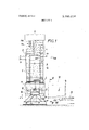
- FIG. 1 is a side view of the apparatus according to the present invention with the space in the vertical position and the lower platform in the down position;
- FIG. 2 is another side view of the apparatus with the lower platform advanced
- FIG. 3 is another side view showing the space in the horizontal position and the lower platform fully advanced
- FIG. 4 is a view taken in the diection of arrow IV of FIG. 3;
- FIG. 5 is a detail view of the tying mechanism used in the present invention.
- FIG. 6 is a detail view taken along line Vl-VI of FIG. 1.
- the present invention is employed with an apparatus 14 such as described in the above-mentioned commonly assigned patent application which produces a continuous helix 1 of steel wire.
- This apparatus 14 has guides 14a and 14b which maintain the helix 1 within inner and outer boundaries.
- the apparatus according to the present invention has four parallel inner guide rods 3 and four parallel outer guide rods 4 defining respective inner and outer cylinders 3a and 4a in turn delimiting a cylindrically annular space 20 which is vertical in FIGS. 1, 2, and 5, and horizontal in FIGS. 3 and 4. This space 20 when vertical is directly in line with the output of the supply apparatus 14.
- All of the guide bars 3 and 4 are secured on a common mounting plate 18 and slide in a pivotal guide 19. Cylinders 8 between the two elements 18 and 19 permit the guides 3 and 4 to be displaced through a distance
- the lower end of the space 20 is closed by a platform 2 which is formed by four plates 2a carried on a fourarmed web 2b secured to the end section of a threesection telescoping piston rod 7a-7c of a hydraulic cylinder 7 secured to the plate 19 of the apparatus.
- this lower platform 2 can be displaced from one end (FIG. 1) to the extreme other end (FIG. 3) of the space 20.
- the plate 19 is pivotal about a horizontal axis on a base 17 fixed to the plane floor.
- a large hydraulic cylinder 11 is connected to an arm 30 extending radially from the axis 10 and fixed to the housing 19 so as to rock the entire base 17 through 90, stops being provided so that the vertical and horizontal positions are maintained exactly.
- the top end of the space can be closed by a platform 5 formed by four disks 5a as shown in FIG. 6.
- Each disk 5a is oriented horizontally and is pivotal through 180 about a vertical pivot 5b by a motor 5c.
- the disk 5a is formed with a cutout 5c having a radius r of curvature equal to the radius of the outer cylinder 4a defined by the four angularly equispaced rods 4.
- the platform 5 formed by these disks 5a is in place, whereas in the position wherein these disks 5a have their cutouts 5c directed inwardly, the platform is in place.
- the platform blocking the upper end of the space 20 the helix of wire will form a pile 9 atop the platform 5, while in the other position the helix 1 will drop down in the space 20 onto the lower platform 2.
- a conveyor 13 is provided to one side of the apparatus, having two belts 13a driven continuously at a constant speed by a motor 13b.
- This conveyor is adapted to carry off packaged coils 12 of wire which are standing on their sides.
- the rods 3 and 4 are radially in line and each pair of facing rods is equipped with a tying mechanism 16 shown in detail in FIG. 5.
- This mechanism 16 comprises a supply 26 of highly ductile wire 24 which passes through a pair of rollers 29 driven by a motor 31.
- the end of the wire is first gripped in a solenoid-controlled clamp 21 carried on the free end of an arm pivotal about a horizontal axis on the rod 4.
- This arm 25 is then pivoted from the dot-dash position into the solid line position wherein it wedges the wire end into a spring clip 27 on a rotor 23 of a tieing device 28.
- the clamp 21 is then released to leave the end gripped in the upper clip 27 and the arm 25 is swung back into the dot-dash position.
- the rotor 23 is then rotated through l80.
- As wire fills up the space 20 a loop of wire is formed which runs from the clip 27 down the inside of the coil so formed, across the bottom under it, and up the outside over the pivot for the arm 25.
- the rollers 29 keep it under tension.
- the clamp 21 is again actuated to grip a median portion of the wire 24 and, after the platform 2 is lowered by the distance x, the arm 25 is again swung through 180 to engage another portion of the wire in the other spring clip.
- a cutter 22 is now actuated to clip the wire between the clip 27 and the clamp 21 and the arm 25 is rotated back into the dot-dash line position.
- the rotor 23 is then turned around several times to wind the two wire ends together, leaving the tie inside the coil.
- the wire will fill up the space 20 until the desired quantity for a package is present.
- the disks 50 will all be rotated through and a cutter 15 will be actuated to cut off this portion of wire.
- the platform 2 is raised to compact the coil against the underside of the platform 5.
- the platform 2 is then lowered by the distance x to allow the above-described tying operation to take place, and then the cylinders 8 are actuated to lower the guides 3 and 4 also by this distance x, the cylinder 11 is then actuated to tilt the entire assembly into the horizontal position, since with the guides 3 and 4 lowered they clear the bottom of the supply machine 14.
- One the horizontal position is attained the platform 2 is again advanced to push the tied-off package 12 off onto the conveyor 13.
- the various motors 5d, 13b, and 31 and cylinders 7, 8, and 11 are all centrally controlled to operate at a speed sufficient to keep ahead of the oncoming wire.
- the only variable part of the sequence of operations is the filling time for the space 20, which determines the size of the wire package to be made. All of the other operations can be made to take place at a predetermined maximum rate of speed so that this apparatus need only have one adjustment made when used with machines producing wire at different speeds, or when the input rate is changed for some reason.
- An apparatus for forming packaged coils of wire or the like supplied continuously in a helix comprising:
- said upper platform spaced from said lower platform in the direction of displacement thereof, said upper platform being displaceable between a first position terminating the other end of said space and receiving the continuously supplied wire and a second position allowing said wire to fall into said space onto said lower platform;
- said means for tying together said wire comprises means for passing a loop of an elongated tying element around said coil and means for winding together the ends of said loop.
- said means for tying together said wire further comprises means for radially passing an end of said tying element through said space and holding said end at the interior of said space, whereby descending turns of said helix fall on said element such that same forms a loop around it on the inside, bottom, and outside of said space, and means for inserting another portion of said element radially in through said space and connecting same to said means for winding together said ends of said loops.
Landscapes
- Engineering & Computer Science (AREA)
- Mechanical Engineering (AREA)
- Basic Packing Technique (AREA)
- Sheet Holders (AREA)
- Wire Processing (AREA)
- Coiling Of Filamentary Materials In General (AREA)
- Winding, Rewinding, Material Storage Devices (AREA)
Applications Claiming Priority (1)
| Application Number | Priority Date | Filing Date | Title |
|---|---|---|---|
| DE2152953A DE2152953A1 (de) | 1971-10-23 | 1971-10-23 | Vorrichtung zur bildung von insbesondere grossen drahtringen |
Publications (1)
| Publication Number | Publication Date |
|---|---|
| US3788210A true US3788210A (en) | 1974-01-29 |
Family
ID=5823242
Family Applications (1)
| Application Number | Title | Priority Date | Filing Date |
|---|---|---|---|
| US00300341A Expired - Lifetime US3788210A (en) | 1971-10-23 | 1972-10-24 | Apparatus for forming packaged coils of wire |
Country Status (8)
| Country | Link |
|---|---|
| US (1) | US3788210A (de) |
| JP (1) | JPS4850166A (de) |
| BE (1) | BE790439A (de) |
| DE (1) | DE2152953A1 (de) |
| FR (1) | FR2157616A5 (de) |
| IT (1) | IT969644B (de) |
| LU (1) | LU66338A1 (de) |
| NL (1) | NL7213996A (de) |
Cited By (6)
| Publication number | Priority date | Publication date | Assignee | Title |
|---|---|---|---|---|
| US4381704A (en) * | 1981-04-15 | 1983-05-03 | Inland Steel Company | Method and apparatus for removing irregular lap formations in coils of metal strip |
| WO2000066474A1 (en) * | 1999-05-03 | 2000-11-09 | Skaltek Ab | Methods and appratus to roll up a cable, wire, rope or the like in a ring |
| US6305277B1 (en) * | 1999-08-26 | 2001-10-23 | Illinois Tool Works Inc. | Coil handling device |
| US6701831B2 (en) | 2002-03-29 | 2004-03-09 | L & P Property Management Company | Apparatus and method for automated binding and spooling of wire cores |
| US6935665B2 (en) | 2002-03-29 | 2005-08-30 | L & P Property Management Co. | Apparatus and method for spooling of wire cores |
| CN106184869A (zh) * | 2015-04-29 | 2016-12-07 | 博尔富(江苏)实业有限公司 | 钢丝液压打捆机 |
Citations (2)
| Publication number | Priority date | Publication date | Assignee | Title |
|---|---|---|---|---|
| US3400652A (en) * | 1967-01-04 | 1968-09-10 | Morgan Construction Co | Coil bundle compress and tying mechanism |
| US3699880A (en) * | 1970-08-19 | 1972-10-24 | Kocks Gmbh Friedrich | Wire and rod handling apparatus |
-
0
- BE BE790439D patent/BE790439A/xx unknown
-
1971
- 1971-10-23 DE DE2152953A patent/DE2152953A1/de active Pending
-
1972
- 1972-10-16 NL NL7213996A patent/NL7213996A/xx unknown
- 1972-10-18 IT IT30602/72A patent/IT969644B/it active
- 1972-10-20 FR FR7237248A patent/FR2157616A5/fr not_active Expired
- 1972-10-20 LU LU66338A patent/LU66338A1/xx unknown
- 1972-10-23 JP JP47106111A patent/JPS4850166A/ja active Pending
- 1972-10-24 US US00300341A patent/US3788210A/en not_active Expired - Lifetime
Patent Citations (2)
| Publication number | Priority date | Publication date | Assignee | Title |
|---|---|---|---|---|
| US3400652A (en) * | 1967-01-04 | 1968-09-10 | Morgan Construction Co | Coil bundle compress and tying mechanism |
| US3699880A (en) * | 1970-08-19 | 1972-10-24 | Kocks Gmbh Friedrich | Wire and rod handling apparatus |
Cited By (7)
| Publication number | Priority date | Publication date | Assignee | Title |
|---|---|---|---|---|
| US4381704A (en) * | 1981-04-15 | 1983-05-03 | Inland Steel Company | Method and apparatus for removing irregular lap formations in coils of metal strip |
| WO2000066474A1 (en) * | 1999-05-03 | 2000-11-09 | Skaltek Ab | Methods and appratus to roll up a cable, wire, rope or the like in a ring |
| US6631864B1 (en) | 1999-05-03 | 2003-10-14 | Skaltek Ab | Method and apparatus to roll up a cable, wire, rope or the like in a ring |
| US6305277B1 (en) * | 1999-08-26 | 2001-10-23 | Illinois Tool Works Inc. | Coil handling device |
| US6701831B2 (en) | 2002-03-29 | 2004-03-09 | L & P Property Management Company | Apparatus and method for automated binding and spooling of wire cores |
| US6935665B2 (en) | 2002-03-29 | 2005-08-30 | L & P Property Management Co. | Apparatus and method for spooling of wire cores |
| CN106184869A (zh) * | 2015-04-29 | 2016-12-07 | 博尔富(江苏)实业有限公司 | 钢丝液压打捆机 |
Also Published As
| Publication number | Publication date |
|---|---|
| FR2157616A5 (de) | 1973-06-01 |
| NL7213996A (de) | 1973-04-25 |
| LU66338A1 (de) | 1973-01-23 |
| IT969644B (it) | 1974-04-10 |
| BE790439A (fr) | 1973-02-15 |
| JPS4850166A (de) | 1973-07-14 |
| DE2152953A1 (de) | 1973-04-26 |
Similar Documents
| Publication | Publication Date | Title |
|---|---|---|
| US3932982A (en) | Apparatus for placing folded boxes or the like in shipping cartons | |
| US3766706A (en) | Case packer | |
| US4060957A (en) | Method and apparatus for forming palletless packages | |
| US7736120B2 (en) | Palletizer puller bar | |
| US4593517A (en) | Method and apparatus for packing goods | |
| US2969629A (en) | Packing apparatus | |
| SU1279524A3 (ru) | Установка дл упаковки в пленку бесподдонного штабел мешков | |
| US3788210A (en) | Apparatus for forming packaged coils of wire | |
| US3509688A (en) | Processing cartons for packaging thereof | |
| CN109415174B (zh) | 用于包装产品的机器和方法 | |
| EP1053939A1 (de) | Vorrichting zum Herstellen von Netzverpackungen für gärtnerische Produkte in einem kontinuierlich abgewickelten Netzschlauch | |
| US3727370A (en) | Apparatus for loading containers | |
| EP0688731A1 (de) | Ausgabevorrichtung zum vereinzelten Verteilen von Blisterverpackungen, Streifen und dergleichen | |
| JPH04308152A (ja) | 照合用機器 | |
| US4693060A (en) | Apparatus for wrapping stacked goods | |
| US3400652A (en) | Coil bundle compress and tying mechanism | |
| SU946397A3 (ru) | Устройство дл укладки паковок крестовой намотки в контейнер | |
| US3572604A (en) | Conveyor device for coiling and tying wire | |
| US3727369A (en) | Fully automatic apparatus for loading containers with single pieces assembled in sheet-wrapped stacks, such as sacks or the like | |
| US3702524A (en) | Case loader with article inverting mechanism | |
| US4015732A (en) | Automatic palletizer method and apparatus | |
| US3581460A (en) | Wrapping machine | |
| CN207267559U (zh) | 包装机 | |
| US3241786A (en) | Wire packaging machine | |
| EP0561098A1 (de) | Automatische Vorrichtung zum Umwickeln einer palettisierten Ladung |
Legal Events
| Date | Code | Title | Description |
|---|---|---|---|
| AS | Assignment |
Owner name: MANNESMANN AKTIENGESELLSCHAFT, GERMANY Free format text: ASSIGNMENT OF ASSIGNORS INTEREST.;ASSIGNOR:FRIED. KRUPP GESELLSCHAFT MIT BESCHRANKTER HAFTUNG;REEL/FRAME:005238/0410 Effective date: 19891115 |