US3782664A - Automatic machine for forming rolls of piece-fabrics having a pre-established length and discarding of defective fabric - Google Patents
Automatic machine for forming rolls of piece-fabrics having a pre-established length and discarding of defective fabric Download PDFInfo
- Publication number
- US3782664A US3782664A US3782664DA US3782664A US 3782664 A US3782664 A US 3782664A US 3782664D A US3782664D A US 3782664DA US 3782664 A US3782664 A US 3782664A
- Authority
- US
- United States
- Prior art keywords
- fabric
- winding
- tube
- cutting
- machine according
- Prior art date
- Legal status (The legal status is an assumption and is not a legal conclusion. Google has not performed a legal analysis and makes no representation as to the accuracy of the status listed.)
- Expired - Lifetime
Links
- 239000004744 fabric Substances 0.000 title claims abstract description 163
- 230000002950 deficient Effects 0.000 title claims abstract description 31
- 238000004804 winding Methods 0.000 claims abstract description 80
- 238000005520 cutting process Methods 0.000 claims abstract description 66
- 238000003825 pressing Methods 0.000 claims description 16
- 238000007599 discharging Methods 0.000 claims description 4
- 230000005484 gravity Effects 0.000 claims description 4
- 238000005259 measurement Methods 0.000 claims description 3
- 238000005096 rolling process Methods 0.000 claims description 3
- 238000003860 storage Methods 0.000 claims description 2
- 239000000123 paper Substances 0.000 abstract description 20
- 239000011111 cardboard Substances 0.000 abstract description 15
- 230000015572 biosynthetic process Effects 0.000 abstract description 3
- 230000007547 defect Effects 0.000 description 4
- 230000000694 effects Effects 0.000 description 3
- 230000011664 signaling Effects 0.000 description 3
- 230000000903 blocking effect Effects 0.000 description 2
- 238000004519 manufacturing process Methods 0.000 description 2
- 238000000034 method Methods 0.000 description 2
- 238000007792 addition Methods 0.000 description 1
- 238000010276 construction Methods 0.000 description 1
- 238000005304 joining Methods 0.000 description 1
- 239000000463 material Substances 0.000 description 1
- 239000002184 metal Substances 0.000 description 1
- 238000012986 modification Methods 0.000 description 1
- 230000004048 modification Effects 0.000 description 1
- 230000000284 resting effect Effects 0.000 description 1
- 230000000717 retained effect Effects 0.000 description 1
- 238000009958 sewing Methods 0.000 description 1
- 239000002699 waste material Substances 0.000 description 1
Images


Classifications
-
- D—TEXTILES; PAPER
- D06—TREATMENT OF TEXTILES OR THE LIKE; LAUNDERING; FLEXIBLE MATERIALS NOT OTHERWISE PROVIDED FOR
- D06H—MARKING, INSPECTING, SEAMING OR SEVERING TEXTILE MATERIALS
- D06H7/00—Apparatus or processes for cutting, or otherwise severing, specially adapted for the cutting, or otherwise severing, of textile materials
- D06H7/02—Apparatus or processes for cutting, or otherwise severing, specially adapted for the cutting, or otherwise severing, of textile materials transversely
-
- B—PERFORMING OPERATIONS; TRANSPORTING
- B65—CONVEYING; PACKING; STORING; HANDLING THIN OR FILAMENTARY MATERIAL
- B65H—HANDLING THIN OR FILAMENTARY MATERIAL, e.g. SHEETS, WEBS, CABLES
- B65H19/00—Changing the web roll
- B65H19/22—Changing the web roll in winding mechanisms or in connection with winding operations
- B65H19/2207—Changing the web roll in winding mechanisms or in connection with winding operations the web roll being driven by a winding mechanism of the centre or core drive type
-
- D—TEXTILES; PAPER
- D06—TREATMENT OF TEXTILES OR THE LIKE; LAUNDERING; FLEXIBLE MATERIALS NOT OTHERWISE PROVIDED FOR
- D06H—MARKING, INSPECTING, SEAMING OR SEVERING TEXTILE MATERIALS
- D06H3/00—Inspecting textile materials
-
- B—PERFORMING OPERATIONS; TRANSPORTING
- B65—CONVEYING; PACKING; STORING; HANDLING THIN OR FILAMENTARY MATERIAL
- B65H—HANDLING THIN OR FILAMENTARY MATERIAL, e.g. SHEETS, WEBS, CABLES
- B65H2301/00—Handling processes for sheets or webs
- B65H2301/40—Type of handling process
- B65H2301/41—Winding, unwinding
- B65H2301/417—Handling or changing web rolls
- B65H2301/418—Changing web roll
- B65H2301/4181—Core or mandrel supply
- B65H2301/41814—Core or mandrel supply by container storing cores and feeding through wedge-shaped slot or elongated channel
-
- B—PERFORMING OPERATIONS; TRANSPORTING
- B65—CONVEYING; PACKING; STORING; HANDLING THIN OR FILAMENTARY MATERIAL
- B65H—HANDLING THIN OR FILAMENTARY MATERIAL, e.g. SHEETS, WEBS, CABLES
- B65H2301/00—Handling processes for sheets or webs
- B65H2301/40—Type of handling process
- B65H2301/41—Winding, unwinding
- B65H2301/417—Handling or changing web rolls
- B65H2301/418—Changing web roll
- B65H2301/4182—Core or mandrel insertion, e.g. means for loading core or mandrel in winding position
- B65H2301/41826—Core or mandrel insertion, e.g. means for loading core or mandrel in winding position by gripping or pushing means, mechanical or suction gripper
-
- D—TEXTILES; PAPER
- D05—SEWING; EMBROIDERING; TUFTING
- D05D—INDEXING SCHEME ASSOCIATED WITH SUBCLASSES D05B AND D05C, RELATING TO SEWING, EMBROIDERING AND TUFTING
- D05D2305/00—Operations on the work before or after sewing
- D05D2305/50—Removing cut-out material or waste
-
- Y—GENERAL TAGGING OF NEW TECHNOLOGICAL DEVELOPMENTS; GENERAL TAGGING OF CROSS-SECTIONAL TECHNOLOGIES SPANNING OVER SEVERAL SECTIONS OF THE IPC; TECHNICAL SUBJECTS COVERED BY FORMER USPC CROSS-REFERENCE ART COLLECTIONS [XRACs] AND DIGESTS
- Y10—TECHNICAL SUBJECTS COVERED BY FORMER USPC
- Y10T—TECHNICAL SUBJECTS COVERED BY FORMER US CLASSIFICATION
- Y10T83/00—Cutting
- Y10T83/525—Operation controlled by detector means responsive to work
- Y10T83/541—Actuation of tool controlled in response to work-sensing means
- Y10T83/543—Sensing means responsive to work indicium or irregularity
Definitions
- ABSTRACT A machine for the automatic formation of rolls of piece-fabrics having a pre-estab1ished length is pro vided with a winding up device, a plane on which the fabric is fed, a cutting device actuated by sensor means responsive to signals applied to the fabric or to a counting device, gripper means adapted to seize therebetween the fabric after the cutting operation and carry it to the winding up device, a feeder of card board tubes which are the core of the rolls, said feeder comprising means adapted to unwind a sheet of paper from each tube and means for positioning thereafter the tube on the winding up device so that the end of fabric drawn by said gripper means, held between the tube and the unwound sheet of paper, is the origin of a new roll of fabric.
- An automatiic device for discarding the defective fabric is also provided, when the beginning and the end of each defective length of fabric is indicated by previously applied signals.
- the above mentioned cutting device carries out two cutting operations and the two fabric edges are then joined together by overlapping and the winding up of the roll continued.
- a device for counting the length of defective fabric is also preferably provided.
- Said operation is carried out manually, i.e., a worker, after having established in any known manner that the length is the desired one, causes the machine to stop, cuts the fabric, removes the small roll formed, puts into the machine a new cardboard tube which constitutes the core of the roll whereonto he causes to be wound up another 50 m long piece ready for sale.
- This sequence of operations obviously involves a considerable waste of time and labour, so that the advantages obtained by effecting the finishing operations on very long pieces of fabrics are considerably reduced.
- the machine according to this invention essentially comprises a pair of grippers which are adapted to stop the fabric in the points where the piece has to be cut and, subsequently, to feed the fabric again; a cutting device for cutting the fabric in order to separate one piece from the other; a feeder of tubes on which the roll has to be formed; an automatic winding up device; and means for discarding the defective fabric.
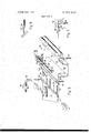
- FIG. 1 shows a schematic perspective view of a first embodiment of the machine according to this invention
- FIG. 2 shows a second embodiment of the machine according to this invention
- FIG. 3 shows a detail of FIG. 1 or FIG. 2;
- FIG. 4 shows a schematic side-view of the machine according to FIG. 1 without the tube feeder and illustrating in particular the automatic winding up group;
- FIG. 5 shows an end-view taken from the righthand side of FIG. 4
- FIG. 6 represents a perspective view of the same machine in particular with reference to the automatic discarding device of the defective fabric
- FIG. 7 represents a schematic side-view of a detail of FIG. 6 during a given operating moment.
- FIG. 8 represents an enlarged perspective view of a detail of the machine as represented in FIG. 6.
- the fabric 1 coming from the finishing machine and moving forward from the left-hand to the right-hand side along the direction of the arrow F.
- the fabric in question consists of a plurality of big pieces joined together to expedite the finishing operation.
- signaling means 6 which are normally self-sticking phosphorescent pieces of paper existing in trade and capable of exciting a photoelectric cell 7.
- said signaling means 6 might also be different, such as e.g. magnetized or in general metal signals, i.e., elements which can be sensed by an electric, electronic or pneumatic sensing element 7..
- the signaling plates 6 or the equivalent elements are placed every 500 m, i.e. at the point where the big pieces are joined together. Consequently, if only this signal should exist, the winding up machine would stop only every 500 m. Since on the contrary a cutting has to be performed every 50 m, another already known measuring apparatus, e.g., a
- the fabric 1 when advancing from the left-hand side to the right-hand side in the sense of arrow F, the fabric 1 passes through a pair of open grippers 3 and 3, then over a plane 4 provided with two parallel slots 5 and 5' perpendicular to the advancement sense of the fabric, above which the sensing device 7 is arranged.
- the cutting disks 8 and 8 can run in these slots, as they are caused to rotate by the motor 9 and driven along the width of the fabric on the supports 10 and 10 by a pneumatic or electric driving means, not shown in the figure. This constitutes the fabric cutting device.
- the feeder of empty cardboard tubes constituting the core of the rolls to be formed includes a magazine of empty tubes 12 with an underlying feeding carriage 13 actuated by a pneumatic piston 14 and provided with a feeding slot 17.
- a tube 16 coming from the container 12 falls into the slot 17.
- the piston 14, moving towards the lefthand side brings the carriage to the position represented by a full line in FIG. 1, i.e., with the tube 14 in the position 16' inside the slot situated in 17.
- a device for picking up the tubes consisting of a pneumatic piston 21 which bears centrally through a support 22 a bar 21a, along which two lever arms 18 and 18' can slide through two supports 22' and 22" under the action of two pistons 19 and 19'.
- the lower end of each lever arms 18, 18' bears a conical mandrel 20 and 20' respectively.
- the two pistons 19 and 19' cause the two lever arms 18 and 18' to close, so that the conical mandrels 20 and 20' are introduced into the two ends of the tube, while catching it strongly.
- the piston 21 will come down, thus bringing the tube 16 into the position 16".
- the pistons 19 and 19' will cause the two arms 18 and 18' to be removed, thus causing the mandrels to be disengaged from the ends of the tube which will fall into the tray 23 to be then seized again by the conical mandrel 24 of the winding up device. Thereafter, the tray 23 will come down in order not to interfere with the winding operation.
- the mandrel indeed, not only has a translatory movement in the longitudinal sense of the tube, as indicated by the arrow H, but also has a rotatory movement in the sense of the arrow G imparted eg by a pulley connected to a motor, since besides having to hold the tube, it will also have to effect the winding operation in order to form the desired roll.
- FIG. 3 better shows the grippers 3 and 3' opened, while the fabric 1 indicated by a dashed line passes between them.
- the cutting disks 8 and 8' which, keyed on the shaft 27, enter the slots 5 and 5 respectively, and rotating whirlingly cut the fabric.
- These cutting disks as indicated in FIG. 1, after having entered the working plane 4 to cut the fabric come out completely therefrom and are positioned outside of the path of the fabric.
- FIG. 4 shows the grippers 3 and 3 closed which have pressed between them the fabric 1 as a result of the action of piston 25 which has pushed downwards the gripper 3.
- the control impulse to piston 25 is given by the sensing device 7 or by the above-said means for measuring the length of the roll to be formed.
- the part of plane 4 bearing such slots and which is pivotedly mounted on the fulcrum 26 rotates, under the action of a not represented pneumatic piston, in order not to hamper the following operations, and is positioned as indicated by the dashed line in FIG. 4.
- the pneumatic piston 30 operates the supporting carriage 28 of the pair of grippers 3 and 3 and by causing it to slide along the guiding rail 29, brings it into the position indicated by 28 drawing with it the grippers 3 and 3' which still press between them the fabric 1.
- the piece of fabric pressed by the grippers 3 and 3' will have to constitute the beginning of a new roll, the preceding roll being completed and separated by the cutting of the fabric. Once formed, the roll will have to be removed from the winding device, to permit the mandrel 24 to clasp a new tube 16" onto which the piece of fabric carried by the pair of grippers will have to be wound up.
- the feeding carriage which is driven by the piston 14 conveys the tube 16 into the position 16', then, the conical mandrels 20 and 20 close under the action of the pistons 19 and 19, they clasp the tube and lift it while the carriage 13 returns to its backward position whereafter they lower it to the position 16", asexplained before.
- a motor 35 through the pulleys 41 and 42, causes the mandrels 20 and 20', and consequently the cardboard tube held by them, to rotate in the opposite sense with respect to the normal winding up sense.
- a plurality of nozzles 36, 36', 36" etc. direct a blow of compressed air tangentially onto the tube 16". Since on these tubes, already known in trade, there is commonly wound up a certain quantity of paper, the combined action with a contrary effect of the rotation imparted by the motor 35 and the air jets of the nozzles 36, causes the paper to be unwound.
- the piece of paper which is unwound from the tube 16" falls down until it is sensed by the photoelectric cells 37 and 37' which send to the motor 35 an impulse causing it to stop.
- a timer 38 which starts to count the time upon the entering into action of the motor 35. If, after a certain pre-established time length, the photoelectric cells 37 and 37 have not sensed the presence of the lower edge of the paper 39, this means that there is some defect which has prevented the paper from being unwound,'so that the timer 38 causes the stopping of the machine on which the intervention of an operator is required, the operator being called, if so devised, by an auxiliary acoustic or luminous alarm signal.
- This type of safety device is very important in the operation of the machine of this invention.
- the piston 21 immediately drives again upwards the bar 21a with the supports 22, 22' and 22" and thus also the arms 18 and 18' which are lifted leaving clear room for the following operations.
- the mandrel 24 actuated by the piston 43 moves from the left-hand to the righthand side and holds the cardboard roll 16" which in the meantime rested free on the tray 23.
- the tray 23 will preferably have a concave, in particular semicylindrical shape, to avoid that the tube 16" can roll away.
- the grippers 3 and 3' pushed by the piston 30, had arrived into the position 28' of their supporting carriage, still keeping tightly between them the piece of fabric with which a new roll will have to begin.
- the lower gripper 3 is provided with a cam in the form of a sloping plane 44 contrasting in the position 28' a fixed projection 45 having an opposite slope which causes the pair of grippers to stop and rotate. In this position, the fabric 1 is in contact with the roll 16" while the paper 39' unwound from the roll passes over the cylinder 47 which is integral with the tray 23.
- the piston 46 causes the lowering of the edge of the tray situated in front of that on which the cylinder 47 is mounted and, since the tray 23 has its fulcrum in the central point 48, the cylinder 47 is lifted and presses the cardboard roll 16', so that the fabric 1 is compressed between the cardboard roll and the paper 39.
- the grippers 3 and 3' open themselves and return to their initial position.
- the motor 49 (FIG. 5) through the pulleys 50 and 51 causes the mandrel 24 to rotate, so that the cardboard tube 16" starts to rotate driving with it the fabric and the piece of paper and starts to form a new roll.
- the piston 52 causes the lowering of the support 53 of the tray 23 to avoid that the roll which is being formed would collide against the latter owing to its growing diameter.
- the plane 4 again rotates of upwards and takes again its initial position in front of the grippers 3 and 3 to make possible a further cutting operation of the fabric.
- FIG. 2 a second embodiment of the machine is represented as in FIG. 1, wherein the grippers 3 for carrying the initial piece of fabric of each new roll are caused to move by a lever 28" instead of the carriage 28 thus simplifying the rotation of the pair of grippers at the end of their travel towards the winding up device.
- the actual winding up device is slightly modified since 24 does not indicate a mandrel provided also with a translatory movement and adapted to hold the cardboard roll for the winding up operation, but simply is the shaft of a roll X on which there rests frictionally driven, the cardboard tube supported by the mandrel 20.
- the automatic winding up machine has been represented taking particularly into account the device for discarding automatically the pieces of defective fabric.
- signals indicating the beginning and the end of each defective piece.
- Said sig nals can be sensed by appropriate sensing elements and are e.g., either phosphorescent papers capable of exciting a photoelectric cell situated in a fixed position or magnetic, metallic, etc., elements, which can be detected by any known means, so that, when the defective fabric arrives on or a little before the slot 5 of the advancement plane along which the fabric is cut, the signal detecting element (not shown in the figure) sends an impulse to the fabric feedirig device, causing it to stop and blocking the fabric 1 in this position for the cutting operation.
- the blade 8 of the cutting device rolling over the slot 5 cuts the fabric, of which the portion pertaining to the piece being wound up falls down by gravity onto a roll 64 parallel to the cylinders X and 47 of the winding up device and situated in an intermediate position between these and the cutting device.
- a series of suction members 62 connected through a flexible pipe 61 to a vacuum source 60. Said members 62 can slide over the fabric 1 through pairs of small rollers 67, under the action of a double-effect cylinder 63. Moreover, there is provided a pair of rollers 54 positioned transversely and on opposite parts with respect to the fabric so as to press it while effecting, if operated, a conveying action on thefabric.
- a specific friction device blocks the winding up device, causing the stopping of the shaft 24 of the roll X, and consequently of the fabric already wound up on the tube 16, the cut-off portion of which, retained by the roll 64, falls vertically along a certain length.
- the rollers 54 are operated and cause the defective fabric comprised between them to move forward, feeding it to the underlying container 68 (from the lefthand to the right-hand side in the drawing).
- means suited to push the fabric downwards, into the container 68 can consist e.g., of jets of compressed air emitted by a number of nozzles 56 arranged along a conveying pipe 55, but could be made in any other known manner.
- the end of defective piece will be detected by the presence of a signal of the fabric passing in front of an element which is sensing to said signal. A new impulse will therefore be given for stopping the fabric 1 and for operating the cutting device.
- the cylinder 63 will actuate the advancing of the suction members 62, which, once they are in the position 5, will cause the fabric 1 to move forward, drawing it with them owing to the suction force applied.
- the suction members 62 after having overcome the zone corresponding to the container 68, will bring the fabric into the position indicated in FIG. 7, i.e. with the end Y beyond the roll 64 on which the pairs of small rollers 67 are resting at the end of the travel of the series of suction numbers 62.
- the suction in the members 62 stops, since they are disconnected from vacuum source 60.
- connection may e.g., be assured by a normally closed valve having a push-button 65 for controlling the opening thereof, as indicated in FIG. 2, is operated only over a certain portion of the advancement travel of the suction group, e.g., by a contrast element 66 having a pre-established length.
- the two ends of fabric are kept together by the reciprocal friction action effected during the winding up of the total length of the overlapping portion, corresponding to the distance between the roll 64 and the point Y to which it is to be added the length of the extreme piece which hangs vertically by gravity into the container 68. It should be noticed moreoever that the position Y wherein the front end of the fabric is left, drawn by the suction members 62, is rather close to the roll already wound up onto the cylinder 16, so that the winding up tension on the piece is soon added to the above said friction strength between the two layers of fabric.
- the piston 63 controls the return of the members 62 (without suction) in the starting position represented in FIG. 6.
- An appropriate measuring device e.g., a counting device C driven by advancement of fabric 1 and rendered operative upon sensing of the signal detecting element, had meanwhile measured the length of the discarded piece of defective fabric, which measurement is in any known manner memorized and will be taken into account by counting device C for recording the length of the fabric and for determining the cutting of the piece at each preestablished length.
- auxiliary devices may be changed.
- a different method may be used to bring the piece of fabric next to the winding roll without the rotation of the pressing grippers but for example by lowering first the pressure which is integral with the supporting tray of the roll and lifting it thereafter as said precedingly.
- the controlling cylinders may not only pneumatic, but also hydraulic or oleodynamic or, if so desired, replaced by electromagnetic controlling devices. There will be provided moreover all connections, relays, limit switches, electrovalves for controlling the cylinder position systems, timers, etc., required to ensure coordination and synchronization of the various operating stages.
- An automatic machine for forming rolls of piecefabrics having a pre-established length around tubes provided with sheets of paper wound thereon which comprises means for pressing the fabric therebetween along the width thereof and for feeding it to a winding up device; means for cutting the fabric transversely; means for feeding the tubes, which are the cores of the rolls to be formed, and adapted to bring each tube first in an intermediate position and subsequently in a winding up position; means for causing each tube to rotate in said intermediate position in a sense opposite to the winding up sense and cooperating with pneumatic means sending tangential jets of compressed air onto said tube in order to partially unwind therefrom the sheet of paper wound up precedingly; and means for winding up the fabric onto said tube and for discharging the complete roll; actuating means being provided for controlling said pressing means and said cutting means, which are responsive to signals applied on the fabric and to a counting device for measuring the length of the fabric.
- said means for pressing and feeding the fabric consists of a pair of gripper elements extending over the entire width of the fabric and adapted to be brought close to each other while pressing the fabric between them, and to move forward to the winding up position, while drawing the grasped piece of fabric.
- one of said gripper elements is integral with a carriage sliding in a guide parallel to the path of the fabric, under the action of a reciprocating cylinder and the other gripper element is movable with respect to said first gripper element under the action of a cylinder-piston system.
- said gripper element which is integral with said carriage has a cam adapted to contact a corresponding fixed projection close to the winding up position, which stops the travel of said pair of grippers and causes the pair of grippers to rotate until their front part is introduced between the tube in the winding up position and an auxiliary tightening means provided on said winding up means.
- one of said gripper elements is integral with a lever sliding parallel to the path of the fabric and rotatably mounted around an axis which is parallel to the length of said gripper elements and perpendicular to said path and the other gripper element is slidably mounted on said lever for a reciprocating movement to and from said one gripper element, said gripper element which is integral with said lever having a cam adapted to contact a corresponding fixed projection close to the winding up position, whereby said pair of grippers are rotated in a position close to the winding up position, until their front part is introduced between the tube in the winding up position and an auxiliary tightening means provided on said winding up means.
- said cutting means consists at least of one rotating blade mounted onto a carriage provided with a reciprocating transversal movement with respect to the fabric and adapted to move within corresponding pairs of grooves provided on a tiltable cutting plane which is co-planar with the surface determined by said two gripper elements in their pressing position.
- said means for feeding the tubes comprises a magazine for the storage of empty tubes, an underlying charging carriage actuated by a cylinder for feeding one tube at each actuation of said carriage to a position where the tube is grasped by hooking elements for being brought into said intermediate position.
- said hooking elements comprise two parallel arms having at one end a conical mandrel, said arms being slidably mounted at the other end for movement along a bar under the action of two driving cylinders, said bar being connected to a third cylinder for movement perpendicular with respect to that of the above two arms on the bar.
- said means in said intermediate position causes the rotation of the mandrels of said hooking means and comprises a device adapted to sense that said sheet of paper unwound from the tube and fallen by gravity has reached a certain position, causing contemporarily the rotation of the tube to stop and the lowering of said means for hooking the tube to continue.
- said winding up means comprises a pair of lever arms provided with conical mandrels one of which at least has a longitudinal translatory movement for introducing itself into the tube in the winding up position and a rotatory movement given by a motor mounted on one of said arms for winding up the fabric, between said pair of arms there being mounted means adapted to support the tube before it is grasped by said pair of mandrels and after it has been left by said hooking means, said pair of arms being inclinable under the action of a driving cylinder until they stand over a container of complete rolls.
- said supporting means of the tube comprises an elongated element having a concave supporting surface adapted to receive said tube when it is released by the above said hooking means and provided with a vertical translatory movement under the action of two cylinders integral with said pair of lever arms, which cause said supporting element to be lowered when the tube is grasped by said pair of mandrels of the above said winding up means, and an auxiliary tightening means integral with said elongated element.
- said winding up means comprises a pair of lever arms having mounted therebetween a roll, and actuating means for the rotation of said roll which is capable of frictionally driving said tube to be wound up.
- a machine for forming rolls of piece-fabrics around tubes provided with sheets of paper wound thereon comprising: means for pressing the fabric therebetween along the width thereof and for feeding it to a winding up device; means for cutting the fabric transversely; means for feeding the tubes, which are the cores of the rolls to be formed, and adapted to bring each tube first in an intermediate position and subsequently in a winding up position; means for causing each tube to rotate in said intermediate position in a sense opposite to the winding up sense and cooperating with pneumatic means sending tangential jets of compressed air onto said tube in order to partially unwind therefrom the sheet of paper wound up precedingly; and means for winding up the fabric onto said tube and for discharging the complete roll; actuating means being provided for controlling said pressing means and said cutting means, which are responsive to signals applied on the fabric and to a counting device for measuring the length of the fabric; means responsive to signals provided on the fabric at the beginning and at the end of each portion of defective fabric, for controlling the stopping of said winding up means and the operation of
- a machine according to claim 14 further comprising a roll element parallel to the shaft of the winding up roll and situated preceding the latter in the fabric feeding forward sense and at the level of the advancement plane of the fabric, said roll element being adapted to retain around it, during the falling into said container, the end of the already wound up fabric after said first cutting operation.
- said suction means comprises a plurality of parallel apertured members provided each with a pair of lateral rollers for rolling over the fabric and connected through a valve, controlled by external operating means, to a suction source, means being provided for moving said plurality of suction members to a position where said pairs of rollers are caused to correspond with said roll element thus overlapping therebetween the two portions of fabric separated by the two cutting operations, and for bringing said suction members back to the initial position.
Landscapes
- Engineering & Computer Science (AREA)
- Textile Engineering (AREA)
- Chemical & Material Sciences (AREA)
- Materials Engineering (AREA)
- Replacement Of Web Rolls (AREA)
Applications Claiming Priority (2)
| Application Number | Priority Date | Filing Date | Title |
|---|---|---|---|
| IT2113871 | 1971-02-27 | ||
| IT2036872A IT1003034B (it) | 1972-02-09 | 1972-02-09 | Macchina perfezionata per formare potoli di tessuti in pezza di lun ghezza prefissata con scarto auto matico del tessuto difettoso |
Publications (1)
| Publication Number | Publication Date |
|---|---|
| US3782664A true US3782664A (en) | 1974-01-01 |
Family
ID=26327509
Family Applications (1)
| Application Number | Title | Priority Date | Filing Date |
|---|---|---|---|
| US3782664D Expired - Lifetime US3782664A (en) | 1971-02-27 | 1972-02-25 | Automatic machine for forming rolls of piece-fabrics having a pre-established length and discarding of defective fabric |
Country Status (7)
| Country | Link |
|---|---|
| US (1) | US3782664A (enExample) |
| BE (1) | BE779853A (enExample) |
| CH (1) | CH531984A (enExample) |
| DE (1) | DE2209435C3 (enExample) |
| ES (1) | ES400106A1 (enExample) |
| FR (1) | FR2127953A5 (enExample) |
| GB (1) | GB1375903A (enExample) |
Cited By (32)
| Publication number | Priority date | Publication date | Assignee | Title |
|---|---|---|---|---|
| US4116398A (en) * | 1977-04-07 | 1978-09-26 | Central States Tooling Service, Inc. | Automatic ribbon winding machine |
| US4277032A (en) * | 1978-11-29 | 1981-07-07 | Pietro Alberto | Automatic apparatus for continuously forming cloth rolls |
| DE3018269A1 (de) * | 1980-05-13 | 1981-11-19 | B. Hagemann & Co, 4430 Steinfurt | Verfahren zum starten des wickelvorganges bei einer wickelvorrichtung und wickelvorrichtung zur durchfuehrung des verfahrens |
| US4329896A (en) * | 1980-04-09 | 1982-05-18 | Karl Singer | Slitter for severing laminated objects |
| US4721263A (en) * | 1985-01-28 | 1988-01-26 | Japan Tobacco, Inc. | Device for automatically stripping and delivering fore end of a paper roll |
| US4930711A (en) * | 1989-01-17 | 1990-06-05 | Krantz America, Inc. | Automatic defect cutting assembly for a continuous fabric winder |
| US4934620A (en) * | 1988-01-18 | 1990-06-19 | Guido Rossi | Apparatus for winding coaxial insulation onto a winding core |
| US5040737A (en) * | 1989-03-15 | 1991-08-20 | Agfa-Gevaert Ag | Cutting and winding device for film strips |
| US5374006A (en) * | 1992-03-04 | 1994-12-20 | Ciba-Geigy Corporation | Method and apparatus for winding substrates that are capable of being wound |
| US5419511A (en) * | 1992-08-26 | 1995-05-30 | Yoshida Kogyo K.K. | Automatic winding machine for tape-like articles |
| US5540166A (en) * | 1994-03-16 | 1996-07-30 | Diversified Systems, Inc. | Edge steer finishing device and method |
| US5810279A (en) * | 1997-06-04 | 1998-09-22 | Sandar Industries, Inc. | System and method for severing and spooling a web |
| EP1215153A3 (de) * | 2000-12-18 | 2003-04-02 | Unicor Extrusionstechnik GmbH | Anlage zum automatischen optimierten Aufwickeln von Schlauchstücken |
| DE10162179A1 (de) * | 2001-12-18 | 2003-07-10 | G & L Heikaus Kunststoffverarb | Bereitstellungsvorrichtung für Folienrollenkerne und Verfahren zum Bereitstellen von Folienrollenkernen |
| US6629662B2 (en) * | 2001-06-20 | 2003-10-07 | Tuftco Finishing Systems, Inc. | Method and apparatus for rolling carpet |
| US20090049990A1 (en) * | 2007-08-23 | 2009-02-26 | William Christopher Schutte | Steamer insert apparatus |
| US20100136194A1 (en) * | 2007-10-24 | 2010-06-03 | William Christopher Schutte | Steamer insert apparatus |
| CN101280511B (zh) * | 2007-04-04 | 2010-11-03 | 鲁泰纺织股份有限公司 | 自动对边卷布量布机 |
| US20110180651A1 (en) * | 2010-01-27 | 2011-07-28 | Production Design, Inc. | Adjustable bed mat roller |
| CN102950609A (zh) * | 2012-10-29 | 2013-03-06 | 宁波方力科技股份有限公司 | 一种用于塑料管的切割机 |
| CN102950606A (zh) * | 2012-12-10 | 2013-03-06 | 常州台源电测材料科技有限公司 | 纸管切管装置 |
| US8960587B2 (en) | 2011-05-27 | 2015-02-24 | Umana Family Corporation | Rear discharge mat rolling machine |
| CN104418136A (zh) * | 2013-08-22 | 2015-03-18 | 富士胶片株式会社 | 网切断方法及网切断装置 |
| CN104805673A (zh) * | 2015-05-15 | 2015-07-29 | 青岛金江源工业装备有限公司 | 一种具有切断和缠绕功能的尼龙质量检测装置 |
| CN105253672A (zh) * | 2015-10-15 | 2016-01-20 | 江苏润云纺织科技有限公司 | 一种断布机拉布装置 |
| CN107381170A (zh) * | 2017-06-23 | 2017-11-24 | 上海融经互联网科技发展有限公司 | 布草通道机 |
| CN107398945A (zh) * | 2017-08-31 | 2017-11-28 | 浙江美诺地毯制造有限公司 | 一种新型地毯切割装置 |
| US9884694B2 (en) | 2012-09-19 | 2018-02-06 | Mat Processing, Llc | Rear discharge mat rolling machine with wrapper |
| CN110587720A (zh) * | 2019-10-15 | 2019-12-20 | 靖江国林木业有限公司 | 一种原木分选线用定长裁切装置 |
| CN114045656A (zh) * | 2021-11-11 | 2022-02-15 | 重庆奥轩服饰有限公司 | 一种服装生产剪裁方法及系统 |
| CN114803626A (zh) * | 2022-06-06 | 2022-07-29 | 江苏新丝路纺织科技有限公司 | 一种用于高弹丝面料的裁切装置及其裁切方法 |
| CN117003036A (zh) * | 2023-09-28 | 2023-11-07 | 云南欣城防水科技有限公司 | 一种石墨烯防水卷材预处理夹具 |
Families Citing this family (14)
| Publication number | Priority date | Publication date | Assignee | Title |
|---|---|---|---|---|
| US4201620A (en) * | 1978-11-29 | 1980-05-06 | Phillips Petroleum Company | Web rolling apparatus |
| DE3024389C2 (de) * | 1980-06-28 | 1985-09-26 | Carl Schmale GmbH & Co KG, 4434 Ochtrup | Querschneidevorrichtung für Textilbahnen |
| SE452497B (sv) * | 1984-11-02 | 1987-11-30 | Akerlund & Rausing Ab | Forfarande och anordning for applicering av ett yttre holje pa en rorformig kropp av isolermaterial |
| JPH04371441A (ja) * | 1991-06-18 | 1992-12-24 | Bridgestone Corp | 帯状部材の巻取装置 |
| DE4429281A1 (de) * | 1994-08-19 | 1995-03-23 | Losberger Sonnenschutz | Verfahren und Vorrichtung zum Konfektionieren großflächiger flexibler Flächengebilde |
| FR2751952B1 (fr) * | 1996-07-30 | 1998-08-28 | Ictb Macotex | Installation permettant de reconditionner sous la forme d'un enroulement une matiere en bande, telle qu'une etoffe |
| CN106758105B (zh) * | 2016-12-30 | 2023-07-25 | 广东瑞洲科技有限公司 | 一种工作效率高的切割机头 |
| CN109665385B (zh) * | 2018-12-21 | 2020-05-12 | 威海市龙升精密机械股份有限公司 | 一种ro膜自动卷膜机及一种ro膜的制备方法 |
| CN110055739A (zh) * | 2019-05-20 | 2019-07-26 | 天津市立颖地毯制造有限公司 | 一种绒织地毯切割机 |
| CN111705537B (zh) * | 2020-06-23 | 2022-03-22 | 武汉利发诚品纸业有限公司 | 全自动纤维卫生纸生产线及生产方法 |
| CN112960440B (zh) * | 2021-04-20 | 2025-03-25 | 东莞市泓强机械有限公司 | 薄膜自动分切复卷机 |
| CN113942868B (zh) * | 2021-12-20 | 2022-03-04 | 沛县嘉创电子科技有限公司 | 一种纺织材料自动切断收纳装置及方法 |
| CN114803621B (zh) * | 2022-06-29 | 2022-09-06 | 张家港市棋瑞德机械制造有限公司 | 一种光伏焊带设备用防掉线装置 |
| CN116281339B (zh) * | 2023-02-07 | 2023-10-03 | 扬州阿特兰新材料有限公司 | 一种无纺布生产用切边废料收卷设备 |
Citations (4)
| Publication number | Priority date | Publication date | Assignee | Title |
|---|---|---|---|---|
| US2006499A (en) * | 1933-05-22 | 1935-07-02 | Paper Patents Co | Paper metering, cutting, and reeling |
| US2999653A (en) * | 1957-04-11 | 1961-09-12 | Johnson & Johnson | Machine for winding log roll |
| US3122956A (en) * | 1964-03-03 | Apparatus for detecting and removing defective | ||
| US3592403A (en) * | 1968-04-08 | 1971-07-13 | Weser Lenze Stahlkontor | Apparatus for replacing cores and severing webs in high-speed multiple winding machines |
Family Cites Families (4)
| Publication number | Priority date | Publication date | Assignee | Title |
|---|---|---|---|---|
| DE200101C (enExample) * | ||||
| US2312626A (en) * | 1940-07-12 | 1943-03-02 | Bethlehem Steel Corp | Strip marking device |
| US2503051A (en) * | 1946-04-09 | 1950-04-04 | Joseph F Jeckert | Material cutting and measuring device |
| BE557403A (enExample) * | 1955-07-02 |
-
1972
- 1972-02-24 ES ES400106A patent/ES400106A1/es not_active Expired
- 1972-02-25 CH CH268272A patent/CH531984A/it not_active IP Right Cessation
- 1972-02-25 BE BE779853A patent/BE779853A/xx not_active IP Right Cessation
- 1972-02-25 US US3782664D patent/US3782664A/en not_active Expired - Lifetime
- 1972-02-28 GB GB915772A patent/GB1375903A/en not_active Expired
- 1972-02-28 FR FR7207339A patent/FR2127953A5/fr not_active Expired
- 1972-02-28 DE DE2209435A patent/DE2209435C3/de not_active Expired
Patent Citations (4)
| Publication number | Priority date | Publication date | Assignee | Title |
|---|---|---|---|---|
| US3122956A (en) * | 1964-03-03 | Apparatus for detecting and removing defective | ||
| US2006499A (en) * | 1933-05-22 | 1935-07-02 | Paper Patents Co | Paper metering, cutting, and reeling |
| US2999653A (en) * | 1957-04-11 | 1961-09-12 | Johnson & Johnson | Machine for winding log roll |
| US3592403A (en) * | 1968-04-08 | 1971-07-13 | Weser Lenze Stahlkontor | Apparatus for replacing cores and severing webs in high-speed multiple winding machines |
Cited By (41)
| Publication number | Priority date | Publication date | Assignee | Title |
|---|---|---|---|---|
| US4116398A (en) * | 1977-04-07 | 1978-09-26 | Central States Tooling Service, Inc. | Automatic ribbon winding machine |
| US4277032A (en) * | 1978-11-29 | 1981-07-07 | Pietro Alberto | Automatic apparatus for continuously forming cloth rolls |
| US4329896A (en) * | 1980-04-09 | 1982-05-18 | Karl Singer | Slitter for severing laminated objects |
| DE3018269A1 (de) * | 1980-05-13 | 1981-11-19 | B. Hagemann & Co, 4430 Steinfurt | Verfahren zum starten des wickelvorganges bei einer wickelvorrichtung und wickelvorrichtung zur durchfuehrung des verfahrens |
| US4721263A (en) * | 1985-01-28 | 1988-01-26 | Japan Tobacco, Inc. | Device for automatically stripping and delivering fore end of a paper roll |
| US4934620A (en) * | 1988-01-18 | 1990-06-19 | Guido Rossi | Apparatus for winding coaxial insulation onto a winding core |
| US4930711A (en) * | 1989-01-17 | 1990-06-05 | Krantz America, Inc. | Automatic defect cutting assembly for a continuous fabric winder |
| US5040737A (en) * | 1989-03-15 | 1991-08-20 | Agfa-Gevaert Ag | Cutting and winding device for film strips |
| US5374006A (en) * | 1992-03-04 | 1994-12-20 | Ciba-Geigy Corporation | Method and apparatus for winding substrates that are capable of being wound |
| US5419511A (en) * | 1992-08-26 | 1995-05-30 | Yoshida Kogyo K.K. | Automatic winding machine for tape-like articles |
| US5540166A (en) * | 1994-03-16 | 1996-07-30 | Diversified Systems, Inc. | Edge steer finishing device and method |
| US5810279A (en) * | 1997-06-04 | 1998-09-22 | Sandar Industries, Inc. | System and method for severing and spooling a web |
| EP1215153A3 (de) * | 2000-12-18 | 2003-04-02 | Unicor Extrusionstechnik GmbH | Anlage zum automatischen optimierten Aufwickeln von Schlauchstücken |
| US6629662B2 (en) * | 2001-06-20 | 2003-10-07 | Tuftco Finishing Systems, Inc. | Method and apparatus for rolling carpet |
| DE10162179A1 (de) * | 2001-12-18 | 2003-07-10 | G & L Heikaus Kunststoffverarb | Bereitstellungsvorrichtung für Folienrollenkerne und Verfahren zum Bereitstellen von Folienrollenkernen |
| CN101280511B (zh) * | 2007-04-04 | 2010-11-03 | 鲁泰纺织股份有限公司 | 自动对边卷布量布机 |
| US20090049990A1 (en) * | 2007-08-23 | 2009-02-26 | William Christopher Schutte | Steamer insert apparatus |
| US20100136194A1 (en) * | 2007-10-24 | 2010-06-03 | William Christopher Schutte | Steamer insert apparatus |
| US8702027B2 (en) | 2010-01-27 | 2014-04-22 | Kufre Effiong Akpan | Adjustable bed mat roller |
| US9346642B2 (en) | 2010-01-27 | 2016-05-24 | Umana Family Corporation | Adjustable bed mat roller |
| US8444079B2 (en) | 2010-01-27 | 2013-05-21 | Kufre Akpan | Adjustable bed mat roller |
| US20110180651A1 (en) * | 2010-01-27 | 2011-07-28 | Production Design, Inc. | Adjustable bed mat roller |
| US8960587B2 (en) | 2011-05-27 | 2015-02-24 | Umana Family Corporation | Rear discharge mat rolling machine |
| US9884694B2 (en) | 2012-09-19 | 2018-02-06 | Mat Processing, Llc | Rear discharge mat rolling machine with wrapper |
| CN102950609A (zh) * | 2012-10-29 | 2013-03-06 | 宁波方力科技股份有限公司 | 一种用于塑料管的切割机 |
| CN102950609B (zh) * | 2012-10-29 | 2015-01-21 | 宁波方力科技股份有限公司 | 一种用于塑料管的切割机 |
| CN102950606A (zh) * | 2012-12-10 | 2013-03-06 | 常州台源电测材料科技有限公司 | 纸管切管装置 |
| CN104418136A (zh) * | 2013-08-22 | 2015-03-18 | 富士胶片株式会社 | 网切断方法及网切断装置 |
| CN104418136B (zh) * | 2013-08-22 | 2017-10-10 | 富士胶片株式会社 | 网切断方法及网切断装置 |
| CN104805673A (zh) * | 2015-05-15 | 2015-07-29 | 青岛金江源工业装备有限公司 | 一种具有切断和缠绕功能的尼龙质量检测装置 |
| CN105253672B (zh) * | 2015-10-15 | 2017-05-10 | 江苏润云纺织科技有限公司 | 一种断布机拉布装置 |
| CN105253672A (zh) * | 2015-10-15 | 2016-01-20 | 江苏润云纺织科技有限公司 | 一种断布机拉布装置 |
| CN107381170A (zh) * | 2017-06-23 | 2017-11-24 | 上海融经互联网科技发展有限公司 | 布草通道机 |
| CN107381170B (zh) * | 2017-06-23 | 2019-07-30 | 上海融经互联网科技发展有限公司 | 布草通道机 |
| CN107398945A (zh) * | 2017-08-31 | 2017-11-28 | 浙江美诺地毯制造有限公司 | 一种新型地毯切割装置 |
| CN110587720A (zh) * | 2019-10-15 | 2019-12-20 | 靖江国林木业有限公司 | 一种原木分选线用定长裁切装置 |
| CN114045656B (zh) * | 2021-11-11 | 2023-09-08 | 重庆奥轩服饰有限公司 | 一种服装生产剪裁方法及系统 |
| CN114045656A (zh) * | 2021-11-11 | 2022-02-15 | 重庆奥轩服饰有限公司 | 一种服装生产剪裁方法及系统 |
| CN114803626A (zh) * | 2022-06-06 | 2022-07-29 | 江苏新丝路纺织科技有限公司 | 一种用于高弹丝面料的裁切装置及其裁切方法 |
| CN117003036A (zh) * | 2023-09-28 | 2023-11-07 | 云南欣城防水科技有限公司 | 一种石墨烯防水卷材预处理夹具 |
| CN117003036B (zh) * | 2023-09-28 | 2023-12-01 | 云南欣城防水科技有限公司 | 一种石墨烯防水卷材预处理夹具 |
Also Published As
| Publication number | Publication date |
|---|---|
| BE779853A (fr) | 1972-06-16 |
| CH531984A (it) | 1972-12-31 |
| DE2209435C3 (de) | 1981-05-14 |
| DE2209435A1 (de) | 1972-09-14 |
| GB1375903A (en) | 1974-12-04 |
| ES400106A1 (es) | 1975-06-16 |
| DE2209435B2 (de) | 1980-07-10 |
| FR2127953A5 (enExample) | 1972-10-13 |
Similar Documents
| Publication | Publication Date | Title |
|---|---|---|
| US3782664A (en) | Automatic machine for forming rolls of piece-fabrics having a pre-established length and discarding of defective fabric | |
| TW404993B (en) | Automatic spool changing method and the spool device having changing apparatus | |
| US3645463A (en) | Web-splicing apparatus | |
| US3295775A (en) | Method and apparatus for readying the winding operation of yarn supply coils on coil winding machines | |
| US4535945A (en) | Method and device for locating and holding a thread end | |
| US4277032A (en) | Automatic apparatus for continuously forming cloth rolls | |
| CN113772467A (zh) | 布料自动打卷包装装置 | |
| TWI663035B (zh) | 用於回收樣本空板的設備、移除站與用於加工板片形式元件的機器 | |
| US2682379A (en) | Automatic winding machine | |
| JPS6238258B2 (enExample) | ||
| WO2015027560A1 (zh) | 一种弹力丝机的控制系统及其控制方法 | |
| JPH0358987B2 (enExample) | ||
| US3802699A (en) | Conveying apparatus with overlapping means for stacking purposes | |
| US3561688A (en) | Yarn transfer method in the windup operation | |
| US3777903A (en) | Apparatus for forming and conveying stacks of flat articles, especially sheet articles | |
| CN109704123A (zh) | 一种标签机 | |
| US6584752B1 (en) | Wrapping method and wrapping apparatus | |
| US3309036A (en) | Paper machinery | |
| EP0293738B1 (en) | Apparatus for discharging spools | |
| US4512506A (en) | System for the supply of staple wire to a stapler | |
| US3727852A (en) | Bobbin processing | |
| WO1991009804A1 (en) | Sheet control apparatus and method for sheet stacker | |
| US3580522A (en) | Method and arrangement for winding up a continuous web | |
| US3583562A (en) | Methods of and apparatus for stacking veneer sheets | |
| US3436996A (en) | Web cutting machine |