US3733763A - Modular building and service tower therefor - Google Patents
Modular building and service tower therefor Download PDFInfo
- Publication number
- US3733763A US3733763A US00191510A US3733763DA US3733763A US 3733763 A US3733763 A US 3733763A US 00191510 A US00191510 A US 00191510A US 3733763D A US3733763D A US 3733763DA US 3733763 A US3733763 A US 3733763A
- Authority
- US
- United States
- Prior art keywords
- tower
- support
- beams
- modular
- service
- Prior art date
- Legal status (The legal status is an assumption and is not a legal conclusion. Google has not performed a legal analysis and makes no representation as to the accuracy of the status listed.)
- Expired - Lifetime
Links
Images


Classifications
-
- E—FIXED CONSTRUCTIONS
- E04—BUILDING
- E04B—GENERAL BUILDING CONSTRUCTIONS; WALLS, e.g. PARTITIONS; ROOFS; FLOORS; CEILINGS; INSULATION OR OTHER PROTECTION OF BUILDINGS
- E04B1/00—Constructions in general; Structures which are not restricted either to walls, e.g. partitions, or floors or ceilings or roofs
- E04B1/348—Structures composed of units comprising at least considerable parts of two sides of a room, e.g. box-like or cell-like units closed or in skeleton form
-
- E—FIXED CONSTRUCTIONS
- E04—BUILDING
- E04B—GENERAL BUILDING CONSTRUCTIONS; WALLS, e.g. PARTITIONS; ROOFS; FLOORS; CEILINGS; INSULATION OR OTHER PROTECTION OF BUILDINGS
- E04B1/00—Constructions in general; Structures which are not restricted either to walls, e.g. partitions, or floors or ceilings or roofs
- E04B1/34—Extraordinary structures, e.g. with suspended or cantilever parts supported by masts or tower-like structures enclosing elevators or stairs; Features relating to the elastic stability
- E04B1/3404—Extraordinary structures, e.g. with suspended or cantilever parts supported by masts or tower-like structures enclosing elevators or stairs; Features relating to the elastic stability supported by masts or tower-like structures
-
- E—FIXED CONSTRUCTIONS
- E04—BUILDING
- E04B—GENERAL BUILDING CONSTRUCTIONS; WALLS, e.g. PARTITIONS; ROOFS; FLOORS; CEILINGS; INSULATION OR OTHER PROTECTION OF BUILDINGS
- E04B1/00—Constructions in general; Structures which are not restricted either to walls, e.g. partitions, or floors or ceilings or roofs
- E04B1/348—Structures composed of units comprising at least considerable parts of two sides of a room, e.g. box-like or cell-like units closed or in skeleton form
- E04B1/34807—Elements integrated in a skeleton
Definitions
- ABSTRACT A support and service tower is described for supporting a plurality of independent modular building units to form a multistorey building.
- the tower of the invention comprises a generally vertical column mounted on the ground and a series of cantilevered support means mounted on this column.
- the support means are capable of assuming a retracted vertical position and an extended horizontal position for supporting independent modular building units.
- the cantilevered support means are preferably in the form of beams which are pivotally mounted on a horizontal support on the service tower and these can be swung from a vertical retract position against the service tower wall and a horizontal extended position for receiving and supporting a modular building unit.
- These beams can also contain additional hinges along their length to assist in folding them in a compact manner in retracted position against the side of the tower.
- SHEET 2 [1F 5 MODULAR BUILDING AND SERVICE TOWER THEREFOR This invention relates to multiple unit buildings formed of a plurality of modular building units supported on a support and service tower, as well as to the support and service tower itself.
- a support and service tower for supporting a plurality of independent modular building units to form a multi-storey building.
- the tower of the invention comprises a generally vertical column mounted on the ground and a series of cantilevered support means mounted on this column.
- the support means are capable of assuming a retracted vertical position and an extended horizontal position for supporting independent modular building units.
- the cantilevered support means are preferably in the form of beams which are pivotally mounted on a horizontal support on the service tower and these can be swung from a vertical retract position against the service tower wall and a horizontal extended position for receiving and supporting a modular building unit.
- These beams can also contain additional hinges along their length to assist in folding them in a compact manner in retracted position against the side of the tower.
- a jack arrangement is provided in association with each support beam, this jack being arranged to press the cantilevered beam rigidly against the support surface on which it is pivotally mounted. This rigidly holds the extended beam in position.
- the service tower as well as the individual modular units can assume an almost infinite variety of shapes provided that the tower and unit designs are compatible with each other.
- the most economical arrangement is to provide a circular tower with a series of modular building units of truncated sector cross-section surrounding the tower.
- the cantilevered beams in extended position will project radially and special recesses can be provided in the floor of each modular unit within which these radial beams will rest.
- the tower can be a complete circle with modular units surrounding it or it may form a segment of a circle, e.g. a semi-circle, with modular units being mounted only on the curving wall.
- the folding support beam arrangement of this invention has the great advantage that from the aesthetic standpoint it does not matter whether the support and service tower has all of its position filled..Thus, when these beams are folded out of sight against the wall of the service tower, there is nothing unsightly left in view. With the previous designs not only did a missing unit create a very unsightly situation because the support arrangement for it remained in view but also the pres- 3 ent arrangement permits the installation and removal of individual units with the greatest of ease.
- these beams make it possible for an individual structural unit to be several storeys in height and also to cover several lateral positionsalong with the service tower.
- FIG. 1 is a sectional view of a modular building structure constructed in accordance with the principles of the present invention
- FIG. 2 is a horizontal sectional view, taken along the plane indicated at 22 in FIG. 1;
- FIG. 3 is a horizontal sectional view showing details of one embodiment of the service tower
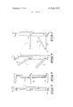
- FIG. 4 is a side elevation showing details of two cantilevered beams in retracted position
- FIG. 5 is an end elevation of a view shown at FIG. 4;
- FIG. 6 is a side elevation showing beams being opened
- FIG. 7 is an additional view showing the beams being opened
- FIG. 8 is a side elevation showing the beams in their fully extended position
- FIG. 9 is a detailed view showing the manner of mounting a beam as well as the fixing jack.
- FIG. 10 is a side elevation of a modular unit
- FIG. 11 is a front elevation of the modular unit
- FIG. 12 is a sectional view along line 12l2 of FIG. 13;
- FIG. 13 is a sectional view showing a typical floor layout for-a modular unit
- FIG. 14 (on the sheet with FIG. 3) is a sectional view showing details of a modular unit floor
- FIG. 15 is (on the sheet with FIG. 3) is a sectional view showing details of a modular unit wall construction.
- FIG. 1 The general layout of the complete structure can best be seen from FIG. 1 and has a main support foundation 10 underground. From this foundation there arises an outer circular support wall 11 and inner straight support walls 12. Supported by these walls are basement floors 13 as well as above ground floors 14.
- the three underground floors 13 can serve as tenant garages and can also connect to underground rapid transit systems.
- Various conduits are shown on the foundation l0 and these can include pneumatic parcel delivery systems, central heating and cooling lines, sewer connections, electricity mains, garbage collection systems, etc.
- elevator shafts I5 In an inner core formed between inner support walls 12 are elevator shafts I5 and between the opposite elevator shafts are open lobby areas 16. Surrounding this central elevator and lobby area is a large service area 17 in which an infinite variety of different facilitates can be provided on different floors of a structure. For instance, certain floors may contain school classrooms, other floors may contain recreational areas, gymnasiums, swimming pools, etc. Outside the service area 17 is a main circular hallway 18 directly connecting to modular units 20.
- the top of the structure has a roof 19 which can serve as a helicopter flight deck and directly beneath this deck 19 is an open area and a lower deck 21. Supported on this lower deck 21 and travelling in the open area is a crane 22 which, as shown in FIG; 1, can be used for hoisting a modular unit either into or out of position in the structure. This crane can also be used for firefighting, to support a suspended gantry for window cleaning and evacuation of occupants in times of emergency. I
- the service tower can contain many different facilitates and, for a high-rise structure it is convenient to include service elevators 23 with service rooms 24 connected thereto on each floor. These service elevators can be used for deliveries to tenants in the structure, for removal of garbage and refuse etc.
- a floor plan of one arrangement of the service tower is shown in FIG. 3 with a swimming pool being shown by the reference numeral 25 on one side of the tower and gymnasiums 26 on the opposite side.
- the inner circular wall 27 divides the service area from the main corridor 18 for the living units.
- Doorways 30 connect the service area with the corridor 18 and additional doorways 31 in outer wall 11 connect this corridor to the units 20.
- the outer wall 1 1 can also contain a variety of services, such as sewer mains, water mains, electrical conduits and garbage chutes.
- Each unit 20 can be connected to these services via suitable metering devices installed for each unit.
- the most important feature of the present invention is the cantilevered support arrangement for holding the individual modular units in position on the service and support tower. Details of this are illustrated in FIGS. 4 to 9. It will be seen that the outer wall of the supporting tower, which will usually be reinforced concrete, has projecting outwardly therefrom reinforced support ledges 32. Articulated support beams 33are mounted on these ledges 32 to support the modular units 20.
- Each beam 33 has an inner member 34 and an outer member 35.
- the inner member 34 is pivotally mounted' on the top face of ledge 32 by connector 36 and the other end of this beam 34 is connected to the end of beam 35 by means of pivotal connector 37.
- FIG. 4 the beam 33 is shown in folded position nested between a pair of ledges 32 and against the wall 11.
- the beams are preferably inclined upwardly very slightly, e.g. about 34, to avoid slippage of a unit away from the tower and to assist in the creation and maintenance of a suitable load center of the unit on the supporting beams.
- a jack 38 Positioned beside the beam 33 in FIG. 5 is shown a jack 38 and this is movably supported from the top on a track mechanism 45. When the beam 33 has assumed its fully extended position as shown in FIG. 8, the jack 38 is moved laterally along the track so that it is positioned directly above the inner end of beam 33.
- the jack has a main housing 40 with an internal thread at the lower end into which turns a jack screw 41.
- a pad 42 is provided on the lower end of screw 41 and this pad 42 rests on the upper face of beam 33.
- the screw 41 With the jack 38 in position directly over beam 33, the screw 41 is turned so as to apply pressure on the beam and provide a rigid cantilevered support for the beam between a pair of ledges 32.
- plates 43 can be bolted between the ledge mounted at the joint between the portions 34 and 35 of beam 33.
- FIGS. to 13 Details of a typical modular unit 20 are illustrated in FIGS. to 13. Each unit is manufactured with a lightweight insulated outer shell 50 supported on a rigid reinforced floor structure 54. Longitudinal recesses 51 are provided in the floor structure to receive the supporting beams 33.
- the inner end of the modular units is enclosed by inner wall 59 and this wall contains the main entrance 31 to the modular unit.
- This entrance has a heavy steel frame 60 with holes 61 therein and a corresponding heavy steel frame is provided in the mating doorway in the tower wall 11.
- bolts are inserted through the holes 61 so as to assure a tight connection between the modular unit and the tower.
- the opening in the tower wall forms a window or door framed by a steel profile which is ready to receive a modular unit.
- FIG. 13 a typical three bedroom apartment layout is shown in FIG. 13.
- the unit has a kitchen 62, a living room 63 and a pair of small bedrooms 65 divided by a dividing wall 64.
- a master bedroom 67 is separated from the living room by dividing wall 66 and a bathroom 68 is provided near the entrance.
- the floor structure 54 for the modular unit is shown in detail in FIG. 14 from which it will be seen to have a main structural plastic portion 70 with a subfloor 71 and a finished floor 72.
- the floor structure is reinforced by steel reinforcing beams 73 and contains large openings 74 which are filled with insulating material 75. These openings 74 can also be used for other purposes such as for carrying a drain pipe 76.
- the floor structure contains an edge recess into which fits a heavy steel Z-profile supporting beam 77.
- Ball bearing steel wheels 78 are mounted on the reinforcing beams 77 and the wheels 78 travel on the support beams 33, thus easing the positioning of the modular units against the support tower.
- the walls of a modular unit can be of a similar construction to the floors with a main structural plastic portion 79 having an outer finished face 80 and inner wall finishes 84.
- structural reinforcing members 81 are provided and insulation filled spaces 82. These insulation filled spaces in the walls can be conveniently used for such purposes as installing electric outlets 83 and carrying the electrical wiring.
- a support and service tower for supporting a plurality of independent modular building units to form a multistorey building, said tower comprising a generally vertical column mounted on the ground and a series of cantilever support beams which are pivotally mounted on horizontal support ledges on the service tower, said support beams being capable of swinging between a retracted vertical position against the service tower wall and a horizontal extended position for receiving and supporting independent enclosed modular building units, and press means for pressing the pivotally mounted end of a beam against said ledge when the beam is in its extended position.
- a tower according to claim 1 wherein the press means is a screw jack which presses the pivotally mounted end of a beam against the horizontal support ledge when the beam is in its extended position.
- a tower according to claim 5 having an outer circular support wall and inner straight support walls.
- a tower according to claim 5 having a rotatably mounted crane unit at the top thereof for installing and removing modular units.
- a tower according to claim 5 having truncated sector shaped modular units mounted on said support beams.
- each modular unit is rigidly fastened to the outer circular support wall by being bolted to a heavy steel frame surrounding a unit connecting doorway in the tower outer wall.
Landscapes
- Engineering & Computer Science (AREA)
- Architecture (AREA)
- Physics & Mathematics (AREA)
- Electromagnetism (AREA)
- Civil Engineering (AREA)
- Structural Engineering (AREA)
- Conveying And Assembling Of Building Elements In Situ (AREA)
Abstract
A support and service tower is described for supporting a plurality of independent modular building units to form a multistorey building. The tower of the invention comprises a generally vertical column mounted on the ground and a series of cantilevered support means mounted on this column. The support means are capable of assuming a retracted vertical position and an extended horizontal position for supporting independent modular building units. The cantilevered support means are preferably in the form of beams which are pivotally mounted on a horizontal support on the service tower and these can be swung from a vertical retract position against the service tower wall and a horizontal extended position for receiving and supporting a modular building unit. These beams can also contain additional hinges along their length to assist in folding them in a compact manner in retracted position against the side of the tower.
Description
United States Patent 1 Drucker [54] MODULAR BUILDING AND SERVICE TOWER THEREFOR [76] Inventor: Ernest R. Drucker, 86 Saginaw Crescent, P.O. Box 5105, Ottawa, Ontario, Canada [22] Filed: Oct. 21, 1971 [21] Appl. No.: 191,510
[30] Foreign Application Priority Data Oct. 26, 1970 Canada ..096530 [52] U.S. Cl. ..52/126, 52/73, 52/79, 52/236, 52/237 [51] Int. Cl. ..E04h l/04 [58] Field of Search ..52/79, 69, 236, 237, 52/73, 283, 122, 126
[56] References Cited UNITED STATES PATENTS 3,402,515 9/1968 Rainaut ..52/236 FOREIGN PATENTS OR APPLICATIONS 558,925 7/1957 Belgium ..52/236 1 May 22, 1973 Primary Examiner.lohn E. Murtagh AttorneyPeter Kirby et al.
[57] ABSTRACT A support and service tower is described for supporting a plurality of independent modular building units to form a multistorey building. The tower of the invention comprises a generally vertical column mounted on the ground and a series of cantilevered support means mounted on this column. The support means are capable of assuming a retracted vertical position and an extended horizontal position for supporting independent modular building units.
The cantilevered support means are preferably in the form of beams which are pivotally mounted on a horizontal support on the service tower and these can be swung from a vertical retract position against the service tower wall and a horizontal extended position for receiving and supporting a modular building unit. These beams can also contain additional hinges along their length to assist in folding them in a compact manner in retracted position against the side of the tower.
9 Claims, 15 Drawing Figures PATENTED HAY 2 2 I973 SHEET 1 UF 5 PATENTEM- 3,733,763
SHEET 2 [1F 5 MODULAR BUILDING AND SERVICE TOWER THEREFOR This invention relates to multiple unit buildings formed of a plurality of modular building units supported on a support and service tower, as well as to the support and service tower itself.
In North America the steadily increasing population, combined with decreasing land availability and very high home construction costs means that more and more the trend is toward multi-unit dwellings. The people of this continent have, of course, long been oriented to the concept of owning their own homes and this becomes quite impossible as the costs ofindividual dwelling units become more and more prohibitive. The result is that people have to give up their idea of owning their own home and instead rent a unit in a multi-unit structure.
Very recently a compromise situation has been developing in the so-called condominium housing where an individual becomes owner of a single unit within a multi-unit structure. This clearly does give some benefits of home ownership, but at the same time there are many problems, such as the fact that there is no way of changing the individual unit since it is an integral part of the total structure.
With the very high material and labor costs involved in the construction of dwelling units, there is also a trend now towards greater use of prefabricating shops for the prefabrication of whole components of a dwelling unit. For example, it is now not uncommon to prefabricate an entire bathroom unit or bathroom and kitchen unit and simply install these directly into the dwelling unit itself. This concept has now reached the stage where entire apartments or hotel rooms with all plumbing, electric wiring etc. are pre-assembled in a factory and then transported to the building site in this preassembled form and simply placed into position in the building structure. There are obviously many advantages in factory construction of dwelling units, such as making it possible to utilize molded plastic components for walls, doors, etc., which would normally be constructed from wood, as well as great labor cost savings in adopting mass production prefabrication techniques.
However, these prefabricated units are normally permanently installed into a structure and become an integral part of the structure. There have, on the other hand, been some suggestions of providing a support structure for prefabricated units, to which the prefabricated units would be detachably connected. Such an arrangement would make it possible for a unit owner to move his unit to a new location, sell his individual unit or buy a new unit for his existing location.
One such support structure is described in Hammond U.S. Pat. No. 2,499,498 issued Mar. 7, 1950, in which a regular building structure is provided with empty spaces into which prefabricated building units were inserted. This has the obvious limitation that the building units themselves are absolutely fixed as to dimensions, style, etc., since they must fit within a fixed rectangular opening.
A more recent development of this conceptis described in Canadian Patent No. 718,143 issued Sept. 21, 1965. [n this structure a central support and service tower is provided with a cantilevered support device mounted on the top of the tower. From this cantilevered support device cables are provided ,extending downwardly and individual modular building units are then suspended from these cables. This system also has some very obvious disadvantages in that the support cables for each building unit must pass directly through all of the units above it. This means that for a multilevel building the number of cables keeps increasing so that the uppermost building unit may have a large number of cables passing therethrough. In addition to this difficulty, it will also be evident that it is by no means an easy matter to either insert or remove a building unit from a location part way up the tower.
There is, therefore, a need for a structure of the type shown in the above Canadian patent but in which the individual building units can be firmly fixedto the support tower and can also be easily removed for transportation to another site.
According to this invention a support and service tower is provided for supporting a plurality of independent modular building units to form a multi-storey building. The tower of the invention comprises a generally vertical column mounted on the ground and a series of cantilevered support means mounted on this column. The support means are capable of assuming a retracted vertical position and an extended horizontal position for supporting independent modular building units.
The cantilevered support means are preferably in the form of beams which are pivotally mounted on a horizontal support on the service tower and these can be swung from a vertical retract position against the service tower wall and a horizontal extended position for receiving and supporting a modular building unit. These beams can also contain additional hinges along their length to assist in folding them in a compact manner in retracted position against the side of the tower.
According to a particularly preferred embodiment of the invention a jack arrangement is provided in association with each support beam, this jack being arranged to press the cantilevered beam rigidly against the support surface on which it is pivotally mounted. This rigidly holds the extended beam in position.
The service tower as well as the individual modular units can assume an almost infinite variety of shapes provided that the tower and unit designs are compatible with each other. The most economical arrangement is to provide a circular tower with a series of modular building units of truncated sector cross-section surrounding the tower. With the circular configuration it will be appreciated that the cantilevered beams in extended position will project radially and special recesses can be provided in the floor of each modular unit within which these radial beams will rest. It will further be appreciated that with the circular configuration the tower can be a complete circle with modular units surrounding it or it may form a segment of a circle, e.g. a semi-circle, with modular units being mounted only on the curving wall.
The folding support beam arrangement of this invention has the great advantage that from the aesthetic standpoint it does not matter whether the support and service tower has all of its position filled..Thus, when these beams are folded out of sight against the wall of the service tower, there is nothing unsightly left in view. With the previous designs not only did a missing unit create a very unsightly situation because the support arrangement for it remained in view but also the pres- 3 ent arrangement permits the installation and removal of individual units with the greatest of ease.
Moreover, these beams 'make it possible for an individual structural unit to be several storeys in height and also to cover several lateral positionsalong with the service tower.
The invention will become apparent from the following description of one embodiment thereof, reference being had to the attached drawings in which:
FIG. 1 is a sectional view of a modular building structure constructed in accordance with the principles of the present invention;
FIG. 2 is a horizontal sectional view, taken along the plane indicated at 22 in FIG. 1;
FIG. 3 is a horizontal sectional view showing details of one embodiment of the service tower;
FIG. 4 is a side elevation showing details of two cantilevered beams in retracted position;
FIG. 5 is an end elevation of a view shown at FIG. 4;
FIG. 6 is a side elevation showing beams being opened;
FIG. 7 is an additional view showing the beams being opened;
FIG. 8 is a side elevation showing the beams in their fully extended position;
FIG. 9 is a detailed view showing the manner of mounting a beam as well as the fixing jack;
FIG. 10 is a side elevation of a modular unit;
FIG. 11 is a front elevation of the modular unit;
FIG. 12 is a sectional view along line 12l2 of FIG. 13;
FIG. 13 is a sectional view showing a typical floor layout for-a modular unit;
FIG. 14 (on the sheet with FIG. 3) is a sectional view showing details of a modular unit floor; and
FIG. 15 is (on the sheet with FIG. 3) is a sectional view showing details of a modular unit wall construction.
The general layout of the complete structure can best be seen from FIG. 1 and has a main support foundation 10 underground. From this foundation there arises an outer circular support wall 11 and inner straight support walls 12. Supported by these walls are basement floors 13 as well as above ground floors 14.
The three underground floors 13 can serve as tenant garages and can also connect to underground rapid transit systems. Various conduits are shown on the foundation l0 and these can include pneumatic parcel delivery systems, central heating and cooling lines, sewer connections, electricity mains, garbage collection systems, etc.
In an inner core formed between inner support walls 12 are elevator shafts I5 and between the opposite elevator shafts are open lobby areas 16. Surrounding this central elevator and lobby area is a large service area 17 in which an infinite variety of different facilitates can be provided on different floors of a structure. For instance, certain floors may contain school classrooms, other floors may contain recreational areas, gymnasiums, swimming pools, etc. Outside the service area 17 is a main circular hallway 18 directly connecting to modular units 20.
The top of the structure has a roof 19 which can serve as a helicopter flight deck and directly beneath this deck 19 is an open area and a lower deck 21. Supported on this lower deck 21 and travelling in the open area is a crane 22 which, as shown in FIG; 1, can be used for hoisting a modular unit either into or out of position in the structure. This crane can also be used for firefighting, to support a suspended gantry for window cleaning and evacuation of occupants in times of emergency. I
As mentioned above, the service tower can contain many different facilitates and, for a high-rise structure it is convenient to include service elevators 23 with service rooms 24 connected thereto on each floor. These service elevators can be used for deliveries to tenants in the structure, for removal of garbage and refuse etc. A floor plan of one arrangement of the service tower is shown in FIG. 3 with a swimming pool being shown by the reference numeral 25 on one side of the tower and gymnasiums 26 on the opposite side. The inner circular wall 27 divides the service area from the main corridor 18 for the living units. Doorways 30 connect the service area with the corridor 18 and additional doorways 31 in outer wall 11 connect this corridor to the units 20. The outer wall 1 1 can also contain a variety of services, such as sewer mains, water mains, electrical conduits and garbage chutes. Each unit 20 can be connected to these services via suitable metering devices installed for each unit.
The most important feature of the present invention is the cantilevered support arrangement for holding the individual modular units in position on the service and support tower. Details of this are illustrated in FIGS. 4 to 9. It will be seen that the outer wall of the supporting tower, which will usually be reinforced concrete, has projecting outwardly therefrom reinforced support ledges 32. Articulated support beams 33are mounted on these ledges 32 to support the modular units 20.
Each beam 33 has an inner member 34 and an outer member 35. The inner member 34 is pivotally mounted' on the top face of ledge 32 by connector 36 and the other end of this beam 34 is connected to the end of beam 35 by means of pivotal connector 37. In FIG. 4 the beam 33 is shown in folded position nested between a pair of ledges 32 and against the wall 11. When the beam is put in use to support modular units, it is unfolded as shown in FIGS. 6, 7 and 8 so as to assume a fully extended horizontal position as shown in FIG. 8. In fully extended position the beams are preferably inclined upwardly very slightly, e.g. about 34, to avoid slippage of a unit away from the tower and to assist in the creation and maintenance of a suitable load center of the unit on the supporting beams.
Positioned beside the beam 33 in FIG. 5 is shown a jack 38 and this is movably supported from the top on a track mechanism 45. When the beam 33 has assumed its fully extended position as shown in FIG. 8, the jack 38 is moved laterally along the track so that it is positioned directly above the inner end of beam 33.
The relationship of the beam and jack is shown in greater detail in FIG. 9 from which it will be seen that the jack has a main housing 40 with an internal thread at the lower end into which turns a jack screw 41. A pad 42 is provided on the lower end of screw 41 and this pad 42 rests on the upper face of beam 33. With the jack 38 in position directly over beam 33, the screw 41 is turned so as to apply pressure on the beam and provide a rigid cantilevered support for the beam between a pair of ledges 32. To provide additional strengthening of the connections, plates 43 can be bolted between the ledge mounted at the joint between the portions 34 and 35 of beam 33.
Details of a typical modular unit 20 are illustrated in FIGS. to 13. Each unit is manufactured with a lightweight insulated outer shell 50 supported on a rigid reinforced floor structure 54. Longitudinal recesses 51 are provided in the floor structure to receive the supporting beams 33.
With a circular structure and all of the spaces filled, it will be evident that all natural outside lighting for the units must be obtained from the outer walls. To take best advantage of this, additional short outer radial walls 49 are provided, these being spaced from the main radial walls 50. The outer radial walls 49 are joined by end walls 52 containing window units 53. Between radial walls 49 and 50 are positioned porches 69 and between these porches and the interior of the modular units are dividing walls 55. These dividing walls contain doors 56 and window units 57 while a protective wall 58 encloses the outer edge of the porch.
The inner end of the modular units is enclosed by inner wall 59 and this wall contains the main entrance 31 to the modular unit. This entrance has a heavy steel frame 60 with holes 61 therein and a corresponding heavy steel frame is provided in the mating doorway in the tower wall 11. When a modular unit is in position against the tower, bolts are inserted through the holes 61 so as to assure a tight connection between the modular unit and the tower. When the unit is not installed the opening in the tower wall forms a window or door framed by a steel profile which is ready to receive a modular unit.
It will be appreciated that a large variety of floor layouts are possible for these modular units and a typical three bedroom apartment layout is shown in FIG. 13. Thus, it will be seen that the unit has a kitchen 62, a living room 63 and a pair of small bedrooms 65 divided by a dividing wall 64. A master bedroom 67 is separated from the living room by dividing wall 66 and a bathroom 68 is provided near the entrance.
The floor structure 54 for the modular unit is shown in detail in FIG. 14 from which it will be seen to have a main structural plastic portion 70 with a subfloor 71 and a finished floor 72. The floor structure is reinforced by steel reinforcing beams 73 and contains large openings 74 which are filled with insulating material 75. These openings 74 can also be used for other purposes such as for carrying a drain pipe 76.
The floor structure contains an edge recess into which fits a heavy steel Z-profile supporting beam 77. Ball bearing steel wheels 78 are mounted on the reinforcing beams 77 and the wheels 78 travel on the support beams 33, thus easing the positioning of the modular units against the support tower.
The walls of a modular unit can be of a similar construction to the floors with a main structural plastic portion 79 having an outer finished face 80 and inner wall finishes 84. Once again structural reinforcing members 81 are provided and insulation filled spaces 82. These insulation filled spaces in the walls can be conveniently used for such purposes as installing electric outlets 83 and carrying the electrical wiring.
The embodiments of the invention in which an exclusive property or privilege is claimed are defined as follows:
l. A support and service tower for supporting a plurality of independent modular building units to form a multistorey building, said tower comprising a generally vertical column mounted on the ground and a series of cantilever support beams which are pivotally mounted on horizontal support ledges on the service tower, said support beams being capable of swinging between a retracted vertical position against the service tower wall and a horizontal extended position for receiving and supporting independent enclosed modular building units, and press means for pressing the pivotally mounted end of a beam against said ledge when the beam is in its extended position.
2. A tower according to claim 1 wherein the beams are articulated along their length by means of hinge connections.
3. A tower according to claim 1 wherein the press means is a screw jack which presses the pivotally mounted end of a beam against the horizontal support ledge when the beam is in its extended position.
4. A tower according to claim 3 wherein the jack is laterally movable.
5. A tower according to claim 1 wherein the tower is circular with the support beams mounted radially thereon.
6. A tower according to claim 5 having an outer circular support wall and inner straight support walls.
7. A tower according to claim 5 having a rotatably mounted crane unit at the top thereof for installing and removing modular units.
8. A tower according to claim 5 having truncated sector shaped modular units mounted on said support beams.
9. A tower according to claim 8 wherein each modular unit is rigidly fastened to the outer circular support wall by being bolted to a heavy steel frame surrounding a unit connecting doorway in the tower outer wall.
Claims (9)
1. A support and service tower for supporting a plurality of independent modular building units to form a multistorey building, said tower comprising a generally vertical column mounted on the ground and a series of cantilever support beams which are pivotally mounted on horizontal support ledges on the service tower, said support beams being capable of swinging between a retracted vertical position against the service tower wall and a horizontal extended position for receiving and supporting independent enclosed modular building units, and press means for pressing the pivotally mounted end of a beam against said ledge when the beam is in its extended position.
2. A tower according to claim 1 wherein the beams are articulated along their length by means of hinge connections.
3. A tower according to claim 1 wherein the press means is a screw jack which presses the pivotally mounted end of a beam against the horizontal support ledge when the beam is in its extended position.
4. A tower according to claim 3 wherein the jack is laterally movable.
5. A tower according to claim 1 wherein the tower is circular with the support beams mounted radially thereon.
6. A tower according to claim 5 having an outer circular support wall and inner straight support walls.
7. A tower according to claim 5 having a rotatably mounted crane unit at the top thereof for installing and removing modular units.
8. A tower according to claim 5 having truncated sector shaped modular units mounted on said support beams.
9. A tower according to claim 8 wherein each modular unit is rigidly fastened to the outer circular support wall by being bolted to a heavy steel frame surrounding a unit connecting doorway in the tower outer wall.
Applications Claiming Priority (1)
| Application Number | Priority Date | Filing Date | Title |
|---|---|---|---|
| CA96530 | 1970-10-26 |
Publications (1)
| Publication Number | Publication Date |
|---|---|
| US3733763A true US3733763A (en) | 1973-05-22 |
Family
ID=4087877
Family Applications (1)
| Application Number | Title | Priority Date | Filing Date |
|---|---|---|---|
| US00191510A Expired - Lifetime US3733763A (en) | 1970-10-26 | 1971-10-21 | Modular building and service tower therefor |
Country Status (3)
| Country | Link |
|---|---|
| US (1) | US3733763A (en) |
| JP (1) | JPS5139361Y2 (en) |
| CA (1) | CA922081A (en) |
Cited By (14)
| Publication number | Priority date | Publication date | Assignee | Title |
|---|---|---|---|---|
| US4640214A (en) * | 1985-01-18 | 1987-02-03 | Bruns John H | Modular multi-storage building |
| US4656799A (en) * | 1986-04-28 | 1987-04-14 | Stratatowers Corp | Super high-rise buildings |
| US4726316A (en) * | 1985-01-18 | 1988-02-23 | Bruns John H | Floating storage building |
| US4736557A (en) * | 1986-04-28 | 1988-04-12 | Stratatowers Corporation | Super high-rise buildings |
| US4817345A (en) * | 1982-07-15 | 1989-04-04 | Mcglew John J | Building having movable restaurant |
| WO2002097206A1 (en) * | 2001-06-01 | 2002-12-05 | Bluebase | Accommodation system |
| US20060230691A1 (en) * | 2005-01-19 | 2006-10-19 | Fisher David H | Rotatable building structure |
| US20100090465A1 (en) * | 2008-10-15 | 2010-04-15 | Robert Eric Heidel | Process of installing prefabricated sections of pressurized and/or non-pressurized fluid-, utility-, and/or matter-carrying and encapsulated mediums with turbine systems attached into medium systems |
| WO2015097226A3 (en) * | 2013-12-23 | 2015-09-24 | GEIGER, Gunter, Grant | Building, in particular a hospital |
| DE102014010736A1 (en) * | 2014-07-23 | 2016-01-28 | Feldmann+Schultchen Design Studios Gmbh | Buildings with public traffic area |
| WO2016046770A1 (en) | 2014-09-23 | 2016-03-31 | Dinamikpumpkin, Lda | Modular system for fast connection of habitable modules |
| JP2020084624A (en) * | 2018-11-28 | 2020-06-04 | 三井住友建設株式会社 | Multiple dwelling house |
| US12116771B2 (en) | 2020-12-31 | 2024-10-15 | Mitek Holdings, Inc. | Rapid assembly construction modules and methods for use |
| US12201563B2 (en) | 2019-10-03 | 2025-01-21 | EIR Healthcare Holdings, Inc. | Modular insert for a patient room |
Families Citing this family (1)
| Publication number | Priority date | Publication date | Assignee | Title |
|---|---|---|---|---|
| US4676037A (en) * | 1985-07-02 | 1987-06-30 | Toshio Nakasone | Building and method of construction |
-
1970
- 1970-10-26 CA CA922081A patent/CA922081A/en not_active Expired
-
1971
- 1971-10-21 US US00191510A patent/US3733763A/en not_active Expired - Lifetime
- 1971-10-26 JP JP1971098715U patent/JPS5139361Y2/ja not_active Expired
Cited By (17)
| Publication number | Priority date | Publication date | Assignee | Title |
|---|---|---|---|---|
| US4817345A (en) * | 1982-07-15 | 1989-04-04 | Mcglew John J | Building having movable restaurant |
| US4640214A (en) * | 1985-01-18 | 1987-02-03 | Bruns John H | Modular multi-storage building |
| US4726316A (en) * | 1985-01-18 | 1988-02-23 | Bruns John H | Floating storage building |
| US4656799A (en) * | 1986-04-28 | 1987-04-14 | Stratatowers Corp | Super high-rise buildings |
| US4736557A (en) * | 1986-04-28 | 1988-04-12 | Stratatowers Corporation | Super high-rise buildings |
| WO2002097206A1 (en) * | 2001-06-01 | 2002-12-05 | Bluebase | Accommodation system |
| US20060230691A1 (en) * | 2005-01-19 | 2006-10-19 | Fisher David H | Rotatable building structure |
| US20100090465A1 (en) * | 2008-10-15 | 2010-04-15 | Robert Eric Heidel | Process of installing prefabricated sections of pressurized and/or non-pressurized fluid-, utility-, and/or matter-carrying and encapsulated mediums with turbine systems attached into medium systems |
| WO2015097226A3 (en) * | 2013-12-23 | 2015-09-24 | GEIGER, Gunter, Grant | Building, in particular a hospital |
| CN106164388A (en) * | 2013-12-23 | 2016-11-23 | 冈特·格兰特·盖格 | buildings, especially hospitals |
| US10167645B2 (en) | 2013-12-23 | 2019-01-01 | Gunter Geiger | Building, in particular a hospital |
| US10883287B2 (en) | 2013-12-23 | 2021-01-05 | Gunter Geiger | Building, in particular a hospital |
| DE102014010736A1 (en) * | 2014-07-23 | 2016-01-28 | Feldmann+Schultchen Design Studios Gmbh | Buildings with public traffic area |
| WO2016046770A1 (en) | 2014-09-23 | 2016-03-31 | Dinamikpumpkin, Lda | Modular system for fast connection of habitable modules |
| JP2020084624A (en) * | 2018-11-28 | 2020-06-04 | 三井住友建設株式会社 | Multiple dwelling house |
| US12201563B2 (en) | 2019-10-03 | 2025-01-21 | EIR Healthcare Holdings, Inc. | Modular insert for a patient room |
| US12116771B2 (en) | 2020-12-31 | 2024-10-15 | Mitek Holdings, Inc. | Rapid assembly construction modules and methods for use |
Also Published As
| Publication number | Publication date |
|---|---|
| CA922081A (en) | 1973-03-06 |
| JPS47272U (en) | 1972-06-26 |
| JPS5139361Y2 (en) | 1976-09-27 |
Similar Documents
| Publication | Publication Date | Title |
|---|---|---|
| US3733763A (en) | Modular building and service tower therefor | |
| US3643390A (en) | Modular building structure | |
| US3550334A (en) | Plural story building comprising superimposed box-shaped dwelling units | |
| US3503170A (en) | Modular post-tensioned overlapped staggered building construction | |
| US3452493A (en) | Elevated modular building construction | |
| US4759158A (en) | Set of prefabricated construction elements | |
| EP3455422A1 (en) | Prefabricated building module | |
| KR20150036571A (en) | Modular building | |
| US3402515A (en) | Folding multi-storeyed buildings | |
| US3902287A (en) | Dwelling construction system | |
| US2795014A (en) | Complete factory produced dwelling | |
| US3738069A (en) | Modular building construction | |
| US3945157A (en) | Prefabricated wall elements | |
| AU2023366048B2 (en) | A modular multi-storey building and a method for the construction thereof | |
| US3226727A (en) | Suspended module buildings | |
| US3331168A (en) | Suspended module buildings | |
| US3884001A (en) | Split-level townhouse | |
| US3302340A (en) | Staggered multilevel apartment system with elevators | |
| US2058543A (en) | Prefabricated dwelling | |
| CA2046217A1 (en) | Residential building and a building unit for same | |
| US3755973A (en) | Modular building system | |
| GB2266907A (en) | Portable secure accommodation unit | |
| US4202146A (en) | Transportable module for trilevel dwelling | |
| JP2023012790A (en) | multi-storey wooden house | |
| JP3584979B2 (en) | housing complex |