US3716952A - Loading device - Google Patents
Loading device Download PDFInfo
- Publication number
- US3716952A US3716952A US00171620A US3716952DA US3716952A US 3716952 A US3716952 A US 3716952A US 00171620 A US00171620 A US 00171620A US 3716952D A US3716952D A US 3716952DA US 3716952 A US3716952 A US 3716952A
- Authority
- US
- United States
- Prior art keywords
- workpiece
- machine tool
- chute
- loading
- holding
- Prior art date
- Legal status (The legal status is an assumption and is not a legal conclusion. Google has not performed a legal analysis and makes no representation as to the accuracy of the status listed.)
- Expired - Lifetime
Links
- 241000282472 Canis lupus familiaris Species 0.000 claims description 12
- 238000007599 discharging Methods 0.000 claims description 4
- 239000012530 fluid Substances 0.000 description 20
- 230000006835 compression Effects 0.000 description 10
- 238000007906 compression Methods 0.000 description 10
- 230000033001 locomotion Effects 0.000 description 7
- 238000002485 combustion reaction Methods 0.000 description 2
- 238000012790 confirmation Methods 0.000 description 2
- 230000001276 controlling effect Effects 0.000 description 2
- 101100264195 Caenorhabditis elegans app-1 gene Proteins 0.000 description 1
- 230000000295 complement effect Effects 0.000 description 1
- 239000013256 coordination polymer Substances 0.000 description 1
- 238000012986 modification Methods 0.000 description 1
- 230000004048 modification Effects 0.000 description 1
- NJPPVKZQTLUDBO-UHFFFAOYSA-N novaluron Chemical compound C1=C(Cl)C(OC(F)(F)C(OC(F)(F)F)F)=CC=C1NC(=O)NC(=O)C1=C(F)C=CC=C1F NJPPVKZQTLUDBO-UHFFFAOYSA-N 0.000 description 1
- 230000001105 regulatory effect Effects 0.000 description 1
- 230000000717 retained effect Effects 0.000 description 1
Images


Classifications
-
- B—PERFORMING OPERATIONS; TRANSPORTING
- B23—MACHINE TOOLS; METAL-WORKING NOT OTHERWISE PROVIDED FOR
- B23Q—DETAILS, COMPONENTS, OR ACCESSORIES FOR MACHINE TOOLS, e.g. ARRANGEMENTS FOR COPYING OR CONTROLLING; MACHINE TOOLS IN GENERAL CHARACTERISED BY THE CONSTRUCTION OF PARTICULAR DETAILS OR COMPONENTS; COMBINATIONS OR ASSOCIATIONS OF METAL-WORKING MACHINES, NOT DIRECTED TO A PARTICULAR RESULT
- B23Q7/00—Arrangements for handling work specially combined with or arranged in, or specially adapted for use in connection with, machine tools, e.g. for conveying, loading, positioning, discharging, sorting
- B23Q7/16—Loading work on to conveyors; Arranging work on conveyors, e.g. varying spacing between individual workpieces
- B23Q7/18—Orienting work on conveyors
-
- B—PERFORMING OPERATIONS; TRANSPORTING
- B23—MACHINE TOOLS; METAL-WORKING NOT OTHERWISE PROVIDED FOR
- B23Q—DETAILS, COMPONENTS, OR ACCESSORIES FOR MACHINE TOOLS, e.g. ARRANGEMENTS FOR COPYING OR CONTROLLING; MACHINE TOOLS IN GENERAL CHARACTERISED BY THE CONSTRUCTION OF PARTICULAR DETAILS OR COMPONENTS; COMBINATIONS OR ASSOCIATIONS OF METAL-WORKING MACHINES, NOT DIRECTED TO A PARTICULAR RESULT
- B23Q7/00—Arrangements for handling work specially combined with or arranged in, or specially adapted for use in connection with, machine tools, e.g. for conveying, loading, positioning, discharging, sorting
- B23Q7/04—Arrangements for handling work specially combined with or arranged in, or specially adapted for use in connection with, machine tools, e.g. for conveying, loading, positioning, discharging, sorting by means of grippers
Definitions
- ABSTRACT A device for automatically loading a non-circular workpiece onto a machine tool in a preselected angular position.
- the device comprises an indexing mechanism for indexing the workpiece into the proper angular position, a holding mechanism for holding the indexed workpiece, and a shifting mechanism for moving the workpiece from the holding mechanism to a clamping fixture of the machine tool without ,any deviation from the established proper angular position.
- the present invention is related generally to a device for loading workpieces, and more particularly to an improved device for loading a non-circular workpiece in a proper angular relationship with respect to a given machine tool.
- non-circular workpiece When a non-circular workpiece is turned or ground on a machine tool, it generally must be loaded having a predetermined angular relationship with a clamping fixture of the machine tool.
- the non-circular workpiece is a piston for an internal combustion engine, which is one of the most sophisticated parts in an industrial field and is oval in shape at the skirt portion thereof, and thus, should be ground by a particular piston grinding machine which grinds the skirt portion duplicating a master cam.
- an essential requirement is to establish a predetermined angular relationship between the master cam and the workpiece.
- a device for automatically loading such a non-circular workpiece, as the aforedescribed piston, with the required angular relationship relative to the clamping fixture or the master cam of the machine tool has been long needed, and until now such a device has not been successfully developed.
- an object of the present invention to provide a device for automatically loading a non-circular workpiece onto a machine tool in a predetermined angular position relative thereto.
- Another object of the present invention is to provide a device operable for detecting the angular position of a workpiece being received by a machine tool and to arrange the workpiece so that it may be loaded onthe machine tool in a preselected angular relationship therewith.
- Still another object of the present invention is to provide a device capable of shifting a workpiece toward a.
- a still further object of this invention is to provide a device capable of moving workpieces one by one into an indexing mechanism and a holding mechanism of a machine tool.
- FIG. 1 is a schematic view showing the arrangement of a preferred embodiment of a loading device according to the present invention
- FIG. 2 is a detailed sectional view showing a workpiece turning mechanism, taken along the line IIII in FIG. 1;
- FIG. 3 is a top view showing a workpiece charging mechanism in detail
- FIG. 4 is a sectional view showing a workpiece indexing mechanism, taken along the line IV-IV in FIG. 3;
- FIG. 5 is a sectional view showing another embodiment of a workpiece indexing mechanism
- FIG. 6 is a sectional view taken along the line VI-VI in FIG. 5;
- FIG. 7 is a sectional view taken along the line VII- VII in FIG. 3;
- FIG. 8 is a sectional view showing a workpiece shifting mechanism, taken along the line VIII-VIII in FIG.
- FIG. 9 is a sectional view taken along the line IX-IX in FIG. 8.
- FIG. 10 is a sectional view taken along the line X-X in FIG. 9.
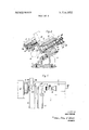
- FIG. 1 a preferred embodiment characterizing the loading of a piston for an internal combustion engine onto a piston grinding machine is briefly described.
- a head stock 2 and a shifting mechanism 3 are mounted on a traverse table 1 of a piston grinding machine in predetermined spaced relation.
- the head stock 2 is provided with a rotatable spindle, not shown, which carries a clamping fixture 4 of a diaphragm type for supporting a piston workpiece W.
- a workpiece turning mechanism 5 is fixed on the traverse table 1 between the head stock 2 and the shifting mechanism 3.
- a workpiece charging mechanism 6 extends from the turning mechanism 5 in a perpendicular with respect to the axis of the spindle of the head stock 2 and a chute 7 parallel therewith for discharging a ground workpiece from the machine is secured on the traverse table 1 under the clamping fixture 4.
- FIG. 2 Mounted on the table I is a pedestal 11 having a supporting block 12 in turn fixed thereon.
- a shaft 13 is rotatably journalled in the supporting block 12 with its axis being oblique to the table I and being arranged so as to intersect the axis of the head stock spindle.
- a pinion 14 is formed on the shaft 13 intermediate the ends thereof being meshingly engaged with a rack 16 formed on the piston rod of a hydraulic actuator 15 provided in the block 12.
- the rack 16 of the hydraulic actuator 15 may be moved back and forth by the pressure fluid being supplied thereto so that the shaft 13 is rotated through a ninety degree turn in one direction or the other.
- the ends of the rotational motions of the shaft 13 may be detected by limit switches 109 and which are respectively actuated by dogs 107 and 108 secured to one end of the shaft 13.
- One arm of an L-shaped bracket 17 is connected to the other end of the shaft 13 and the other arm thereof is provided with a holding mechanism 17a for holding a piston workpiece W being shifted from the workpiece charging mechanism 6.
- a plate member 18 for supporting the workpiece W is fixed to the other arm of the L- shaped bracket 17.
- a pair of gears 19 and 20, shown in FIG. 3, being interengaged with each other, is rotatably carried on the underside of the plate member 18.
- Link arms 21 and 22 are respectively fixedly connected to the gears 19 and 20 at one of the ends thereof and at their other ends are provided with abutments 23 and 24, respectively, for pushing the workpiece W.
- a tension spring 25 is interposed between the free tips of the link arms 21 and 22 so that the abutments 23 and 24 are always urged toward each other or toward the piston workpiece W.
- the axis of the piston workpiece W is perpendicular to the axis of the head stock spindle, and when the bracket 17 is turned by means of the hydraulic actuator through 90 degrees, the axis of the piston workpiece W coincides with the axis of the head stock spindle or the clamping fixture 4.
- a plurality of guide rollers 28 for charging the workpiece W into the holding mechanism 17a are rotatably mounted on the top portion of the bracket 17, being shown in FIGS. 2 and 3.
- a lower chute 31 Fixedly mounted on the supporting block 12 is a lower chute 31 which extends in oblique relationship with the traverse table 1 but is parallel with the axis of the shaft 13. At the middle of the lower chute 31 there is provided an indexing mechanism 8 for indexing the piston workpiece W on the lower chute 31 into a particular angular position.
- An upper chute 33 is mounted on, a pair of panels 32 which are secured to the lower chute 31 at both sides thereof.
- Guide rollers 34 as shown in FIG. 7, are rotatably-mounted in the lower chute 31 at predetermined intervals for transferring the workpiece W.
- a housing 36 Fixedly mounted on the upper chute 33 is a housing 36 having a rotatable shaft 37 provided therein, as
- the shaft 37 protrudes into the inside of the upper chute 33 and, at the lower end thereof, is provided with an engaging piece 38 which may straddle a protruding portion W3 of the skirt portion of the piston workpiece W so that the piston workpiece may be tumed through the engaging piece 38.
- a pinion 39 is provided on the shaft 37 intermediate its ends being meshingly engaged with the rack on a rack piston, not shown, which is slidably contained in a hydraulic actuator 40 and is operative to turn the shaft 37 through 180 so that the piston workpiece W, which is in an opposite angular position, is turned into the required angular position through the engaging piece 38.
- guide rails 35, 35 which are secured to the panels 32, 32, and keep the piston workpiece W with its axis vertically oriented and from being turned from a fixed angular position, are discontinued at the indexing mechanism 8 so that the piston workpiece W may be turned.
- ' hydraulic actuator 41 for lifting the piston workpiece W is fixed to the under side of the lower chute 31 in a position aligned with the shaft 37, and has a piston 42 with a piston rod 43 thereon disposed in a vertical direction therein.
- the piston rod 43 is provided with a supporting block 44 at the top end thereof.
- a locating link 45 which is formed with an engaging portion 46 for engaging a front mark W2 provided at a particular portion of the piston workpiece W to denote the angular position thereof, is pivotably mounted on the end of the supporting block 44 being urged in a counter clockwise direction, as seen in FIG. 4, by a compression spring 47 interposed between the link 45 and the housing of the hydraulic actuator 41 so that the engaging portion 46 is always urged toward the piston workpiece W.
- the counterclockwise rotation of the link 45 is regulated by a stop 48 threadedly engaged with the housing of the hydraulic actuator 41.
- a pair of dogs 49 and 51 facing in opposite directions is adjustably mounted at the lower end of the link 45 and limit switches 50 and 52 for detecting the fact that the piston workpiece W is located in the proper angular position are positioned to be respectively actuated by the dogs 49 and 51.
- the limit switches 50 and 52 are respectively actuated when the engaging portion 46 of the link 45 is and is not engaged with the front mark W2 of the piston workpiece W.
- the hydraulic actuator 40 is operable to turn the workpiece W through to get a proper angular position only when the limit switch 52 is actuated, in other words, when the piston workpiece W is moved down in an improper angular position.
- FIGS. 5 and 6 a second embodiment of an indexing mechanism 8 is illustrated which is applicable to a piston workpiece W not being provided with the side notches W5, W5, described above, in which case the piston workpiece W is slidable down into the indexing mechanism 8 in any angular direction, as described hereinbelow.
- a hydraulic actuator 121 for lifting the piston workpiece W is secured to the under side of the lower chute 31.
- a piston rod 121a of the hydraulic actuator 121 is provided with an enlargement at the top portion thereof.
- an engaging pin 127 and a pin 128 are slidably mounted in axial directions thereof being retained against rotation, respectively, by keyed engagement with the piston rod enlargement.
- the engaging pin 127 is constantly urged upward by a compression spring and is arranged to be engaged with a front mark W2 in the piston workpiece W when the piston workpiece W is brought into the proper angular position and the pin 128 is urged upward by another compression spring and is provided with a bearing type upper surface so that the piston workpiece W may be smoothly turned on the pins 127 and 128.
- a center 129 is provided in the center of the enlargement of the piston rod 121a to support the piston workpiece W at a predetermined position.
- Another hydraulic actuator 124 for turning the piston rod 121a to bring the piston workpiece W into a proper angular position through the engagement of the engaging pin 127 and the front mark W2 is provided in the housing of the hydraulic actuator 121 and has a slidable rack piston 124a therein.
- a pinion 121b is formed on the piston rod 121a and is engaged with the rack on the rack piston 124a.
- the stroke ends of the rack piston 124a are detected by two limit switches 137 and 138 which are respectively actuated by dogs 137a and 138a.
- a rod 126 is connected through the piston 120 of the hydraulic actuator 121 projecting to the outside thereof and is biased downwardly by a compressed spring 125 interposed between the housing of the actuator 121 and the rod 126 for normally holding the piston 120 in a lower position.
- a compressed spring 125 interposed between the housing of the actuator 121 and the rod 126 for normally holding the piston 120 in a lower position.
- an actuator 133 having therein a slidable piston 130 in which a rod 141 is slidably mounted being provided on its lower face with a pushing plate 139 for pushing the piston workpiece W downwardly.
- a nut 135 threadedly engaged with the rod 141 at the ,top end thereof limits the range of up and down motion of the rod '141 with respect to the piston 130.
- a pin 132 mounted on the housing of the actuator 133 engages the pushing plate 139 for preventing the pushing plate 139 from rotation.
- a pair of guide rails 140, 140 are secured to the panels 32, 32 between the indexing mechanism 8 and the holding mechanism 17a so that the piston workpiece W may not be deviated from the proper angular position which has been established by the indexing mechanism.
- brackets In the vicinity of both ends and the middle of the chute 31 there are provided three sets of brackets, 55a, 55b and 550, as shown in FIG. 3, which respectively support front shutters 56 and 56, middle shutters 57 and 57 and rear shutter 58.
- the shutters control the flow of the workpieces W so that the workpiece W is supplied to the workpiece indexing mechanism 8 and holding mechanism 17a one by one.
- the front shutters are fixedly connected by means of pins to link members 59 and 59 which are, in turn, connected to a connecting rod 61 by links 60 and 60.
- the rod 61 is connected to a piston rod 63 of a piston, not shown, which is slidably mounted in a hydraulic actuator 62 mounted on the upper chute 33.
- the shutters 57, 57 of the middle portion are con- 5 nected to the shutters 56, 56 by connecting rods 66, 66
- the piston workpiece W is checked for location in a proper angular position, and if not, then turned into the proper angular position, the piston workpiece W being supported by the lower tips 67, 67 of the shutters 57, 57.
- the rear shutter 58 which is operative to supply the piston workpieces W one by one into the indexing mechanism 8, is connected to one of the middle shutters 57, 57, by means of a connecting rod 68 and its associated linking mechanism 69.
- a bracket 71 Fixedly mounted at the front end of the lower chute 31 is a bracket 71 on which a control link 72 is pivotally mounted.
- the one end of the control link 72 is connected to the front shutter 56 through a connecting rod 73 so that the control link 72 is moved in synchronism with the shutters.
- the other or front end of the control link 72 is arranged to engage a pin 74 press-fitted on one of the abutments 23 and 24, whereby the abutments 23 and 24 are turned to open against the force of the tension spring 25 in conjunction with the motion of the shutters resulting in the piston workpiece W being passed through the front shutters 56, 56 and slidably moved down into the holding mechanism 17a.
- the shifting mechanism may be described referring particularly to FIGS. 8, 9 and 10.
- a housing 76 of the shifting mechanism is mounted on the table 1 and carries a ram 77 being slidable in an axial direction but restrained from rotational motion.
- a supporting member 79 is slidably carried on a bushing 78 secured to the front end of the ram 77 and is normally urged toward the left, as shown in FIGS. 9 and 10, by a compression spring 82 interposed therebetween.
- a ring member 80 is secured to the supporting member 79 and is connected to the bushing 78 by an elastic member 81 which regulates the range of motion of the supporting member 79.
- a control rod 83 Slidably mounted in the supporting member 79 is a control rod 83 having a pair of grooves 84 and 85 in the vicinity of the front end thereof which are oblique with respect to the axis thereof and oppositely directed relative to each other.
- Locating pins 87 and 88 are slidably inserted in a bore 86 perforated in the vicinity of the front end of the supporting member 79 and are guided with each other through guide pins 89 and 89.
- engaging portions 90 and 91 In the interior of the locating pins 87 and 88, there are provided engaging portions 90 and 91 which are respectively engaged with the oblique grooves 84 and 85 of the control rod 83.
- the control rod 83 is connected by a connecting rod 92 to a piston rod 95 of a piston 94 which is slidably positioned in a hydraulic actuator 93 provided at the rear portion of the ram 77.
- the piston 94 is moved by pressurized fluid supplied to the hydraulic actuator 93 to move the control rod 83 back and forth so that the locating pins 87 and 88 may be moved in a radial direction for causing them to engage with and be disengaged from pin holes W4, W4 of the piston workpiece W.
- the axial motion of the piston 94 is controlled by limit switches 113 and 1 14 which are respectively actuated by dogs 111 and 112 on a piston rod 93b secured to one end of the piston 94.
- a first shifting actuator 97 having a piston 98 slidably disposed therein is fixed to a mounting plate 96 secured to the ram 77 at the rear end thereof.
- a second shifting actuator 99 having a slidable piston 100 which is connected to the piston 98 by a rod 101 is provided in the housing 76.
- the movable range of the piston 100 is arranged to be longer than that of the piston 98. Accordingly, the ram 77 may be positioned at three different positions, that is, an original position shown in FIG. 8, a middle position advanced by the actuator 97 and a front position being advanced further by both actuators 97 and 99.
- the piston workpiece W When the ram 77 is located at the middle position, the piston workpiece W may be transferred from the holding mechanism 17a to the ram 77, and when the ram 77 is located at the front position, the piston workpiece W is transferred from the ram 77 to the clamping fixture 4 which holds the workpiece W by clamping pawls L05, 105, and thereafter, the skirt portion of the piston workpiece W is ground by the grinding wheel 106 duplicating the master cam, not shown.
- one piston workpiece W to be ground is clamped to the clamping fixture 4 by the pawls 105, 105, while another workpiece W which is supposed to shift to the clamping fixture 4 is supported by the shifting mechanism 3 in the required angular position by means of the locating pins 87 and 88.
- Another piston workpiece W is held by the holding mechanism 17a, and on the chute 31 still another workpiece W already indexed intothe proper angular position is held by the lower tips 65 and 65 of the shutters 56 and 56 and yet another workpiece about to be indexed by the indexing mechanism 8 is embraced by the lower tips 67 and 67 of the shutters 57 and 57.
- pressurized fluid is supplied to the rear chamber 93b of the actuator 93 to advance the control rod 83 through the piston 94. Accordingly, the locating pins 87 and 88 respectively engaged with the oblique grooves 84 and 85 are retracted radially into the control rod 83 to be thereby disengaged from the pin holes W4, W4 of the piston workpiece W.
- the limit switch 113 When the piston 94 is advanced to the calculated advanced position, the limit switch 113 is actuated by the dog 111 causing a signal to be generated for supplying the pressurized fluid to the rear chamber 97b of the actuator 97 and the front chamber 99a of the actuator 99 so that the shifting ram 77 is retracted to the original position thereof.
- a confirmation signal is produced, whereby the clamping fixture 4 is rotated and the wheel slide is advanced toward the piston workpiece W to perform a grinding operation thereon.
- pressurized fluid is applied to the actuator 15 so that the holding mechanism 17a may be rotated by through rack piston 16, pinion l4 and shaft 13, whereby the axis of the piston workpiece W on the holding mechanism 17a is coincided with the axis of the head spindle and the shifting ram 77.
- the limit switch is actuated by the dog 108 to thereby generate a signal which initiates the supply of pressurized fluid to the front chamber 97a of the actuator 97 to carry the shifting ram 77 to the middle position thereof.
- the supporting member 79 secured to the shifting ram 77 is inserted into the piston workpiece W and thus, through the signal produced when the piston 98 of the actuator 97 is moved to the .front stroke end thereof, the pressurized fluid is supplied to the front chamber 93c of the hydraulic actuator 93 resulting in the control rod 83 being retracted to thereby extrude the locating pins 87 and 88 to engage the same with the piston holes W4, W4 of the piston workpiece W being held by the holding mechanism 17a. Therefore, the piston workpiece W is transferred to the shifting ram 77 from the holding mechanism 17a without any deviation from the proper indexed angular position.
- pressurized fluid is supplied to the actuator 15 which effectuates to turn the holding mechanism 17a through 90' in an opposite direction into the former or original position thereof.
- the hydraulic actuator 62 is operated by pressurized fluid supplied thereto so that the pair of shutters 56, 56 is opened through the rod 61 and its associated link mechanism, whereby the piston workpiece W supported by the lower tips 65, 65 of the shutters 56,56 is disengaged therefrom and moved therebeyond into the holding mechanism 17a and the following workpiece W is blocked by the upper tips 64, 64 thereof.
- the control link 72 is turned through the connecting rod 73 to thereby move the link arm 22 against the force of the tension spring 25 and thus, to move the complementary link arm 23 through the pinions 19 and 20.
- the piston workpiece W passing through the shutters 56, 56 may be moved into the holding mechanism 17a without engagement with the abutments 23 and 24.
- the middle shutters 57, S7 and the rear shutter 58 are also operated through the connecting rods 66, 66 and 68, whereby the workpiece W indexed into the appropriate angular position slides toward the front shutters 56, 56, and another workpiece W blocked by the upper tip 70b of the shutter 58 is, in turn, blocked by the lower tip 70a thereof.
- pressurized fluid is again applied to the hydraulic actuator 62 to thereby close the shutters 56, 56, 57, 57 and 58. Accordingly, one fresh workpiece W is supported by the lower tips 65, 65 of the shutters 56, 56, another fresh workpiece W sliding down from the rear shutter 58 is supported by the lower tips 67, 67 of the middle shutters 57, 57 and the rear shutter 58 blocks the following workpiece W by the upper tip 70b thereof. Simultaneously, the piston workpiece W being moved down into the holding mechanism 17a is urged toward the stops 26, 27 by the compression spring 25 through the abutment 23, 24 since the control link 72 is turned to disengage the same from the pin 74 mounted on the abutment 24.
- pressurized fluid is supplied to the hydraulic actuator 40, whereby the piston workpiece W is turned through 180 through the engaging pieces 38, 38.
- the engaging portion 46 of the link 45 is edged into the front mark notch W2 so that the limit switch 50 is actuated by the dog 49, whereby the fact that the piston workpiece W is located in a proper angular position is confirmed.
- pressurized fluid is again supplied into the upper chamber 41a of the actuator 41 to lower the piston 42 and the supporting block 44 fixed thereon.
- the piston rod 121a having the engaging pin 127 and the pin 128 therein is located at its lower position by means of the compression spring 125. Accordingly, the workpiece W may slide down into the indexing mechanism 8.
- the pressurized fluid is applied to an upper chamber 136 of the actuator 133 and a lower chamber 122 of the actuator 121, the piston workpiece is sandwiched between the pushing plate 139 and the pins 127, 128 to be held therebetween. Collapse of the workpiece W may be avoided by means of the compression spring 131.
- pressurized fluid is supplied to the actuator 124 to turn the piston rod 121a through almost 370 so that the engaging pin 127 may engage the front mark W2 of the workpiece W.
- the pins 127 and 128 merely slide on the head W1 of the workpiece W.
- the workpiece W and the piston rod 121a are rotated simultaneously till the rotation of the piston rod 121a is completed so that the piston workpiece W may be brought into a particular required angular position.
- piston rod 121a is lowered and the pushing plate 139 is raised so that the workpiece W is ready to slide down into the holding mechanism 17a. Thereafter the pressurized fluid is supplied to the actuator 124 to return the piston rod 121a to its original position.
- the piston workpieces are loaded one-by-one onto the machine in the correct required angular position.
- a device for loading a non-circular workpiece onto a machine tool comprising:
- a device for loading a non-circular workpiece onto a machine tool comprising:
- chute means mounted on a machine tool perpendicular to an axis of a workpiece spindle for moving a workpiece; indexing means on said chute means for indexing a workpiece into a particular angular position; holding means mounted on one end of said chute means for holding a workpiece indexed by said indexing means in said particular angular position; shifting means mounted on said machine tool pposite said workpiece spindle for moving a workpiece on said holding means to a clamping fixture of the machine tool; and
- a third shutter for moving said workpieces one-byone into said indexing means.
- connecting means for connecting said first, second and third shutters
- each of said shutters is provided with first and second tips, said second tip being arranged to engage a workpiece previously engaged with said first tip when said shutters are operated by said power means.
- said detecting means being mounted on said chute means and engageable with a workpiece at a particular portion thereof;
- an engaging link pivotably mounted on said shifting means being engaged with a workpiece when said shifting means is moved; and said engaging link having dogs for actuating a first and second limit switches which confirm that a workpiece is located in proper and improper positions, respectively.
- At least one locating pin movably mounted radially on said first power means for engaging a particular portion of a workpiece
Landscapes
- Engineering & Computer Science (AREA)
- Mechanical Engineering (AREA)
- Feeding Of Workpieces (AREA)
- Grinding And Polishing Of Tertiary Curved Surfaces And Surfaces With Complex Shapes (AREA)
Applications Claiming Priority (4)
| Application Number | Priority Date | Filing Date | Title |
|---|---|---|---|
| DE2139555A DE2139555A1 (de) | 1971-08-06 | 1971-08-06 | Eingabeeinrichtung |
| GB3801171 | 1971-08-12 | ||
| US17162071A | 1971-08-13 | 1971-08-13 | |
| FR7130397A FR2150210B1 (OSRAM) | 1971-08-06 | 1971-08-20 |
Publications (1)
| Publication Number | Publication Date |
|---|---|
| US3716952A true US3716952A (en) | 1973-02-20 |
Family
ID=27431302
Family Applications (1)
| Application Number | Title | Priority Date | Filing Date |
|---|---|---|---|
| US00171620A Expired - Lifetime US3716952A (en) | 1971-08-06 | 1971-08-13 | Loading device |
Country Status (4)
| Country | Link |
|---|---|
| US (1) | US3716952A (OSRAM) |
| DE (1) | DE2139555A1 (OSRAM) |
| FR (1) | FR2150210B1 (OSRAM) |
| GB (1) | GB1355395A (OSRAM) |
Cited By (2)
| Publication number | Priority date | Publication date | Assignee | Title |
|---|---|---|---|---|
| US4003166A (en) * | 1974-09-14 | 1977-01-18 | Toyoda Koki Kabushiki Kaisha | Loading apparatus for a machine tool |
| CN103658854A (zh) * | 2013-12-12 | 2014-03-26 | 苏州鑫叶自动化设备系统有限公司 | 一种送料装置 |
Families Citing this family (1)
| Publication number | Priority date | Publication date | Assignee | Title |
|---|---|---|---|---|
| CN104014862B (zh) * | 2014-06-24 | 2016-02-24 | 浙江大学台州研究院 | 用于缝纫机铜连杆加工装置的工件排序及夹紧机构 |
Citations (5)
| Publication number | Priority date | Publication date | Assignee | Title |
|---|---|---|---|---|
| US2838884A (en) * | 1954-12-02 | 1958-06-17 | Landis Tool Co | Piston grinders |
| US2978117A (en) * | 1957-03-07 | 1961-04-04 | Earl A Thompson | Automatic loading device |
| US3110132A (en) * | 1961-01-23 | 1963-11-12 | Nat Broach & Mach | High production gear grinder |
| US3247619A (en) * | 1963-06-06 | 1966-04-26 | Landis Tool Co | Machine for grinding pistons automatically |
| US3425169A (en) * | 1965-06-24 | 1969-02-04 | Landis Tool Co | Work positioning apparatus for grinding machine |
-
1971
- 1971-08-06 DE DE2139555A patent/DE2139555A1/de active Pending
- 1971-08-12 GB GB3801171A patent/GB1355395A/en not_active Expired
- 1971-08-13 US US00171620A patent/US3716952A/en not_active Expired - Lifetime
- 1971-08-20 FR FR7130397A patent/FR2150210B1/fr not_active Expired
Patent Citations (5)
| Publication number | Priority date | Publication date | Assignee | Title |
|---|---|---|---|---|
| US2838884A (en) * | 1954-12-02 | 1958-06-17 | Landis Tool Co | Piston grinders |
| US2978117A (en) * | 1957-03-07 | 1961-04-04 | Earl A Thompson | Automatic loading device |
| US3110132A (en) * | 1961-01-23 | 1963-11-12 | Nat Broach & Mach | High production gear grinder |
| US3247619A (en) * | 1963-06-06 | 1966-04-26 | Landis Tool Co | Machine for grinding pistons automatically |
| US3425169A (en) * | 1965-06-24 | 1969-02-04 | Landis Tool Co | Work positioning apparatus for grinding machine |
Cited By (2)
| Publication number | Priority date | Publication date | Assignee | Title |
|---|---|---|---|---|
| US4003166A (en) * | 1974-09-14 | 1977-01-18 | Toyoda Koki Kabushiki Kaisha | Loading apparatus for a machine tool |
| CN103658854A (zh) * | 2013-12-12 | 2014-03-26 | 苏州鑫叶自动化设备系统有限公司 | 一种送料装置 |
Also Published As
| Publication number | Publication date |
|---|---|
| GB1355395A (en) | 1974-06-05 |
| FR2150210A1 (OSRAM) | 1973-04-06 |
| DE2139555A1 (de) | 1973-02-15 |
| FR2150210B1 (OSRAM) | 1976-04-02 |
Similar Documents
| Publication | Publication Date | Title |
|---|---|---|
| US4637108A (en) | Pallet changer | |
| EP0037135B1 (en) | Pallet transfer system | |
| US3327575A (en) | Quick change fixture | |
| US2193840A (en) | Apparatus for metal removal | |
| GB2033263A (en) | Pallet locator and clamping assembly in or for a multi-station work transfer machine | |
| US3797363A (en) | Tools carrying heads, more particularly for transfer machines | |
| US3914853A (en) | Apparatus for transporting workpieces | |
| GB1155631A (en) | Improvements in and relating to Machine Tools for Machining Workpieces having Annular Flanges | |
| US3478419A (en) | Method and apparatus for conducting machining operations | |
| US3716952A (en) | Loading device | |
| US4181211A (en) | Pallet exchange apparatus for machine tool | |
| GB1097404A (en) | Automatic or semi-automatic multi-spindle grinder for diesel engine fuel nozzles and method of employing said machine | |
| US3247619A (en) | Machine for grinding pistons automatically | |
| US3667167A (en) | Work driving device for automatic camshaft grinding machine | |
| US2671233A (en) | Machine tool with automatically indexable rotary table | |
| US3153276A (en) | Multi-station machine including workholding and positioning apparatus | |
| US3121980A (en) | Automatic chamfering machine | |
| US3733142A (en) | Apparatus for simultaneously drilling and tapping a plurality of work pieces at each of a plurality of positions | |
| US6092796A (en) | Multi position part holder for robotic applications | |
| US2773426A (en) | Gear cutting machine | |
| US3780474A (en) | Table positioning device for grinding machine | |
| US2818963A (en) | Apparatus for handling and shuttling parts | |
| US3763600A (en) | Carriage positioning device for a grinding machine | |
| US3420008A (en) | Loading mechanism | |
| US3128534A (en) | Multi-station operation workpiece supporting apparatus |