US3716310A - Direct drive ball piston compressor - Google Patents
Direct drive ball piston compressor Download PDFInfo
- Publication number
- US3716310A US3716310A US00107932A US3716310DA US3716310A US 3716310 A US3716310 A US 3716310A US 00107932 A US00107932 A US 00107932A US 3716310D A US3716310D A US 3716310DA US 3716310 A US3716310 A US 3716310A
- Authority
- US
- United States
- Prior art keywords
- piston
- ring
- skirt portion
- compression chamber
- compressor
- Prior art date
- Legal status (The legal status is an assumption and is not a legal conclusion. Google has not performed a legal analysis and makes no representation as to the accuracy of the status listed.)
- Expired - Lifetime
Links
- 230000013011 mating Effects 0.000 abstract description 3
- 230000006835 compression Effects 0.000 description 39
- 238000007906 compression Methods 0.000 description 39
- 239000012530 fluid Substances 0.000 description 13
- HCHKCACWOHOZIP-UHFFFAOYSA-N Zinc Chemical compound [Zn] HCHKCACWOHOZIP-UHFFFAOYSA-N 0.000 description 9
- 229910052725 zinc Inorganic materials 0.000 description 9
- 239000011701 zinc Substances 0.000 description 9
- 239000004809 Teflon Substances 0.000 description 8
- 229920006362 Teflon® Polymers 0.000 description 8
- 239000000463 material Substances 0.000 description 7
- 239000011248 coating agent Substances 0.000 description 5
- 238000000576 coating method Methods 0.000 description 5
- 239000000203 mixture Substances 0.000 description 5
- 239000011800 void material Substances 0.000 description 5
- 229910000906 Bronze Inorganic materials 0.000 description 4
- 239000010974 bronze Substances 0.000 description 4
- DGAQECJNVWCQMB-PUAWFVPOSA-M Ilexoside XXIX Chemical compound C[C@@H]1CC[C@@]2(CC[C@@]3(C(=CC[C@H]4[C@]3(CC[C@@H]5[C@@]4(CC[C@@H](C5(C)C)OS(=O)(=O)[O-])C)C)[C@@H]2[C@]1(C)O)C)C(=O)O[C@H]6[C@@H]([C@H]([C@@H]([C@H](O6)CO)O)O)O.[Na+] DGAQECJNVWCQMB-PUAWFVPOSA-M 0.000 description 3
- KUNSUQLRTQLHQQ-UHFFFAOYSA-N copper tin Chemical compound [Cu].[Sn] KUNSUQLRTQLHQQ-UHFFFAOYSA-N 0.000 description 3
- 239000011521 glass Substances 0.000 description 3
- 238000004519 manufacturing process Methods 0.000 description 3
- 238000000034 method Methods 0.000 description 3
- 230000010355 oscillation Effects 0.000 description 3
- 238000007789 sealing Methods 0.000 description 3
- 229910052708 sodium Inorganic materials 0.000 description 3
- 239000011734 sodium Substances 0.000 description 3
- 230000003068 static effect Effects 0.000 description 3
- RYGMFSIKBFXOCR-UHFFFAOYSA-N Copper Chemical compound [Cu] RYGMFSIKBFXOCR-UHFFFAOYSA-N 0.000 description 2
- PXHVJJICTQNCMI-UHFFFAOYSA-N Nickel Chemical compound [Ni] PXHVJJICTQNCMI-UHFFFAOYSA-N 0.000 description 2
- 229910045601 alloy Inorganic materials 0.000 description 2
- 239000000956 alloy Substances 0.000 description 2
- 150000001450 anions Chemical class 0.000 description 2
- 230000008602 contraction Effects 0.000 description 2
- 229910052802 copper Inorganic materials 0.000 description 2
- 239000010949 copper Substances 0.000 description 2
- 210000003414 extremity Anatomy 0.000 description 2
- 238000001914 filtration Methods 0.000 description 2
- 239000004519 grease Substances 0.000 description 2
- 210000002445 nipple Anatomy 0.000 description 2
- 239000011253 protective coating Substances 0.000 description 2
- 150000003752 zinc compounds Chemical class 0.000 description 2
- 229910001208 Crucible steel Inorganic materials 0.000 description 1
- 229910001297 Zn alloy Inorganic materials 0.000 description 1
- 238000005299 abrasion Methods 0.000 description 1
- 238000007743 anodising Methods 0.000 description 1
- 238000005266 casting Methods 0.000 description 1
- 238000012993 chemical processing Methods 0.000 description 1
- 229910052804 chromium Inorganic materials 0.000 description 1
- 238000004891 communication Methods 0.000 description 1
- 230000000052 comparative effect Effects 0.000 description 1
- 238000010276 construction Methods 0.000 description 1
- 238000001816 cooling Methods 0.000 description 1
- 238000005260 corrosion Methods 0.000 description 1
- 230000007797 corrosion Effects 0.000 description 1
- 230000001351 cycling effect Effects 0.000 description 1
- 230000001419 dependent effect Effects 0.000 description 1
- 238000006073 displacement reaction Methods 0.000 description 1
- 239000003792 electrolyte Substances 0.000 description 1
- 230000003628 erosive effect Effects 0.000 description 1
- 238000007496 glass forming Methods 0.000 description 1
- 238000005461 lubrication Methods 0.000 description 1
- 229910052748 manganese Inorganic materials 0.000 description 1
- 239000002184 metal Substances 0.000 description 1
- 229910052751 metal Inorganic materials 0.000 description 1
- 229910052750 molybdenum Inorganic materials 0.000 description 1
- 229910052759 nickel Inorganic materials 0.000 description 1
- 238000007747 plating Methods 0.000 description 1
- 230000000717 retained effect Effects 0.000 description 1
- 150000003839 salts Chemical class 0.000 description 1
- 239000007787 solid Substances 0.000 description 1
- 229910052720 vanadium Inorganic materials 0.000 description 1
- 210000000707 wrist Anatomy 0.000 description 1
Images


Classifications
-
- F—MECHANICAL ENGINEERING; LIGHTING; HEATING; WEAPONS; BLASTING
- F04—POSITIVE - DISPLACEMENT MACHINES FOR LIQUIDS; PUMPS FOR LIQUIDS OR ELASTIC FLUIDS
- F04B—POSITIVE-DISPLACEMENT MACHINES FOR LIQUIDS; PUMPS
- F04B39/00—Component parts, details, or accessories, of pumps or pumping systems specially adapted for elastic fluids, not otherwise provided for in, or of interest apart from, groups F04B25/00 - F04B37/00
- F04B39/12—Casings; Cylinders; Cylinder heads; Fluid connections
-
- F—MECHANICAL ENGINEERING; LIGHTING; HEATING; WEAPONS; BLASTING
- F04—POSITIVE - DISPLACEMENT MACHINES FOR LIQUIDS; PUMPS FOR LIQUIDS OR ELASTIC FLUIDS
- F04B—POSITIVE-DISPLACEMENT MACHINES FOR LIQUIDS; PUMPS
- F04B39/00—Component parts, details, or accessories, of pumps or pumping systems specially adapted for elastic fluids, not otherwise provided for in, or of interest apart from, groups F04B25/00 - F04B37/00
- F04B39/0005—Component parts, details, or accessories, of pumps or pumping systems specially adapted for elastic fluids, not otherwise provided for in, or of interest apart from, groups F04B25/00 - F04B37/00 adaptations of pistons
- F04B39/0016—Component parts, details, or accessories, of pumps or pumping systems specially adapted for elastic fluids, not otherwise provided for in, or of interest apart from, groups F04B25/00 - F04B37/00 adaptations of pistons with valve arranged in the piston
-
- F—MECHANICAL ENGINEERING; LIGHTING; HEATING; WEAPONS; BLASTING
- F04—POSITIVE - DISPLACEMENT MACHINES FOR LIQUIDS; PUMPS FOR LIQUIDS OR ELASTIC FLUIDS
- F04B—POSITIVE-DISPLACEMENT MACHINES FOR LIQUIDS; PUMPS
- F04B39/00—Component parts, details, or accessories, of pumps or pumping systems specially adapted for elastic fluids, not otherwise provided for in, or of interest apart from, groups F04B25/00 - F04B37/00
- F04B39/04—Measures to avoid lubricant contaminating the pumped fluid
- F04B39/041—Measures to avoid lubricant contaminating the pumped fluid sealing for a reciprocating rod
- F04B39/042—Measures to avoid lubricant contaminating the pumped fluid sealing for a reciprocating rod sealing being provided on the piston
-
- F—MECHANICAL ENGINEERING; LIGHTING; HEATING; WEAPONS; BLASTING
- F16—ENGINEERING ELEMENTS AND UNITS; GENERAL MEASURES FOR PRODUCING AND MAINTAINING EFFECTIVE FUNCTIONING OF MACHINES OR INSTALLATIONS; THERMAL INSULATION IN GENERAL
- F16J—PISTONS; CYLINDERS; SEALINGS
- F16J1/00—Pistons; Trunk pistons; Plungers
- F16J1/10—Connection to driving members
-
- F—MECHANICAL ENGINEERING; LIGHTING; HEATING; WEAPONS; BLASTING
- F05—INDEXING SCHEMES RELATING TO ENGINES OR PUMPS IN VARIOUS SUBCLASSES OF CLASSES F01-F04
- F05C—INDEXING SCHEME RELATING TO MATERIALS, MATERIAL PROPERTIES OR MATERIAL CHARACTERISTICS FOR MACHINES, ENGINES OR PUMPS OTHER THAN NON-POSITIVE-DISPLACEMENT MACHINES OR ENGINES
- F05C2225/00—Synthetic polymers, e.g. plastics; Rubber
- F05C2225/04—PTFE [PolyTetraFluorEthylene]
-
- F—MECHANICAL ENGINEERING; LIGHTING; HEATING; WEAPONS; BLASTING
- F05—INDEXING SCHEMES RELATING TO ENGINES OR PUMPS IN VARIOUS SUBCLASSES OF CLASSES F01-F04
- F05C—INDEXING SCHEME RELATING TO MATERIALS, MATERIAL PROPERTIES OR MATERIAL CHARACTERISTICS FOR MACHINES, ENGINES OR PUMPS OTHER THAN NON-POSITIVE-DISPLACEMENT MACHINES OR ENGINES
- F05C2251/00—Material properties
- F05C2251/04—Thermal properties
- F05C2251/042—Expansivity
Definitions
- a compressor including an essentially spheroidal piston having a biased spheroidal crown member acting as a valve and mating with a cupola shaped cylinder head.
- the invention therefore contemplates a fluid compresor including a power shaft, a cylindrical compression chamber having a cupola shaped cylinder head with apex to create a void, and valve means communicating through said cupola shaped cylinder head with said chamber such that fluid within the compression chamber may be ejected therethrough, and a piston, said piston comprising an ellipsoidal-like shaped head portion with an upper arcuate crown member and a lower truncated skirt portion with upper and lower surfaces and conve-x perimeter, and a rod portion rigidly connected to said skirt portion, said skirt portion having a channel therethrough communicating the upper surface thereof with the lower surface thereof, the convex perimeter corresponding to the loci of the surface of a spheroid having a diameter corresponding to that of the compression chamber such that a circumscribing margin about the convex perimeter is adapted to frictionally engage the Walls of the chamber during reciprocating oscillations of the piston, the arcuate upper crown member biasingly engaging the upper surface of the
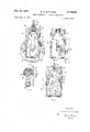
- FIG. 1 is a cross sectional View of one embodiment 3,716,321 Patented Feb. 13, 1973 ICC of the invention, the piston disposed at the terminal portion of its compression stroke.
- FIG. 2 is an end view of the compressor of FIG. 1 partially in section, valve means removed.
- FIG. 3 is a cross-section of the chamber and piston, the piston disposed approximately halfway through the intake stroke.
- FIG. 4 is identical to FIG. 1, the piston disposed halfway through the compression stroke.
- FIG. 5 is a section through the piston of FIG. 1.
- FIG. 6 is a comparative cross-section of the head portion of the piston showing two embodiments of ring configurations, and of spring retaining devices.
- FIG. 7 is a cross-section along lines 7 7 of FIG. 6.
- FIGS. 8, 9 and l0 are representative explanatory drawings of the ring in its various disposed positions during piston cycling with the circumscribing margin indicated as a dash line.
- FIG. ll being identical to FIG. 4 but disclosing a coating within the compression chamber.
- a compressor 20 includes an outer metal housing 21 with appropriate cooling fins 22 and cylindrical compression chamber 23.
- the compression chamber 23 has a cupola like cylinder head 24 of preferably spherical configuration, with apex (to create a void), the diameter of which is fractionally larger than the corresponding diameter of an upper crown member 33 to be later described.
- a valve means 25 including a small orifice 26 communicates the apex of the cylinder head 24 to a nipple 27 mounted on the housing 21 for subsequent communication to a reservoir (not shown).
- a ball 28 Disposed between the nipple 27 and the orifice 26, to provide sealing of the orifice, is a ball 28 biased by a spring means 29.
- a piston 31 includes a head portion 32 of truncated spherical shape having an upper crown member 33 of arcuate profile and a lower truncated skirt portion 34 with upper and lower surfaces 15 and 30, and a convex perimeter 35.
- the lower skirt portion 34 is rigidly connected to one end of a rigid piston rod 36 while the other end of the rod 36 has a protuberance 37 thereon with orifice 38.
- the orifice 38 accommodates a bearing bushing 39 of suitable type for connection to the throw arm 41 of a powershaft 42.
- the powershaft 42 is connected to an appropriate prime mover 45 such as an electric motor.
- the convex perimeter 35 preferably is a circumscribing ring 43 which is mounted on the skirt portion 34 by appropriate means to be described later.
- the skirt portion 34 is preferably dish shaped accommodating the upper and lower surfaces 15 and 30.
- Channels 47 communicate through the skirt portion to provide a passage for fluid from its lower surface 30 to its upper surface 15 for reasons which will become apparent.
- the upper crown member 33 biasly engages the upper surface 15 to sealingly close the channels 47 but is adapted to disassociate from the upper surface 15 during the intake stroke of the piston 31 to thereby openly expose the channels 47 such that fluid can pass through the channels from the lower portion 44 of the compression chamber 23 to the upper portion 46 thereof as more particularly illustrated in FIG. 4.
- a porous plate or screen 50 is provided across the lower extremely of the lower portion of the compression chamber 23. Filtering of the fluid entering the lower portion 44 from the elements is enhanced by the use of a gauze 65 or other suitable filtering media.
- the biasing of the upper crown member 33 to the upper surface 15 may be accommodated by (referring to the left side of FIG. 6) a flat head screw 48 with underlying spring means 49.
- the skirt portion 34 is constructed such that it has a stem 51 projecting from the upper surface coincident with the axis of the piston 31.
- the spring means 49 is mounted about the stem 51 and washers 52 are placed over the spring means 49.
- the stem 51 is then peened down in the usual manner to form a rivet type retaining lip 53. (See right hand of FIG. 6).
- the operation of the compressor is as follows:
- the powershaft 42 rotates clockwise and causes the throw arm 41 to move the piston 31 up and down within the compression chamber 23, in the following sequence.
- the piston 31 is disposed within the chamber at the terminal portion of the cornpression stroke (dead stop position).
- the powershaft 42 rotates 90 degrees (FIG. 4) the piston 31 is caused to be pulled downward in the chamber 23 while also being tilted to the left as shown.
- Such tilting results because of the fact that the piston 31 is rigid, that is there is no wrist pin between the head portion 34 and the rod portion 36.
- the titling is further accommodated by the convex perimeter 35 which describes the locus of the surface of a spheroid whose diameter is equal to that of the compression chamber 23.
- the width of the convex perimeter 35 more correctly the length of the chord 54 which subtends the convex perimeter, is such that the degree of tilt is accommodated.
- the circumscribing margin of contact 56 between the convex perimeter 35 and the walls of the compression chamber 23 always defines itself on the surface of the convex perimeter 35.
- valve means 25 stops shut the orifice 26 and a vacuum exists in the upper portion 46 (that part of the compression chamber between the apex and the piston head 32).
- a vacuum exists in the upper portion 46 (that part of the compression chamber between the apex and the piston head 32).
- fluid in the lower portion 44 of the compression chamber 23 is drawn through the channels 47, into the upper portion 46 as shown.
- the crown member 33 disassociates itself from the skirt portion 34 to expose the channels 47, and to thereby permit the fluid to flow.
- the ring 43 may be unitary, that is in the form of a solid annulus, in order to accommodate thermal expansion under severe operating conditions, the ring 43 preferably has a lap seam 55 consisting of two correspondingly dependent fingers 57 (FIG. 9) which form a juncture 58 in a plane coincident to the plane perpendicular to the axis of the ring.
- the fingers 57 expose at the extremities thereof an aperturel 59 to accommodate the expansion and contraction of the ring 43 as a result of thermal change.
- the fingers 57 may be juxtaposed one to another so that the juncture 58 is for all practical purposes a seal and yet permit a reasonable size aperture 59.
- the ring 43 is disposed on the lower skirt portion 34 such that the centre of the juncture 58 rests on the pivot axis 61 of the piston head 32.
- the juncture 58 may be described as being intersected (preferably bisecting the juncture 53) at right angles by the plane which intersects both the axis of the piston rod portion 36 and the axis 61 of rotation of the piston 31.
- the juncture 58 may be retained in the position such that the pivot axis 61 narrows it, -by an appropriate holding means such as a hold rod 62 disposed between the ring 43 and the lower skirt portion 34.
- the disposition of the juncture 58 in the manner described insures that no fluid passes between the convex surface 35 and the walls of the cylinder 23, during any portion of the operating cycle of the compressor, especially during the vital compression stroke.
- the composition of the ring 43 should be soft and pliable but wear resistant. It has been found that a suitable material includes tetrafluoride composition such as Teflon, Teflon bronze, glasslilled Teflon and the like. Nevertheless the actual composition for any particular compressor depends upon the wall characteristics of the chamber 23.
- Teflon and Teflon bronze have been found to be satisfactory where the housing 21 is composed of cast steel and the walls of the chamber 23 have been honed, for example, 16 to 24 microns.
- the housing is made of cast zinc, it has been found that by standard copper plating techniques the walls of the compression chamber 23 can be plated with copper, and thereafter plated with a thin coating (0.000 to 0.0001") of nickel which provides a porous and visually dull surface to the walls of the compression chamber 23.
- a ring material of Teflon bronze or for high durability of the ring material, glass-filled Teflon is used, excellent wear resistant properties for the ring are achieved. Further it has been found that glass-filled Teflon is an extremely good material for the upper crown member 33.
- the ring 43 and skirt portion 34 may have different profiles.
- the ring has an interior profile of that of a groove or channel 71 while the skirt portion has a radially extending tongue 72 which fits into the groove 71.
- the skirt portion may have a radially extending groove 73 while the ring may have a flat profile 76 as shown.
- the skirt portion 34 has radially extending arms 77 which accommodate the ring 43, the tips of which are arcuate and somewhat recessed from the loci traced yby the surface of a spheroid the convex perimeter 35 is coincident.
- the compressor disclosed can pump air to a pressure in the neigbourhood of p.s.i. providing of course a sutilciently powerful prime mover 45 is attaced to the powershaft 42.
- larger bore compression chambers 23 for example 2" bores, it has been found that the self resilience of the ring 43 is insufficient to constrain the ring 3 against the walls of the compression chamber 23 to ensure good compression.
- an encircling spring member (not shown) adapted to urge the ring 43 radially outward against the walls of the chamber 23.
- the housing of FIG. 4 is satisfactory, it has been found that in order to accommodate mass production in the casting of the housing 21, the housing preferably is provided with a threaded channel 78 communicating with the apex of the compression chamber 23 as shown in FIG. 2.
- valve means 25 is threaded.
- the valve means 25 has its face 79 shaped into cupola to accommodate the upper part of the upper crown member 33 as shown in FIGS. 1, 2, 3 and 4.
- the compression chamber 23 has on the interior surface thereof a thin coating 60 of wear resistant material.
- the wear resistant material is a zinc compound.
- the zinc compound is a Zinc anodised coating or what is commonly called anodic film on zinc from electroytes containing one or more anions from the group of glass forming elements-B, Al, Si, or P, plus one or more anions from a group of elements such as Cr, Mn, V or Mo.
- More particularly sodium silicate-chromate (SSC), sodium silicate-chromate-vanadate (SSCV) and sodium silicatechromate-manganate (SSCMn) electrolytes for anodising zinc have been used.
- such coating having a range of thickness of 0.0075 to 0.0015 inch, particularly 0.0040 inch provides a satisfactory anodic zinc protective coating, 60, on the walls of the zinc alloy, or coated zinc walls of the compression chamber 23 and as a result improves the wear resistance of the chamber 26 particularly from corrosion, erosion, abrasion and also reduces the friction of the tetratluoride composition circumscribing ring 43 on the walls of the compression chamber 23.
- a fluid compressor including a power shaft, a compression chamber with a circular cross section having cylindrical walls and a cupola shaped cylinder head with apex to create a void, a channel including a valve means therein communicating through said cupola shaped cylinder head with said chamber such that uid within the compression chamber may be ejected therethrough, and
- a piston said piston comprising an essentially hemispheri cal shaped head portion with an upper arcuate crown member and a lower truncated skirt portion which corresponds to a diametrically symmetrical slice'from a sphere with a diameter corresponding to the diameter of the great circle of the skirt portion to dispose a convex perimeter between upper and lower surfaces; a rod portion rigidly connected to said skirt portion, said skirt portion having a channel therethrough communicating the upper and lower surfaces thereof, the diameter of the great circle of the skirt portion corresponding to that of the compression chamber such that a circumscribing margin about the convex perimeter is a circle adapted to frictionally engage the walls of the chamber during reciprocating oscillations of the piston, a biasing means for biasingly engaging the upper crown member with the upper surface of the lower truncated skirt portion to mate said upper crown member and said truncated skirt portion but adapted to disassociate from the skirt portion and to expose said channel during intake strokes of said piston, said crown member having
- the convex perimeter consists of an annular ring having a lap seam for thermal expansion and contraction thereof, said lap seam including two juxtaposed fingers of the ring, establishing a juncture seal between the fingers, said juncture disposed in a plane coincident to a plane perpendicular to the axis of the piston, while the extremities of the fingers expose an aperture to accommodate linear expansion of the ring, said ring held by a holding means, to retain the juncture of the lap seam such that it is intersected at right angles by the plane which intersects both the axis of the piston rod portion and the axis of rotation of the piston.
- the compressor of claim 5 wherein the ring consists of a tetrauoride composition selected from the class consisting of polytetralluoroethylene, polytetra'uoroethylene-bronze and glass-filled polytetrauoroethylene.
Landscapes
- Engineering & Computer Science (AREA)
- General Engineering & Computer Science (AREA)
- Mechanical Engineering (AREA)
- Chemical & Material Sciences (AREA)
- Combustion & Propulsion (AREA)
- Compressor (AREA)
- Compressors, Vaccum Pumps And Other Relevant Systems (AREA)
Applications Claiming Priority (1)
| Application Number | Priority Date | Filing Date | Title |
|---|---|---|---|
| CA77033 | 1970-03-09 |
Publications (1)
| Publication Number | Publication Date |
|---|---|
| US3716310A true US3716310A (en) | 1973-02-13 |
Family
ID=4086462
Family Applications (1)
| Application Number | Title | Priority Date | Filing Date |
|---|---|---|---|
| US00107932A Expired - Lifetime US3716310A (en) | 1970-03-09 | 1971-01-20 | Direct drive ball piston compressor |
Country Status (5)
| Country | Link |
|---|---|
| US (1) | US3716310A (enExample) |
| CA (1) | CA916112A (enExample) |
| DE (2) | DE2109678A1 (enExample) |
| FR (1) | FR2084391A5 (enExample) |
| GB (1) | GB1343733A (enExample) |
Cited By (41)
| Publication number | Priority date | Publication date | Assignee | Title |
|---|---|---|---|---|
| US3913458A (en) * | 1973-03-15 | 1975-10-21 | Guy Foures | Respirator actuating mechanism |
| US3961868A (en) * | 1974-02-21 | 1976-06-08 | Thomas Industries, Inc. | Air compressor |
| US4121498A (en) * | 1977-02-03 | 1978-10-24 | Moog Inc. | Pivotal positioning servoactuator |
| US4246833A (en) * | 1978-12-29 | 1981-01-27 | The United States Of America As Represented By The Secretary Of The Navy | High pressure spherical piston |
| US4484511A (en) * | 1982-11-23 | 1984-11-27 | Centrifugal Piston Expanders, Inc. | Piston |
| US4507868A (en) * | 1982-08-30 | 1985-04-02 | The Warner & Swasey Company | Coordinate measuring machine with a self aligning pneumatic counterbalance |
| GB2156481A (en) * | 1984-03-30 | 1985-10-09 | Kugelfischer G Schaefer & Co | Rocking piston structure for hydraulic system |
| US4662207A (en) * | 1984-12-20 | 1987-05-05 | Liras Pty. Limited | Hydraulically operated metal working tool |
| US4765292A (en) * | 1985-08-19 | 1988-08-23 | Morgado Ralph G | Self-sealing piston apparatus |
| US4829954A (en) * | 1985-08-19 | 1989-05-16 | Morgado Ralph G | Method of forming self-sealing piston |
| US4979878A (en) * | 1989-03-03 | 1990-12-25 | James L. Short | Relieved piston valve for fluid motor and fluid pump |
| US5011382A (en) * | 1989-01-26 | 1991-04-30 | Thompson George A | Reciprocating piston pump |
| US5282412A (en) * | 1992-06-30 | 1994-02-01 | General Motors Corporation | Piston ring subassembly, angulating piston assembly and method of making same |
| US5305916A (en) * | 1991-12-09 | 1994-04-26 | Kabushiki Kaisha San-Ai | Drip free, volume-adjustable, automatic liquid dispenser |
| US5816787A (en) * | 1996-04-24 | 1998-10-06 | Brinkerhoff; Robert B. | Motion conversion rotator apparatus and method |
| US5836235A (en) * | 1993-09-15 | 1998-11-17 | Fahrzeugtechnik Ebern Gmbh | Piston for hydraulic actuating cylinders |
| NL1019811C2 (nl) * | 2002-01-22 | 2003-07-23 | Hendrik Van Veen | Bolvormige zuiger met gefixeerde drijfstang. |
| US6626079B1 (en) | 2002-03-28 | 2003-09-30 | Rehco, Llc | Pneumatic motor |
| US20040154913A1 (en) * | 2001-03-12 | 2004-08-12 | Lah Ruben F. | Valve system and method for unheading a coke drum |
| US20050092592A1 (en) * | 2002-09-05 | 2005-05-05 | Lah Ruben F. | Systems and methods for deheading a coke drum |
| US20060081456A1 (en) * | 2004-04-22 | 2006-04-20 | Lah Ruben F | Remotely controlled decoking tool used in coke cutting operations |
| US20070034496A1 (en) * | 2001-03-12 | 2007-02-15 | Lah Ruben F | Delayed coker isolation valve systems |
| US20070215518A1 (en) * | 2004-04-22 | 2007-09-20 | Lah Ruben F | Systems and Methods for Remotely Determining and Changing Cutting Modes During Decoking |
| US20070251576A1 (en) * | 2006-03-09 | 2007-11-01 | Lah Ruben F | Valve Body and Condensate Holding Tank Flushing Systems and Methods |
| US20090060758A1 (en) * | 2004-06-30 | 2009-03-05 | S.A.I. Societa' Apparecchiature Idrauliche Spa | Fluid machine with radial cylinders |
| US7530574B2 (en) | 2003-04-11 | 2009-05-12 | Curtiss-Wright Flow Control Corporation | Dynamic flange seal and sealing system |
| US20090183980A1 (en) * | 2008-01-23 | 2009-07-23 | Lah Ruben F | Coke Drum Skirt |
| US20090200152A1 (en) * | 2004-04-22 | 2009-08-13 | Lah Ruben F | Remotely Controlled Decoking Tool Used in Coke Cutting Operations |
| US20090214394A1 (en) * | 2003-02-21 | 2009-08-27 | Lah Ruben F | Center feed system |
| US20090236212A1 (en) * | 2008-01-23 | 2009-09-24 | Lah Ruben F | Linked coke drum support |
| US7632381B2 (en) | 2001-03-12 | 2009-12-15 | Curtiss-Wright Flow Control Corporation | Systems for providing continuous containment of delayed coker unit operations |
| US20100226804A1 (en) * | 2009-03-05 | 2010-09-09 | Denso Corporation | Pump |
| US7819009B2 (en) | 2006-02-28 | 2010-10-26 | Frederic Borah | Vibration Monitoring System |
| US8123197B2 (en) | 2001-03-12 | 2012-02-28 | Curtiss-Wright Flow Control Corporation | Ethylene production isolation valve systems |
| US8459608B2 (en) | 2009-07-31 | 2013-06-11 | Curtiss-Wright Flow Control Corporation | Seat and valve systems for use in delayed coker system |
| US8545680B2 (en) | 2009-02-11 | 2013-10-01 | Curtiss-Wright Flow Control Corporation | Center feed system |
| US8679299B2 (en) | 2001-03-12 | 2014-03-25 | Curtiss-Wright Flow Control Corporation | Coke drum bottom de-heading system |
| US8851451B2 (en) | 2009-03-23 | 2014-10-07 | Curtiss-Wright Flow Control Corporation | Non-rising electric actuated valve operator |
| US9291056B2 (en) | 2010-08-30 | 2016-03-22 | Lawrence Livermore National Security, Llc | Harmonic uniflow engine |
| US20220106950A1 (en) * | 2019-10-01 | 2022-04-07 | Hitachi Industrial Equipment Systems Co., Ltd. | Compressor |
| US20250188921A1 (en) * | 2022-03-15 | 2025-06-12 | Hitachi Industrial Equipment Systems Co., Ltd. | Compressor |
Families Citing this family (9)
| Publication number | Priority date | Publication date | Assignee | Title |
|---|---|---|---|---|
| FR2270440A1 (en) * | 1974-05-06 | 1975-12-05 | Searle Russell | Swash-plate engine with two pistons per cylinder - have sealing surfaces piston ring forming part of sphere |
| DE3008709A1 (de) * | 1980-03-07 | 1981-09-24 | Fichtel & Sachs Ag, 8720 Schweinfurt | Kolben mit einem kolbenring |
| DD155856A3 (de) * | 1980-06-16 | 1982-07-14 | Eberhard Guenther | Pendelkolben ohne kolbenringe |
| DE3114286A1 (de) * | 1981-04-09 | 1982-11-04 | Skf Kugellagerfabriken Gmbh, 8720 Schweinfurt | Kugelkolben fuer verdichter oder dgl. |
| DE3233853A1 (de) * | 1982-09-11 | 1984-03-15 | Erich 7812 Bad Krozingen Becker | Pumpe mit kolben und gleitdichtung |
| DE3616968A1 (de) * | 1986-05-20 | 1987-11-26 | Bosch Gmbh Robert | Taumelkolben-kompressor |
| FR2744177B1 (fr) * | 1996-01-31 | 1998-04-10 | Perfect Circle Europ Sa | Ensemble bielle-piston pour cylindre de moteur ou de compresseur |
| DE20111182U1 (de) * | 2001-07-05 | 2002-08-08 | Alcan BDW GmbH & Co. KG, 85570 Markt Schwaben | Federelement für einen Kolben |
| DE102008045580B3 (de) * | 2008-01-10 | 2009-05-07 | Manfred Wanzke | Pleuelkolbenkompressor |
-
1970
- 1970-03-09 CA CA916112A patent/CA916112A/en not_active Expired
-
1971
- 1971-01-20 US US00107932A patent/US3716310A/en not_active Expired - Lifetime
- 1971-03-01 DE DE19712109678 patent/DE2109678A1/de active Pending
- 1971-03-01 DE DE19717107614U patent/DE7107614U/de not_active Expired
- 1971-03-09 FR FR7108161A patent/FR2084391A5/fr not_active Expired
- 1971-04-19 GB GB2459271*A patent/GB1343733A/en not_active Expired
Cited By (64)
| Publication number | Priority date | Publication date | Assignee | Title |
|---|---|---|---|---|
| US3913458A (en) * | 1973-03-15 | 1975-10-21 | Guy Foures | Respirator actuating mechanism |
| US3961868A (en) * | 1974-02-21 | 1976-06-08 | Thomas Industries, Inc. | Air compressor |
| US4121498A (en) * | 1977-02-03 | 1978-10-24 | Moog Inc. | Pivotal positioning servoactuator |
| US4246833A (en) * | 1978-12-29 | 1981-01-27 | The United States Of America As Represented By The Secretary Of The Navy | High pressure spherical piston |
| US4507868A (en) * | 1982-08-30 | 1985-04-02 | The Warner & Swasey Company | Coordinate measuring machine with a self aligning pneumatic counterbalance |
| US4484511A (en) * | 1982-11-23 | 1984-11-27 | Centrifugal Piston Expanders, Inc. | Piston |
| GB2156481A (en) * | 1984-03-30 | 1985-10-09 | Kugelfischer G Schaefer & Co | Rocking piston structure for hydraulic system |
| US4662207A (en) * | 1984-12-20 | 1987-05-05 | Liras Pty. Limited | Hydraulically operated metal working tool |
| US4765292A (en) * | 1985-08-19 | 1988-08-23 | Morgado Ralph G | Self-sealing piston apparatus |
| US4829954A (en) * | 1985-08-19 | 1989-05-16 | Morgado Ralph G | Method of forming self-sealing piston |
| US5011382A (en) * | 1989-01-26 | 1991-04-30 | Thompson George A | Reciprocating piston pump |
| US4979878A (en) * | 1989-03-03 | 1990-12-25 | James L. Short | Relieved piston valve for fluid motor and fluid pump |
| US5305916A (en) * | 1991-12-09 | 1994-04-26 | Kabushiki Kaisha San-Ai | Drip free, volume-adjustable, automatic liquid dispenser |
| US5282412A (en) * | 1992-06-30 | 1994-02-01 | General Motors Corporation | Piston ring subassembly, angulating piston assembly and method of making same |
| US5836235A (en) * | 1993-09-15 | 1998-11-17 | Fahrzeugtechnik Ebern Gmbh | Piston for hydraulic actuating cylinders |
| US5816787A (en) * | 1996-04-24 | 1998-10-06 | Brinkerhoff; Robert B. | Motion conversion rotator apparatus and method |
| US8679299B2 (en) | 2001-03-12 | 2014-03-25 | Curtiss-Wright Flow Control Corporation | Coke drum bottom de-heading system |
| US20040154913A1 (en) * | 2001-03-12 | 2004-08-12 | Lah Ruben F. | Valve system and method for unheading a coke drum |
| US8282074B2 (en) | 2001-03-12 | 2012-10-09 | Curtiss-Wright Flow Control Corporation | Delayed coker isolation valve systems |
| US8512525B2 (en) | 2001-03-12 | 2013-08-20 | Curtiss-Wright Flow Control Corporation | Valve system and method for unheading a coke drum |
| US20070034496A1 (en) * | 2001-03-12 | 2007-02-15 | Lah Ruben F | Delayed coker isolation valve systems |
| US20070084714A1 (en) * | 2001-03-12 | 2007-04-19 | Lah Ruben F | Valve system and method for unheading a coke drum |
| US7632381B2 (en) | 2001-03-12 | 2009-12-15 | Curtiss-Wright Flow Control Corporation | Systems for providing continuous containment of delayed coker unit operations |
| US7578907B2 (en) | 2001-03-12 | 2009-08-25 | Curtiss-Wright Flow Control Corporation | Valve system for unheading a coke drum |
| US8123197B2 (en) | 2001-03-12 | 2012-02-28 | Curtiss-Wright Flow Control Corporation | Ethylene production isolation valve systems |
| NL1019811C2 (nl) * | 2002-01-22 | 2003-07-23 | Hendrik Van Veen | Bolvormige zuiger met gefixeerde drijfstang. |
| US20040060429A1 (en) * | 2002-03-28 | 2004-04-01 | Jeffrey Rehkemper | Pneumatic motor |
| US6862973B2 (en) | 2002-03-28 | 2005-03-08 | Rehco, Llc | Pneumatic motor |
| US6626079B1 (en) | 2002-03-28 | 2003-09-30 | Rehco, Llc | Pneumatic motor |
| US20060175188A1 (en) * | 2002-09-05 | 2006-08-10 | Lah Ruben F | Coke drum bottom throttling valve and system |
| US7399384B2 (en) | 2002-09-05 | 2008-07-15 | Curtiss-Wright Flow Control Corporation | Coke drum bottom throttling valve and system |
| US7459063B2 (en) | 2002-09-05 | 2008-12-02 | Curtiss-Wright Flow Control Corporation | Systems and methods for deheading a coke drum |
| US20050092592A1 (en) * | 2002-09-05 | 2005-05-05 | Lah Ruben F. | Systems and methods for deheading a coke drum |
| US20090214394A1 (en) * | 2003-02-21 | 2009-08-27 | Lah Ruben F | Center feed system |
| US8702911B2 (en) | 2003-02-21 | 2014-04-22 | Curtiss-Wright Flow Control Corporation | Center feed system |
| US7682490B2 (en) | 2003-04-11 | 2010-03-23 | Curtiss-Wright Flow Control Corporation | Dynamic flange seal and sealing system |
| US7530574B2 (en) | 2003-04-11 | 2009-05-12 | Curtiss-Wright Flow Control Corporation | Dynamic flange seal and sealing system |
| US20090200152A1 (en) * | 2004-04-22 | 2009-08-13 | Lah Ruben F | Remotely Controlled Decoking Tool Used in Coke Cutting Operations |
| US7473337B2 (en) | 2004-04-22 | 2009-01-06 | Curtiss-Wright Flow Control Corporation | Remotely controlled decoking tool used in coke cutting operations |
| US8679298B2 (en) | 2004-04-22 | 2014-03-25 | Curtiss-Wright Flow Control Corporation | Remotely controlled decoking tool used in coke cutting operations |
| US20070215518A1 (en) * | 2004-04-22 | 2007-09-20 | Lah Ruben F | Systems and Methods for Remotely Determining and Changing Cutting Modes During Decoking |
| US20060081456A1 (en) * | 2004-04-22 | 2006-04-20 | Lah Ruben F | Remotely controlled decoking tool used in coke cutting operations |
| US7820014B2 (en) | 2004-04-22 | 2010-10-26 | Lah Ruben F | Systems and methods for remotely determining and changing cutting modes during decoking |
| US8197644B2 (en) | 2004-04-22 | 2012-06-12 | Curtiss-Wright Flow Control Corporation | Remotely controlled decoking tool used in coke cutting operations |
| US20090060758A1 (en) * | 2004-06-30 | 2009-03-05 | S.A.I. Societa' Apparecchiature Idrauliche Spa | Fluid machine with radial cylinders |
| US8382449B2 (en) * | 2004-06-30 | 2013-02-26 | S.A.I. Societa' Apparecchiature Idrauliche Spa | Fluid machine with radial cylinders |
| US7819009B2 (en) | 2006-02-28 | 2010-10-26 | Frederic Borah | Vibration Monitoring System |
| US7931044B2 (en) | 2006-03-09 | 2011-04-26 | Curtiss-Wright Flow Control Corporation | Valve body and condensate holding tank flushing systems and methods |
| US20070251576A1 (en) * | 2006-03-09 | 2007-11-01 | Lah Ruben F | Valve Body and Condensate Holding Tank Flushing Systems and Methods |
| US7871500B2 (en) | 2008-01-23 | 2011-01-18 | Curtiss-Wright Flow Control Corporation | Coke drum skirt |
| US8440057B2 (en) | 2008-01-23 | 2013-05-14 | Curtiss-Wright Flow Control Corporation | Linked coke drum support |
| US20090183980A1 (en) * | 2008-01-23 | 2009-07-23 | Lah Ruben F | Coke Drum Skirt |
| US20090236212A1 (en) * | 2008-01-23 | 2009-09-24 | Lah Ruben F | Linked coke drum support |
| US8545680B2 (en) | 2009-02-11 | 2013-10-01 | Curtiss-Wright Flow Control Corporation | Center feed system |
| US20100226804A1 (en) * | 2009-03-05 | 2010-09-09 | Denso Corporation | Pump |
| US8348644B2 (en) * | 2009-03-05 | 2013-01-08 | Denso Corporation | High pressure fuel injector supply pump |
| US8851451B2 (en) | 2009-03-23 | 2014-10-07 | Curtiss-Wright Flow Control Corporation | Non-rising electric actuated valve operator |
| US8459608B2 (en) | 2009-07-31 | 2013-06-11 | Curtiss-Wright Flow Control Corporation | Seat and valve systems for use in delayed coker system |
| US9291056B2 (en) | 2010-08-30 | 2016-03-22 | Lawrence Livermore National Security, Llc | Harmonic uniflow engine |
| US20220106950A1 (en) * | 2019-10-01 | 2022-04-07 | Hitachi Industrial Equipment Systems Co., Ltd. | Compressor |
| EP4039977A4 (en) * | 2019-10-01 | 2023-10-04 | Hitachi Industrial Equipment Systems Co., Ltd. | COMPRESSOR |
| US12116996B2 (en) * | 2019-10-01 | 2024-10-15 | Hitachi Industrial Equipment Systems Co., Ltd. | Compressor with piston ring arrangement on piston |
| US20250188921A1 (en) * | 2022-03-15 | 2025-06-12 | Hitachi Industrial Equipment Systems Co., Ltd. | Compressor |
| US12529375B2 (en) * | 2022-03-15 | 2026-01-20 | Hitachi Industrial Equipment Systems Co. Ltd. | Compressor |
Also Published As
| Publication number | Publication date |
|---|---|
| FR2084391A5 (enExample) | 1971-12-17 |
| CA916112A (en) | 1972-12-05 |
| DE2109678A1 (de) | 1971-09-30 |
| DE7107614U (de) | 1975-09-04 |
| GB1343733A (en) | 1974-01-16 |
Similar Documents
| Publication | Publication Date | Title |
|---|---|---|
| US3716310A (en) | Direct drive ball piston compressor | |
| US3953154A (en) | Pressure control and unloader valve | |
| KR0161309B1 (ko) | 냉동압축기의 배출밸브장치 및 밀폐식 냉동압축기 | |
| US4697992A (en) | Piston ring for a piston in a refrigerant compressor | |
| US5231917A (en) | Wobble piston | |
| US4420986A (en) | Sliding shoe for a rotatable swash-plate type refrigerant gas compressor | |
| KR19980042651A (ko) | 사판식 압축기 | |
| US5064359A (en) | Annular support for a seal for a tilt piston | |
| US5775886A (en) | Gas compressor with reciprocating piston with valve sheath | |
| US6422129B1 (en) | Swash plate type refrigerant compressor | |
| JPH1089253A (ja) | ワッブル型ピストン・シリンダ装置 | |
| US4984812A (en) | Oil seal assembly | |
| US4644850A (en) | Fluid machine | |
| US20030096134A1 (en) | Sliding member for compressor | |
| JPH10153170A (ja) | 斜板式圧縮機のピストン | |
| US20040161352A1 (en) | Shaped valve seats in displacement compressors | |
| DE3114286C2 (enExample) | ||
| US20020046646A1 (en) | Compressors | |
| US4209285A (en) | Unitary pump packing | |
| CN2345729Y (zh) | 一种往复式隔膜泵 | |
| JPH0215079Y2 (enExample) | ||
| CN2045029U (zh) | 微型往复式球形活塞两用机 | |
| US4208845A (en) | Method for grinding piston rings | |
| GB1465922A (en) | Pumps or compressors | |
| KR820000997B1 (ko) | 피스톤 및 피스톤링 조립체 |
Legal Events
| Date | Code | Title | Description |
|---|---|---|---|
| AS | Assignment |
Owner name: WEBSTER MFG. (LONDON) LIMITED, P.O. BOX 4580, 1161 Free format text: ASSIGNMENT OF ASSIGNORS INTEREST.;ASSIGNOR:GUNWEB LIMITED;REEL/FRAME:004197/0806 Effective date: 19831110 |