US3709640A - Means for the production of moulded components from chemical components whch react quickly with one another - Google Patents
Means for the production of moulded components from chemical components whch react quickly with one another Download PDFInfo
- Publication number
- US3709640A US3709640A US00072298A US3709640DA US3709640A US 3709640 A US3709640 A US 3709640A US 00072298 A US00072298 A US 00072298A US 3709640D A US3709640D A US 3709640DA US 3709640 A US3709640 A US 3709640A
- Authority
- US
- United States
- Prior art keywords
- components
- sprue
- mixing chamber
- mixture
- another
- Prior art date
- Legal status (The legal status is an assumption and is not a legal conclusion. Google has not performed a legal analysis and makes no representation as to the accuracy of the status listed.)
- Expired - Lifetime
Links
- 239000000126 substance Substances 0.000 title abstract description 7
- 238000004519 manufacturing process Methods 0.000 title description 6
- 239000000203 mixture Substances 0.000 claims description 19
- 238000002156 mixing Methods 0.000 abstract description 55
- 238000000465 moulding Methods 0.000 abstract description 26
- 238000000926 separation method Methods 0.000 abstract description 19
- 239000000463 material Substances 0.000 description 4
- 238000011010 flushing procedure Methods 0.000 description 3
- 239000003795 chemical substances by application Substances 0.000 description 2
- 230000007547 defect Effects 0.000 description 2
- 239000002245 particle Substances 0.000 description 2
- 229920002635 polyurethane Polymers 0.000 description 2
- 239000004814 polyurethane Substances 0.000 description 2
- 239000007787 solid Substances 0.000 description 2
- 239000002904 solvent Substances 0.000 description 2
- KNIUHBNRWZGIQQ-UHFFFAOYSA-N 7-diethoxyphosphinothioyloxy-4-methylchromen-2-one Chemical compound CC1=CC(=O)OC2=CC(OP(=S)(OCC)OCC)=CC=C21 KNIUHBNRWZGIQQ-UHFFFAOYSA-N 0.000 description 1
- 238000007664 blowing Methods 0.000 description 1
- 238000005266 casting Methods 0.000 description 1
- 150000001768 cations Chemical class 0.000 description 1
- 238000004140 cleaning Methods 0.000 description 1
- 230000003749 cleanliness Effects 0.000 description 1
- 230000000295 complement effect Effects 0.000 description 1
- 229920001577 copolymer Polymers 0.000 description 1
- 230000000694 effects Effects 0.000 description 1
- 238000000605 extraction Methods 0.000 description 1
- 239000010419 fine particle Substances 0.000 description 1
- 238000005187 foaming Methods 0.000 description 1
- 239000007788 liquid Substances 0.000 description 1
- 238000000034 method Methods 0.000 description 1
- 229920000647 polyepoxide Polymers 0.000 description 1
- 239000011148 porous material Substances 0.000 description 1
- 229920006305 unsaturated polyester Polymers 0.000 description 1
- 239000002699 waste material Substances 0.000 description 1
Images
Classifications
-
- B—PERFORMING OPERATIONS; TRANSPORTING
- B29—WORKING OF PLASTICS; WORKING OF SUBSTANCES IN A PLASTIC STATE IN GENERAL
- B29C—SHAPING OR JOINING OF PLASTICS; SHAPING OF MATERIAL IN A PLASTIC STATE, NOT OTHERWISE PROVIDED FOR; AFTER-TREATMENT OF THE SHAPED PRODUCTS, e.g. REPAIRING
- B29C44/00—Shaping by internal pressure generated in the material, e.g. swelling or foaming ; Producing porous or cellular expanded plastics articles
- B29C44/34—Auxiliary operations
- B29C44/3442—Mixing, kneading or conveying the foamable material
-
- B—PERFORMING OPERATIONS; TRANSPORTING
- B29—WORKING OF PLASTICS; WORKING OF SUBSTANCES IN A PLASTIC STATE IN GENERAL
- B29B—PREPARATION OR PRETREATMENT OF THE MATERIAL TO BE SHAPED; MAKING GRANULES OR PREFORMS; RECOVERY OF PLASTICS OR OTHER CONSTITUENTS OF WASTE MATERIAL CONTAINING PLASTICS
- B29B7/00—Mixing; Kneading
- B29B7/74—Mixing; Kneading using other mixers or combinations of mixers, e.g. of dissimilar mixers ; Plant
- B29B7/7471—Mixers in which the mixing takes place at the inlet of a mould, e.g. mixing chambers situated in the mould opening
-
- B—PERFORMING OPERATIONS; TRANSPORTING
- B29—WORKING OF PLASTICS; WORKING OF SUBSTANCES IN A PLASTIC STATE IN GENERAL
- B29C—SHAPING OR JOINING OF PLASTICS; SHAPING OF MATERIAL IN A PLASTIC STATE, NOT OTHERWISE PROVIDED FOR; AFTER-TREATMENT OF THE SHAPED PRODUCTS, e.g. REPAIRING
- B29C33/00—Moulds or cores; Details thereof or accessories therefor
- B29C33/0061—Moulds or cores; Details thereof or accessories therefor characterised by the configuration of the material feeding channel
- B29C33/0072—Moulds or cores; Details thereof or accessories therefor characterised by the configuration of the material feeding channel with a configuration promoting turbulency, e.g. for after-mixing in the mould
-
- B—PERFORMING OPERATIONS; TRANSPORTING
- B29—WORKING OF PLASTICS; WORKING OF SUBSTANCES IN A PLASTIC STATE IN GENERAL
- B29C—SHAPING OR JOINING OF PLASTICS; SHAPING OF MATERIAL IN A PLASTIC STATE, NOT OTHERWISE PROVIDED FOR; AFTER-TREATMENT OF THE SHAPED PRODUCTS, e.g. REPAIRING
- B29C67/00—Shaping techniques not covered by groups B29C39/00 - B29C65/00, B29C70/00 or B29C73/00
- B29C67/24—Shaping techniques not covered by groups B29C39/00 - B29C65/00, B29C70/00 or B29C73/00 characterised by the choice of material
- B29C67/246—Moulding high reactive monomers or prepolymers, e.g. by reaction injection moulding [RIM], liquid injection moulding [LIM]
-
- Y—GENERAL TAGGING OF NEW TECHNOLOGICAL DEVELOPMENTS; GENERAL TAGGING OF CROSS-SECTIONAL TECHNOLOGIES SPANNING OVER SEVERAL SECTIONS OF THE IPC; TECHNICAL SUBJECTS COVERED BY FORMER USPC CROSS-REFERENCE ART COLLECTIONS [XRACs] AND DIGESTS
- Y10—TECHNICAL SUBJECTS COVERED BY FORMER USPC
- Y10S—TECHNICAL SUBJECTS COVERED BY FORMER USPC CROSS-REFERENCE ART COLLECTIONS [XRACs] AND DIGESTS
- Y10S366/00—Agitating
- Y10S366/604—Lather maker
-
- Y—GENERAL TAGGING OF NEW TECHNOLOGICAL DEVELOPMENTS; GENERAL TAGGING OF CROSS-SECTIONAL TECHNOLOGIES SPANNING OVER SEVERAL SECTIONS OF THE IPC; TECHNICAL SUBJECTS COVERED BY FORMER USPC CROSS-REFERENCE ART COLLECTIONS [XRACs] AND DIGESTS
- Y10—TECHNICAL SUBJECTS COVERED BY FORMER USPC
- Y10S—TECHNICAL SUBJECTS COVERED BY FORMER USPC CROSS-REFERENCE ART COLLECTIONS [XRACs] AND DIGESTS
- Y10S521/00—Synthetic resins or natural rubbers -- part of the class 520 series
- Y10S521/917—Specialized mixing apparatus utilized in cell forming process
Definitions
- the present invention is concerned with an apparatus for the manufacture of solid or foamed molded components from chemical components which react quickly with one another. It is particularly concerned with an apparatus in which materials based on polyurethanes, unsaturated polyesters, epoxide resins, ecaprolactams and their copolymers may be reacted, a mixing chamber being connected to the interior of a molding tool.
- the mixing head is mounted on a fitting of the mold box in order to fill the interior of the mold.
- the mixture is introduced through a supply pipe into the interior of the mold from the mixing head.
- This arrangement has the disadvantage that, after completing the mixing operation, that is to say after filling the mold, the mixing chamber has to be flushed with a solvent or with compressed air. Such a procedure is costly, takes considerable time and does not ensure complete cleanliness of the mixing chamber. Moreover, unpleasant and undesired vapors are produced when using solvents, while, when blowing compressed air through the mixing head, the discharge of the fine particles of mixture atomized by the stream of compressed air is undesirable on account of harm caused to operating personnel.
- the present invention has as its object to provide an arrangement which avoids the use of flushing agents.
- the mixing head can be advantageously opened simultaneously with the opening of the molding tool, so that the mixing chamber is likewise exposed.
- the sprue rod which has simultaneously. been formed in the sprue and also the foamed mixture which has remained in the mixing chamber can be removed from the mold.
- the residue which remains in the mixing chamber is deliberately caused to complete foaming in the chamber.
- the sprue can be so shaped that it increases in size towards the internal chamber of the mold.
- the sprue can be made conical or trumpet-shaped and can be employed generally for molding tools. The purpose of the widening of the sprue is that a sudden change in pressure at the time of injecting the mixture into the mold, such as occurs with a cylindrical sprue, is avoided. This sudden expansion of the foamable mixture causes the discharge of the gas dissolved in the mixture and leads to casting defects,
- the sprue is advantageously designed as an exchangeable fitting.
- the invention provides for the sprue to have a deflection and for a collecting pocket to be arranged on the outside of the deflection.
- This has the particular advantage that the first part of the mixture is collected in the collecting pocket and consequently does not pass into the interior of the mold, but is removed together with the sprue rod as waste on emptying the mold.
- the first part of the mixture usually does not represent a foamable mixture because the components have not been completely mixed owing to one of the components being introduced first on opening the inlet nozzles.
- the collecting pocket can, however, be used independently of the main feature of the invention.
- the mixing chamber is arranged directly in the molding tool.
- the mixing chamber must be intersected by the separation plane of the mold or the separation plane must be at a tangent to the mixing chamber, and in fact in such a way that each of the two molding tool parts forms a portion of the wall of the mixing chamber. It is only in this case that the mixing chamber is also open on opening the molding tool. It is immaterial in this respect whether the separation plane of the molding tool lies in the same geometrical plane as the separation plane of the sprue or of the mixing chamber.
- the expression separation plane is here to be understood as meaning the separation of the molding tool, the sprue and the mixing chamber into two parts, regardless of whether parts of this separation plane are staggered with respect to one another.
- part of the separation plane affecting the interior of the mold it is possible for that part of the separation plane affecting the interior of the mold to be arranged horizontally, while the part of the separation plane of the sprue and of the mixing chamber extend obliquely or perpendicularly thereto.
- the only limitation imposed on the disposition of the separation plane is that the molding too] must be able to be opened and the molded material to be removed.
- the mixing chamber is arranged directly in the molding tool, and the mixing chamber consists of a mixing head which is adapted to be mounted in a manner known per se on a fitting of the molding tool, and consists according to the invention of two housing components which can be connected to one another.
- the mixing head and molding tool can be separated from one another.
- the molding tool and mixing head are thus capable of being separately opened and closed.
- the connection of. the parts of the housing of the mixing head is advantageously efiected by a quick-closure device as known per se, for example by a tensioning screw or a tensioning band.
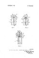
- FIG. 1 shows the arrangement with a mixing head arranged in a molding tool
- a molding tool 1 comprises mold box sections 2 and 3 which enclose an internal chamber 4 of the mold.
- the separation plane between the two mold box sections is indicated at 5.
- a mixing head 6 is moved -into the molding tool 1 in such a way that a mixing chamber 7 is intersected by the mold separation plane.
- An inlet nozzle 8 is arranged in the mold box section 2, while an inlet nozzle 9 for a second component is provided in the mold box section 3.
- a sprue 10 extends directly from the mixing chamber 7 to the internal chamber 4 of the mold. This sprue 10 widens out conically in order to avoid the emergence of gas dissolved in the mixture.
- a collecting pocket 11 is disposed alongside the sprue 10 longitudinally thereof.
- the pocket collects the first incompletely mixed portion of the liquid mixture.
- the conical part of the sprue 10 is constructed as a replaceable, two-part fitting 10a.
- the main portion of the foamable mixture reaches the interior 4 of the mold through the sprue 12. With this embodiment, the sprue 10 directly adjoins the mixing chamber 7.
- the molding tool 1 is provided with a fitting 13 which is shaped to complement a coacting part 14 of the mixing head 6.
- the separation plane of the mold is indicated at 5 and it is offset with respect to the separation plane 15 of the mixing head.
- the sprue is disposed partly in the molding tool 1 and partly in the mixing head 6.
- the mixing head 6 itself consists of two housing v sections 16 and 17, which are pressed one against the other in the closed position and thus close off the mixing chamber 7 from the exterior.
- the inlet nozzles for the components are indicated at 8 and 9.
- the two housing sections 16 and 17 are adapted to pivot on supporting arms 18 and 19 about a common shaft 20. This shaft is fixed on a sliding rod 21 by means of which the mixing head 6 can be moved towards or away from the molding tool 1.
- An apparatus for'manufacture of solid or foamed articles from chemical components which react quickly with one another, such as components for the production of polyurethane, comprisingz l a. a mould formed by a wall defining a mould cavity,
- said mould, wall being formed by'two separable parts defined by a separation plane extending through the mixing chamber and the sprue passageway, whereby following filling of the mould and reaction of the components forming the article, the mo ld parts can be separate? alon the separation p ane, permitting removal 0 the ar icle,
- the sprue passageway including a turning portion for deflection of the components in the sprue passageway, a collect: ing pocket communicating with the turning portion for receiving and entraping the first portion of the mixture of components passing through the sprue passageway.
- the sprue passageway including a turning portion for deflection of the components in the sprue passageway, a collecting pocket communicating with the turning portion for receiving and entraping the first portion of the mixture of components passing through the sprue passageway.
- the sprue passageway including a turning portion for deflection of the components in the sprue passageway, a collecting pocket communicating with the turning portion for receiving and entraping the first portion of the mixture of components passing through the sprue passageway.
Landscapes
- Engineering & Computer Science (AREA)
- Mechanical Engineering (AREA)
- Injection Moulding Of Plastics Or The Like (AREA)
- Moulds For Moulding Plastics Or The Like (AREA)
- Processing And Handling Of Plastics And Other Materials For Molding In General (AREA)
- Casting Or Compression Moulding Of Plastics Or The Like (AREA)
- Molding Of Porous Articles (AREA)
Applications Claiming Priority (1)
| Application Number | Priority Date | Filing Date | Title |
|---|---|---|---|
| DE1948999A DE1948999C3 (de) | 1969-09-27 | 1969-09-27 | Vorrichtung zum Herstellen von massiven oder geschäumten Formteilen aus schnell miteinander reagierenden chemischen Komponenten |
Publications (1)
| Publication Number | Publication Date |
|---|---|
| US3709640A true US3709640A (en) | 1973-01-09 |
Family
ID=5746745
Family Applications (1)
| Application Number | Title | Priority Date | Filing Date |
|---|---|---|---|
| US00072298A Expired - Lifetime US3709640A (en) | 1969-09-27 | 1970-09-15 | Means for the production of moulded components from chemical components whch react quickly with one another |
Country Status (7)
| Country | Link |
|---|---|
| US (1) | US3709640A (enExample) |
| JP (1) | JPS4830135B1 (enExample) |
| BE (1) | BE756664A (enExample) |
| CA (1) | CA943714A (enExample) |
| DE (1) | DE1948999C3 (enExample) |
| FR (1) | FR2063041B1 (enExample) |
| GB (1) | GB1318792A (enExample) |
Cited By (5)
| Publication number | Priority date | Publication date | Assignee | Title |
|---|---|---|---|---|
| US3847526A (en) * | 1971-03-16 | 1974-11-12 | Anker Werk Nuernberg Gmbh | Material mixing moulding apparatus for use with a mould to shape a plastics material |
| US3924989A (en) * | 1972-10-25 | 1975-12-09 | Bayer Ag | Machine for producing moldings from chemical components which react quickly with one another |
| US4097928A (en) * | 1973-09-14 | 1978-06-27 | Demag Kunststofftechnik Zweigniederlassung Der Demag Ag | Apparatus for feeding synthetic material to a mould |
| US4379105A (en) * | 1980-07-21 | 1983-04-05 | Mobay Chemical Corporation | Process for the production of elastic shaped articles |
| US4729863A (en) * | 1984-05-26 | 1988-03-08 | Bayer Aktiengesellschaft | Process and molding tool for the manufacture of molded parts having areas in the form of grids, grills or gratings, such as motor vehicle soft-faces, spoilers, bumpers from a fluid mass |
Families Citing this family (7)
| Publication number | Priority date | Publication date | Assignee | Title |
|---|---|---|---|---|
| DE2327269C3 (de) * | 1973-05-29 | 1981-04-09 | Krauss-Maffei AG, 8000 München | Vorrichtung zum Zuleiten eines insbesondere chemischreaktionsfähigen Kunststoffgemisches zu einer Form |
| DE2413357C2 (de) * | 1974-03-20 | 1983-11-17 | Bayer Ag, 5090 Leverkusen | Mischvorrichtung zum Herstellen von Mehrkomponenten-Kunststoffen |
| JPS52131233U (enExample) * | 1976-03-31 | 1977-10-05 | ||
| DE3216647A1 (de) * | 1982-05-04 | 1983-11-10 | Elastogran Maschinenbau GmbH, 2844 Lemförde | Mischvorrichtung fuer mehrkomponentenkunststoffe |
| DE3522377A1 (de) * | 1985-06-22 | 1987-01-02 | Bayer Ag | Verfahren und vorrichtung zum herstellen von formteilen aus einem massiven oder mikrozellularen kunststoff, insbesondere polyurethan bildenden, fliessfaehigen reaktionsgemisch aus mindestens zwei fliessfaehigen reaktionskomponenten |
| DE102006018812A1 (de) * | 2006-04-22 | 2007-10-25 | Krauss Maffei Gmbh | Mischvorrichtung für reaktive Kunststoffkomponenten und Verfahren zum Betrieb einer solchen Mischvorrichtung |
| AT518860B1 (de) | 2016-07-29 | 2018-02-15 | Engel Austria Gmbh | Verfahren zur Herstellung von Kunststoffbauteilen |
Citations (3)
| Publication number | Priority date | Publication date | Assignee | Title |
|---|---|---|---|---|
| US2994921A (en) * | 1961-08-08 | Molding device | ||
| US3278658A (en) * | 1963-12-05 | 1966-10-11 | Koppers Co Inc | Process and apparatus for making shaped cellular articles from expandable thermoplastic resins |
| US3551947A (en) * | 1968-09-03 | 1971-01-05 | Control Building Systems Inc | Apparatus for filling molds with polyurethane |
-
0
- BE BE756664D patent/BE756664A/xx unknown
-
1969
- 1969-09-27 DE DE1948999A patent/DE1948999C3/de not_active Expired
-
1970
- 1970-09-04 CA CA092,329A patent/CA943714A/en not_active Expired
- 1970-09-15 US US00072298A patent/US3709640A/en not_active Expired - Lifetime
- 1970-09-25 GB GB4572170A patent/GB1318792A/en not_active Expired
- 1970-09-25 FR FR707034899A patent/FR2063041B1/fr not_active Expired
- 1970-09-28 JP JP45084178A patent/JPS4830135B1/ja active Pending
Patent Citations (3)
| Publication number | Priority date | Publication date | Assignee | Title |
|---|---|---|---|---|
| US2994921A (en) * | 1961-08-08 | Molding device | ||
| US3278658A (en) * | 1963-12-05 | 1966-10-11 | Koppers Co Inc | Process and apparatus for making shaped cellular articles from expandable thermoplastic resins |
| US3551947A (en) * | 1968-09-03 | 1971-01-05 | Control Building Systems Inc | Apparatus for filling molds with polyurethane |
Cited By (5)
| Publication number | Priority date | Publication date | Assignee | Title |
|---|---|---|---|---|
| US3847526A (en) * | 1971-03-16 | 1974-11-12 | Anker Werk Nuernberg Gmbh | Material mixing moulding apparatus for use with a mould to shape a plastics material |
| US3924989A (en) * | 1972-10-25 | 1975-12-09 | Bayer Ag | Machine for producing moldings from chemical components which react quickly with one another |
| US4097928A (en) * | 1973-09-14 | 1978-06-27 | Demag Kunststofftechnik Zweigniederlassung Der Demag Ag | Apparatus for feeding synthetic material to a mould |
| US4379105A (en) * | 1980-07-21 | 1983-04-05 | Mobay Chemical Corporation | Process for the production of elastic shaped articles |
| US4729863A (en) * | 1984-05-26 | 1988-03-08 | Bayer Aktiengesellschaft | Process and molding tool for the manufacture of molded parts having areas in the form of grids, grills or gratings, such as motor vehicle soft-faces, spoilers, bumpers from a fluid mass |
Also Published As
| Publication number | Publication date |
|---|---|
| GB1318792A (en) | 1973-05-31 |
| CA943714A (en) | 1974-03-19 |
| DE1948999C3 (de) | 1975-10-16 |
| BE756664A (fr) | 1971-03-01 |
| FR2063041A1 (enExample) | 1971-07-02 |
| DE1948999A1 (de) | 1971-04-22 |
| FR2063041B1 (enExample) | 1974-07-12 |
| DE1948999B2 (enExample) | 1973-10-11 |
| JPS4830135B1 (enExample) | 1973-09-18 |
Similar Documents
| Publication | Publication Date | Title |
|---|---|---|
| US3709640A (en) | Means for the production of moulded components from chemical components whch react quickly with one another | |
| US5556039A (en) | Crushing machine apparatus and a method for cleaning the crushing machine apparatus | |
| US4275033A (en) | Apparatus for producing a reaction mixture containing fillers from at least two components which are capable of flowing | |
| US3970732A (en) | Method of molding rigid foamed polyurethane articles | |
| JP2007518590A (ja) | ゴム系及びシリコン系プラスチック材料を混合し押出処理するための機械、並びにその方法 | |
| CA1077215A (en) | Apparatus for the production of foam materials containing a filler material | |
| KR102332507B1 (ko) | 재생플라스틱 펠릿 제조장치 | |
| US3232709A (en) | Foam generating apparatus | |
| US4725215A (en) | Extruder with exchangeable filter for foamed plastic material | |
| US3917779A (en) | Introduction of reactants into moulds and article produced | |
| US3982870A (en) | Apparatus for producing molded foam articles without defects | |
| JPH03213B2 (enExample) | ||
| EP0451921B1 (en) | Mixing head for mixing of liquid chemically interreacting plastic components | |
| US3771963A (en) | Production of foams and homogeneous materials and apparatus therefor | |
| US3908966A (en) | Mixing apparatus | |
| KR100187536B1 (ko) | 전자부품의 수지밀봉 성형장치 | |
| JPS6089322A (ja) | 反応射出成形方法およびその装置 | |
| EP0084841A2 (en) | Method and apparatus for blowing cores etc. | |
| JPH0327008B2 (enExample) | ||
| US3794451A (en) | Introduction of reactants into moulds | |
| JP2676550B2 (ja) | 成形機用洗浄剤 | |
| JPS59227425A (ja) | 発泡射出成形法 | |
| US2792594A (en) | Universal molding machine | |
| JPH08118356A (ja) | 型成形用樹脂再生材の製造方法および製造装置 | |
| US4082251A (en) | Mixing head for a machine for producing multicomponent plastics |