EP0451921B1 - Mixing head for mixing of liquid chemically interreacting plastic components - Google Patents
Mixing head for mixing of liquid chemically interreacting plastic components Download PDFInfo
- Publication number
- EP0451921B1 EP0451921B1 EP91200827A EP91200827A EP0451921B1 EP 0451921 B1 EP0451921 B1 EP 0451921B1 EP 91200827 A EP91200827 A EP 91200827A EP 91200827 A EP91200827 A EP 91200827A EP 0451921 B1 EP0451921 B1 EP 0451921B1
- Authority
- EP
- European Patent Office
- Prior art keywords
- plunger
- mixing
- plastic components
- mixing chamber
- mould
- Prior art date
- Legal status (The legal status is an assumption and is not a legal conclusion. Google has not performed a legal analysis and makes no representation as to the accuracy of the status listed.)
- Expired - Lifetime
Links
Images
Classifications
-
- B—PERFORMING OPERATIONS; TRANSPORTING
- B29—WORKING OF PLASTICS; WORKING OF SUBSTANCES IN A PLASTIC STATE IN GENERAL
- B29B—PREPARATION OR PRETREATMENT OF THE MATERIAL TO BE SHAPED; MAKING GRANULES OR PREFORMS; RECOVERY OF PLASTICS OR OTHER CONSTITUENTS OF WASTE MATERIAL CONTAINING PLASTICS
- B29B7/00—Mixing; Kneading
- B29B7/74—Mixing; Kneading using other mixers or combinations of mixers, e.g. of dissimilar mixers ; Plant
- B29B7/76—Mixers with stream-impingement mixing head
- B29B7/7663—Mixers with stream-impingement mixing head the mixing head having an outlet tube with a reciprocating plunger, e.g. with the jets impinging in the tube
- B29B7/7673—Mixers with stream-impingement mixing head the mixing head having an outlet tube with a reciprocating plunger, e.g. with the jets impinging in the tube having additional mixing arrangements
-
- B—PERFORMING OPERATIONS; TRANSPORTING
- B29—WORKING OF PLASTICS; WORKING OF SUBSTANCES IN A PLASTIC STATE IN GENERAL
- B29B—PREPARATION OR PRETREATMENT OF THE MATERIAL TO BE SHAPED; MAKING GRANULES OR PREFORMS; RECOVERY OF PLASTICS OR OTHER CONSTITUENTS OF WASTE MATERIAL CONTAINING PLASTICS
- B29B7/00—Mixing; Kneading
- B29B7/74—Mixing; Kneading using other mixers or combinations of mixers, e.g. of dissimilar mixers ; Plant
- B29B7/76—Mixers with stream-impingement mixing head
- B29B7/7663—Mixers with stream-impingement mixing head the mixing head having an outlet tube with a reciprocating plunger, e.g. with the jets impinging in the tube
- B29B7/7684—Parts; Accessories
- B29B7/7689—Plunger constructions
-
- B—PERFORMING OPERATIONS; TRANSPORTING
- B29—WORKING OF PLASTICS; WORKING OF SUBSTANCES IN A PLASTIC STATE IN GENERAL
- B29B—PREPARATION OR PRETREATMENT OF THE MATERIAL TO BE SHAPED; MAKING GRANULES OR PREFORMS; RECOVERY OF PLASTICS OR OTHER CONSTITUENTS OF WASTE MATERIAL CONTAINING PLASTICS
- B29B7/00—Mixing; Kneading
- B29B7/80—Component parts, details or accessories; Auxiliary operations
- B29B7/802—Constructions or methods for cleaning the mixing or kneading device
- B29B7/803—Cleaning of mixers of the gun type, stream-impigement type, mixing heads
- B29B7/805—Cleaning of the mixing conduit, module or chamber part
Definitions
- the invention relates to a mixing head for mixing of at least two liquid chemically interreacting plastic components, comprising a casing provided with a mixing chamber containing an axially movable plunger, with two channels ending in the mixing chamber to feed in the plastic components, which mixing chamber is provided with a connection to a mould, wherein the plunger can rotate and wherein over part of its length the plunger fits closely in the mixing chamber, while the circumference of the rest of its length, up to the free end of the plunger, is provided with shear mixing means.
- Such mixing heads are used for instance for the intensive shear-mixing of viscous materials, such as, for example reactive resin materials as described in US-A-3189325.
- One of the problems with such mixing heads is that they foul owing to reacted mixture remaining in the mixing head.
- EP-A-257240 describes a mixing head with for cleaning of the plunger a ceramic elongated accessory being incorporated in the mixing head, which accessory is supported at the two short sides by compression springs. After the plunger has moved downward a thin film of reacted mixture is formed on its circumference, which is scraped off by the ceramic body as the plunger moves upward again. The material scraped off is blown out of the mixing head by purging air.
- the object of the invention is to provide a mixing head as mentioned in the heading, which does not have the above-mentioned drawbacks and is very suitable for the mixing of liquid chemically interreacting plastics, and which mixing head is fully self-cleansing without having required considerable constructional modifications.
- the plunger is able to rotate in two directions and its circumference is provided with helically running ribs as shear mixing means. While the components are being fed into the mixing chamer, the part of the plunger carrying ribes is inside the mixing chamber. This part of the plunger is called the mixing body.
- the outer diameter of this part of the plunger with ribs fits in the mixing chamber with minor play.
- the components are supplied under pressure into the mixing chamber.
- the rotating motion of the plunger causes a return-pumping motion of the components against the supply pressure of the components. Due to the occurrence of shearing forces and the passage of the film layer along the ribs, very intensive mixing of the components takes place.
- the supply under pressure of the components causes the mass flow to move to the free end of the plunger and via the gate into the mould.
- the ribbed part of the plunger is slightly tapered at its free end. As a consequence, the film layer steadily increases in thickness and the pressure as well as the outflow speed decrease.
- the plunger When a sufficient quantity of mixture is formed for a mould charge, the plunger is moved in the direction of the mould opening. Next, the rotating motion of the plunger is stopped. The close-fitting plunger cleanses the mixing chamber. After injection and full reacting of the mixture the opposite rotating and axial motions of the plunger are started. By these two motions the ribbed part of the plunger rotates out of the polymerized mixture in the gate. After demoulding, the tube-shaped cull is removed from the moulded product. Owing to this design the ribbed part of the plunger as well as the gate of the mould are effectively cleansed.
- the design according to the invention ensures very intensive mixing of the components supplied, besides very good cleansing of the mixing chamber as well as of the ribbed part of the plunger. By moving forward the close-fitting part of the plunger, the mixture of components that is present in the mixing chamber is transported along to the injection cavity of the mould.
- the invention also relates to a process for the mixing of two liquid chemically interreacting components, with utilization of a mixing head according to the invention.
- the ribbed part of rotating plunger is in the mixing chamber during the supply under pressure of the liquid plastic components, while the mass flow of the components moves, against the return-pumping motion of the rotating ribbed part of the plunger, to the free end of the plunger and via a gate into the mould, after which, after mixing, the plunger is moved axially towards the gate and the rotating motion of the plunger is stopped, the mixing chamber being cleansed by the close-fitting part of the plunger and the rest of the mixture being injected into the mould as the plunger moves forward, after which the mixture polymerizes. Subsequently the opposite rotating and axial motions of the plunger are started, so that the ribbed part of the plunger rotates out of the polymerized mixture in the gate.
- the mixing head according to the invention is highly suitable for instance for use in the production of mixtures for RIM-Nylon products.
- the mixing head 1 is provided with a bore 2 in which end channels 3 and 4 for supply of the separate plastic components, which after mixing react with each other to form a polymerized product.
- the bore 2 accommodates a plunger 5, comprising a part 6 which fits closely in the bore 2 and a part 7 whose circumference is provided with helically running ribs 8.
- the plunger 5 can rotate in two directions and can be moved axially.
- the mixing head 1 is connected to a mould 9.
- the bore 2 of the mixing head 1 connects to the gate 10 of the mould 9.
- In the feed channels 3 and 4 for the plastic components there are axially movable valves 11 and 12 with which the feed openings to the bore or mixing chamber 2 can be opened and closed.
- the mixing head functions as follows: When the mixing starts the plunger 5 is in the position as shown in fig. 1. The plunger 5 rotates and the channels 3 and 4 for supply of the plastic components are opened. The valves 11 and 12 are in the retracted position. The plastic components are supplied into the mixing chamber 2 under pressure and are subjected to a return-pumping motion by the ribs 8 of plunger section 7. As the film layer formed is rubbed off and passes along the ribs 8, very intensive intermixing of the components takes place. In spite of the return-pumping motion by the ribs 8 the mass flow, owing to the supply under pressure of the components, moves to the free end of the plunger and via the gate 10 flows into the mould 9.
- the part 7 of the plunger 5 provided with ribs 8 is slightly tapered towards the free end. As a result, the thickness of the film layer 13 increases steadily, so that the pressure as well as the outflow speed decrease.
- the rotating plunger moves forward. Immediately after this movement the valves 11 and 12 are closed.
- the mixing device is then in the recirculation position.
- the mixture remaining in the mixing chamber is thereby entrained to the mould opening by the close-fitting part 6 of the plunger 5.
- the mixing chamber is thus cleansed. This position is shown in fig. 2.
- the rest of the mixture formed is injected into the mould.
- the apparatus and process according to the invention provide simply a fully self-cleansing mixing head for the mixing of chemically interreacting plastic components, with injection pressure independent mixing and pressure and speed decrease taking place in the mixing head.
- the turbulence occurring in the mixing head according to the invention is low, so that the mixture is injected with little turbulence into the mixing head. As a consequence, neither foaming nor air inclusion occurs when the mixing head is opened and during injection of the mixture into the mould.
Landscapes
- Engineering & Computer Science (AREA)
- Mechanical Engineering (AREA)
- Processing And Handling Of Plastics And Other Materials For Molding In General (AREA)
- Injection Moulding Of Plastics Or The Like (AREA)
Description
- The invention relates to a mixing head for mixing of at least two liquid chemically interreacting plastic components, comprising a casing provided with a mixing chamber containing an axially movable plunger, with two channels ending in the mixing chamber to feed in the plastic components, which mixing chamber is provided with a connection to a mould, wherein the plunger can rotate and wherein over part of its length the plunger fits closely in the mixing chamber, while the circumference of the rest of its length, up to the free end of the plunger, is provided with shear mixing means.
- Such mixing heads are used for instance for the intensive shear-mixing of viscous materials, such as, for example reactive resin materials as described in US-A-3189325. One of the problems with such mixing heads is that they foul owing to reacted mixture remaining in the mixing head. EP-A-257240 describes a mixing head with for cleaning of the plunger a ceramic elongated accessory being incorporated in the mixing head, which accessory is supported at the two short sides by compression springs. After the plunger has moved downward a thin film of reacted mixture is formed on its circumference, which is scraped off by the ceramic body as the plunger moves upward again. The material scraped off is blown out of the mixing head by purging air.
- Cleaning of the mixing head requires rather far-reaching provisions in the mixing head. Thus, the ceramic body must have a very close-fitting bore for the plunger, while for the compression springs and the inlet and outlet of purging air separate bores have to be made in the casing of the mixing head. This is laborious, while moreover said patent specification makes no mention of the cleansing of the gate of the mould. In the gate as well, mixture remaining behind polymerizes and has to be removed.
- The object of the invention is to provide a mixing head as mentioned in the heading, which does not have the above-mentioned drawbacks and is very suitable for the mixing of liquid chemically interreacting plastics, and which mixing head is fully self-cleansing without having required considerable constructional modifications.
- According to the invention this is achieved because the plunger is able to rotate in two directions and its circumference is provided with helically running ribs as shear mixing means. While the components are being fed into the mixing chamer, the part of the plunger carrying ribes is inside the mixing chamber. This part of the plunger is called the mixing body.
- The outer diameter of this part of the plunger with ribs fits in the mixing chamber with minor play. The components are supplied under pressure into the mixing chamber. The rotating motion of the plunger causes a return-pumping motion of the components against the supply pressure of the components. Due to the occurrence of shearing forces and the passage of the film layer along the ribs, very intensive mixing of the components takes place. In spite of the return-pumping motion by the mixing body, the supply under pressure of the components causes the mass flow to move to the free end of the plunger and via the gate into the mould.
The ribbed part of the plunger is slightly tapered at its free end. As a consequence, the film layer steadily increases in thickness and the pressure as well as the outflow speed decrease. When a sufficient quantity of mixture is formed for a mould charge, the plunger is moved in the direction of the mould opening. Next, the rotating motion of the plunger is stopped. The close-fitting plunger cleanses the mixing chamber. After injection and full reacting of the mixture the opposite rotating and axial motions of the plunger are started. By these two motions the ribbed part of the plunger rotates out of the polymerized mixture in the gate. After demoulding, the tube-shaped cull is removed from the moulded product.
Owing to this design the ribbed part of the plunger as well as the gate of the mould are effectively cleansed. - The design according to the invention ensures very intensive mixing of the components supplied, besides very good cleansing of the mixing chamber as well as of the ribbed part of the plunger. By moving forward the close-fitting part of the plunger, the mixture of components that is present in the mixing chamber is transported along to the injection cavity of the mould.
- The invention also relates to a process for the mixing of two liquid chemically interreacting components, with utilization of a mixing head according to the invention.
- In the process according to the invention, the ribbed part of rotating plunger is in the mixing chamber during the supply under pressure of the liquid plastic components, while the mass flow of the components moves, against the return-pumping motion of the rotating ribbed part of the plunger, to the free end of the plunger and via a gate into the mould, after which, after mixing, the plunger is moved axially towards the gate and the rotating motion of the plunger is stopped, the mixing chamber being cleansed by the close-fitting part of the plunger and the rest of the mixture being injected into the mould as the plunger moves forward, after which the mixture polymerizes. Subsequently the opposite rotating and axial motions of the plunger are started, so that the ribbed part of the plunger rotates out of the polymerized mixture in the gate.
- With the mixing head and the process with it according to the invention, injection pressure independent mixing is obtained, as well as pressure and speed decrease in the mixing head. Low turbulence occurs in the mixing head, so that the mixture is injected into the mould with little turbulence.
- As a consequence of said advantages, neither foaming nor air inclusion occurs when the mixing head is opened and during injection into the mould. As said, the mixing head is fully
self-cleansing, which eliminates the need for time-consuming cleaning of the mixing head and the plunger after each injection. - The mixing head according to the invention is highly suitable for instance for use in the production of mixtures for RIM-Nylon products.
- Other characteristics and advantages will appear from the following description, with reference to the accompanying drawings, in which:
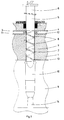
- Fig. 1 is a cross section of the mixing head, with the plunger in the mixing and injection position and the feed channels for the plastic components opened;
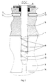
- Fig. 2 is a cross section of the mixing head, with the plunger in the recirculation position and the feed channels for the plastic components closed.
- As shown by fig.'s 1 and 2, the
mixing head 1 is provided with abore 2 in whichend channels 3 and 4 for supply of the separate plastic components, which after mixing react with each other to form a polymerized product. Thebore 2 accommodates aplunger 5, comprising apart 6 which fits closely in thebore 2 and apart 7 whose circumference is provided with helically runningribs 8. Theplunger 5 can rotate in two directions and can be moved axially. The mixinghead 1 is connected to amould 9. Thebore 2 of themixing head 1 connects to thegate 10 of themould 9. In thefeed channels 3 and 4 for the plastic components there are axiallymovable valves mixing chamber 2 can be opened and closed. - The mixing head functions as follows:
When the mixing starts theplunger 5 is in the position as shown in fig. 1. Theplunger 5 rotates and thechannels 3 and 4 for supply of the plastic components are opened. Thevalves mixing chamber 2 under pressure and are subjected to a return-pumping motion by theribs 8 ofplunger section 7. As the film layer formed is rubbed off and passes along theribs 8, very intensive intermixing of the components takes place. In spite of the return-pumping motion by theribs 8 the mass flow, owing to the supply under pressure of the components, moves to the free end of the plunger and via thegate 10 flows into themould 9. Thepart 7 of theplunger 5 provided withribs 8 is slightly tapered towards the free end. As a result, the thickness of thefilm layer 13 increases steadily, so that the pressure as well as the outflow speed decrease. When sufficient mixture of the components for a mould charge has been prepared, the rotating plunger moves forward. Immediately after this movement thevalves fitting part 6 of theplunger 5. The mixing chamber is thus cleansed. This position is shown in fig. 2. The rest of the mixture formed is injected into the mould. It is important that while the plunger moves forward towards the mould opening the rotating motion is maintained, since otherwise the mixture that passes last would not be mixed well. After injection into themould 9 and polymerization of the mixture the opposite rotating and axial motions of theplunger 5 are started. By these combined motions the part of theplunger 7 provided withribs 8 rotates out of the reacted portion in the gate. When the formed product has been taken out of themould 9, the cull is removed from the moulding. Theplunger 5 is then back in the position shown in fig.1; the feed channels are opened again and mixing of the components for the next mould charge can take place. - The apparatus and process according to the invention provide simply a fully self-cleansing mixing head for the mixing of chemically interreacting plastic components, with injection pressure independent mixing and pressure and speed decrease taking place in the mixing head. The turbulence occurring in the mixing head according to the invention is low, so that the mixture is injected with little turbulence into the mixing head. As a consequence, neither foaming nor air inclusion occurs when the mixing head is opened and during injection of the mixture into the mould.
Claims (6)
- Mixing head for mixing of at least two liquid chemically interreacting plastic components, comprising a casing provided with a mixing chamber containing an axially movable plunger (5), with two channels (3, 4) ending in the mixing chamber to feed in the plastic components, which mixing chamber is provided with a connection to a mould (9), wherein the plunger (5) can rotate and wherein over part of its length the plunger (5) fits closely in the mixing chamber, while the circumference of the rest of its length, up to the free end of the plunger, is provided with shear mixing means characterized in that the plunger can rotate into two directions and in that as shear mixing means helically running ribs (8) are provided.
- Mixing head according to claim 1, characterized in that the ribbed part of the plunger fits in the mixing chamber with minor play.
- Mixing head according to claims 1 and 2, characterized in that the ribbed part of the plunger is slightly tapered towards the free end.
- Mixing head according to claims 1-3, characterized in that during the mixing of the plastic components the ribbed part of the rotating plunger (5) is in the mixing chamber.
- Mixing head according to claims 1-4, characterized in that after the mixing of the plastic components the rotating plunger (5) is moved towards the gate (10) of the mould.
- Process for mixing of at least two chemically interreacting liquid plastic components with utilization of a mixing head according to one or more of the claims 1-5, wherein during the supply under pressure of the plastic components the part of the plunger (5) provided with shear mixing means is in the mixing chamber, while the mass flow of the components moves to the free end of the plunger (5) and via a gate (10) into the mould (9), after which, after mixing, the plunger (5) is moved axially towards the gate (10) and the rotating motion of the plunger (5) is stopped, the mixing chamber being cleansed by the close-fitting part of the plunger (5) and the rest of the mixture being injected into the mould (9) as the plunger (5) moves forward, after which the mixture polymerizes characterized in that, subsequently the opposite rotating and axial motions of the plunger (5) are started and the ribbed part of the plunger (5) rotates out of the polymerized mixture in the gate (10).
Applications Claiming Priority (2)
| Application Number | Priority Date | Filing Date | Title |
|---|---|---|---|
| NL9000889A NL9000889A (en) | 1990-04-13 | 1990-04-13 | MIXING HEAD FOR MIXING CHEMICALLY RESPONDING LIQUID PLASTIC COMPONENTS. |
| NL9000889 | 1990-04-13 |
Publications (2)
| Publication Number | Publication Date |
|---|---|
| EP0451921A1 EP0451921A1 (en) | 1991-10-16 |
| EP0451921B1 true EP0451921B1 (en) | 1995-01-04 |
Family
ID=19856936
Family Applications (1)
| Application Number | Title | Priority Date | Filing Date |
|---|---|---|---|
| EP91200827A Expired - Lifetime EP0451921B1 (en) | 1990-04-13 | 1991-04-10 | Mixing head for mixing of liquid chemically interreacting plastic components |
Country Status (3)
| Country | Link |
|---|---|
| EP (1) | EP0451921B1 (en) |
| DE (1) | DE69106420T2 (en) |
| NL (1) | NL9000889A (en) |
Cited By (2)
| Publication number | Priority date | Publication date | Assignee | Title |
|---|---|---|---|---|
| US7098179B2 (en) | 2001-10-22 | 2006-08-29 | Henkel Kommanditgesellschaft Auf Aktien (Henkel Kgaa) | Cotton active, dirt removing urethane-based polymers |
| KR20210141838A (en) * | 2020-05-14 | 2021-11-23 | 조일공업주식회사 | Mixing head |
Families Citing this family (5)
| Publication number | Priority date | Publication date | Assignee | Title |
|---|---|---|---|---|
| US5691295A (en) * | 1995-01-17 | 1997-11-25 | Cognis Gesellschaft Fuer Biotechnologie Mbh | Detergent compositions |
| DE19515039C2 (en) * | 1995-04-24 | 1998-10-01 | Krauss Maffei Ag | Device for mixing at least two chemically reactive plastic components |
| FR2784929A1 (en) * | 1998-09-11 | 2000-04-28 | Abel Belbati | Thermoset pressurization, mixing and distribution system is common to diverse activities including injection molding, coating and casting, in plant also employing new air-assisted thermoset spray gun |
| JP4199102B2 (en) | 2003-12-18 | 2008-12-17 | 東京エレクトロン株式会社 | Substrate processing method, substrate processing system, and developer supply nozzle |
| IT202000001168A1 (en) * | 2020-01-22 | 2021-07-22 | Persico Spa | DEVICE AND METHOD OF MIXING |
Family Cites Families (7)
| Publication number | Priority date | Publication date | Assignee | Title |
|---|---|---|---|---|
| FR1215477A (en) * | 1958-02-04 | 1960-04-19 | Degussa | Mixing dosing and application device for pasty substances |
| US3189325A (en) * | 1962-01-22 | 1965-06-15 | Levy Sidney | Mixing device |
| GB1154561A (en) * | 1965-03-10 | 1969-06-11 | Clarks Ltd | Improvements in or relating to the Manufacture of Plastic Articles. |
| DE2051109A1 (en) * | 1970-10-17 | 1972-04-20 | Nirona Werke Kg | Plastics mixing chamber cleaner - using pliable plug to scrape mixing tube and plug mould |
| DE2053684A1 (en) * | 1970-11-02 | 1972-05-10 | Baeumer Kg Spezialmasch | Plastics mixing unit - with single valve simultaneously operating both component inlets |
| US3843023A (en) * | 1973-09-17 | 1974-10-22 | D Vroom | Mixing and dispensing apparatus having nozzel cleaner |
| US3999740A (en) * | 1975-01-17 | 1976-12-28 | Mccorvey Raymond S | Mixing head |
-
1990
- 1990-04-13 NL NL9000889A patent/NL9000889A/en not_active Application Discontinuation
-
1991
- 1991-04-10 DE DE69106420T patent/DE69106420T2/en not_active Expired - Fee Related
- 1991-04-10 EP EP91200827A patent/EP0451921B1/en not_active Expired - Lifetime
Cited By (2)
| Publication number | Priority date | Publication date | Assignee | Title |
|---|---|---|---|---|
| US7098179B2 (en) | 2001-10-22 | 2006-08-29 | Henkel Kommanditgesellschaft Auf Aktien (Henkel Kgaa) | Cotton active, dirt removing urethane-based polymers |
| KR20210141838A (en) * | 2020-05-14 | 2021-11-23 | 조일공업주식회사 | Mixing head |
Also Published As
| Publication number | Publication date |
|---|---|
| DE69106420T2 (en) | 1995-05-04 |
| DE69106420D1 (en) | 1995-02-16 |
| EP0451921A1 (en) | 1991-10-16 |
| NL9000889A (en) | 1991-11-01 |
Similar Documents
| Publication | Publication Date | Title |
|---|---|---|
| US4275033A (en) | Apparatus for producing a reaction mixture containing fillers from at least two components which are capable of flowing | |
| USRE29665E (en) | Apparatus for ejecting a mixture of a plurality of liquids | |
| US4397407A (en) | Apparatus for the production of a solid-forming or foam-forming mixture composed of at least two flowable reaction components and fillers | |
| US3793416A (en) | Process for injection molding foam synthetic resin materials involving introduction of the expansion agent into the metering zone between injection molding steps | |
| US7169340B2 (en) | Resin and fiber compounding process for molding operations | |
| US4749554A (en) | Nozzle for mixing flowable reaction components | |
| US6875385B2 (en) | Method of compounding resin and fiber | |
| JPS6349412A (en) | Device for mixing at least two reacting plastic component and method of controlling said device | |
| US5858416A (en) | Process and device for manufacturing plastic parts with reinforcement fibers | |
| US4135870A (en) | Machine for producing additive containing plastic articles | |
| JPS62502253A (en) | High pressure kneading head and reactive component injection valve | |
| EP0451921B1 (en) | Mixing head for mixing of liquid chemically interreacting plastic components | |
| US4440500A (en) | High pressure impingement mixing apparatus | |
| US6431847B1 (en) | Apparatus for compounding resin and fiber | |
| US6065862A (en) | High-pressure mixing head | |
| US4486102A (en) | Mixing apparatus for multi-component plastics, especially polyurethane | |
| JPS5922635A (en) | Manufacture of reaction mixture and mixer head for said purpose | |
| US4680003A (en) | Apparatus for the production of moldings from flowable reactive components | |
| CA1094273A (en) | Control of plastic injection | |
| CN1822942B (en) | Molding method, purging method, and molding machine | |
| US6254813B1 (en) | Method and apparatus for injection molding plastic objects comprised of at least two different materials | |
| US3908966A (en) | Mixing apparatus | |
| US3709640A (en) | Means for the production of moulded components from chemical components whch react quickly with one another | |
| US4106113A (en) | Feeding screw assembly of a molding machine for plasticizing masses, particularly, for plastics or rubber | |
| US3609817A (en) | Moulding apparatus for thermosetting plastics material |
Legal Events
| Date | Code | Title | Description |
|---|---|---|---|
| PUAI | Public reference made under article 153(3) epc to a published international application that has entered the european phase |
Free format text: ORIGINAL CODE: 0009012 |
|
| AK | Designated contracting states |
Kind code of ref document: A1 Designated state(s): DE FR IT NL |
|
| 17P | Request for examination filed |
Effective date: 19920402 |
|
| 17Q | First examination report despatched |
Effective date: 19931006 |
|
| GRAA | (expected) grant |
Free format text: ORIGINAL CODE: 0009210 |
|
| AK | Designated contracting states |
Kind code of ref document: B1 Designated state(s): DE FR IT NL |
|
| PG25 | Lapsed in a contracting state [announced via postgrant information from national office to epo] |
Ref country code: IT Free format text: LAPSE BECAUSE OF FAILURE TO SUBMIT A TRANSLATION OF THE DESCRIPTION OR TO PAY THE FEE WITHIN THE PRE;WARNING: LAPSES OF ITALIAN PATENTS WITH EFFECTIVE DATE BEFORE 2007 MAY HAVE OCCURRED AT ANY TIME BEFORE 2007. THE CORRECT EFFECTIVE DATE MAY BE DIFFERENT FROM THE ONE RECORDED.SCRIBED TIME-LIMIT Effective date: 19950104 Ref country code: FR Effective date: 19950104 Ref country code: NL Effective date: 19950104 |
|
| REF | Corresponds to: |
Ref document number: 69106420 Country of ref document: DE Date of ref document: 19950216 |
|
| EN | Fr: translation not filed | ||
| NLV1 | Nl: lapsed or annulled due to failure to fulfill the requirements of art. 29p and 29m of the patents act | ||
| PLBE | No opposition filed within time limit |
Free format text: ORIGINAL CODE: 0009261 |
|
| STAA | Information on the status of an ep patent application or granted ep patent |
Free format text: STATUS: NO OPPOSITION FILED WITHIN TIME LIMIT |
|
| 26N | No opposition filed | ||
| PG25 | Lapsed in a contracting state [announced via postgrant information from national office to epo] |
Ref country code: DE Effective date: 19960103 |