US3695842A - Method and system for analyzing a liquid - Google Patents
Method and system for analyzing a liquid Download PDFInfo
- Publication number
- US3695842A US3695842A US19003A US3695842DA US3695842A US 3695842 A US3695842 A US 3695842A US 19003 A US19003 A US 19003A US 3695842D A US3695842D A US 3695842DA US 3695842 A US3695842 A US 3695842A
- Authority
- US
- United States
- Prior art keywords
- switch
- tube
- liquid
- blood
- time
- Prior art date
- Legal status (The legal status is an assumption and is not a legal conclusion. Google has not performed a legal analysis and makes no representation as to the accuracy of the status listed.)
- Expired - Lifetime
Links
- 239000007788 liquid Substances 0.000 title abstract description 61
- 238000000034 method Methods 0.000 title description 27
- 230000005291 magnetic effect Effects 0.000 abstract description 62
- 230000004907 flux Effects 0.000 abstract description 35
- 230000008859 change Effects 0.000 abstract description 18
- 230000033001 locomotion Effects 0.000 abstract description 17
- 239000007787 solid Substances 0.000 abstract description 15
- 238000004458 analytical method Methods 0.000 abstract description 13
- 238000001514 detection method Methods 0.000 abstract description 5
- 235000014676 Phragmites communis Nutrition 0.000 description 52
- 239000008280 blood Substances 0.000 description 39
- 210000004369 blood Anatomy 0.000 description 39
- 238000006243 chemical reaction Methods 0.000 description 34
- 238000012360 testing method Methods 0.000 description 26
- 244000273256 Phragmites communis Species 0.000 description 19
- 238000006073 displacement reaction Methods 0.000 description 19
- 230000035602 clotting Effects 0.000 description 18
- 239000004020 conductor Substances 0.000 description 14
- 206010053567 Coagulopathies Diseases 0.000 description 13
- 239000000463 material Substances 0.000 description 10
- 230000005294 ferromagnetic effect Effects 0.000 description 8
- 230000006870 function Effects 0.000 description 8
- 230000008569 process Effects 0.000 description 7
- 239000000853 adhesive Substances 0.000 description 6
- 230000001070 adhesive effect Effects 0.000 description 6
- 230000015271 coagulation Effects 0.000 description 6
- 238000005345 coagulation Methods 0.000 description 6
- 230000005484 gravity Effects 0.000 description 6
- 238000012802 pre-warming Methods 0.000 description 6
- 230000004888 barrier function Effects 0.000 description 5
- 238000001879 gelation Methods 0.000 description 5
- 238000007373 indentation Methods 0.000 description 5
- 230000004048 modification Effects 0.000 description 4
- 238000012986 modification Methods 0.000 description 4
- 239000004033 plastic Substances 0.000 description 4
- 229920003023 plastic Polymers 0.000 description 4
- 238000004804 winding Methods 0.000 description 4
- FAPWRFPIFSIZLT-UHFFFAOYSA-M Sodium chloride Chemical compound [Na+].[Cl-] FAPWRFPIFSIZLT-UHFFFAOYSA-M 0.000 description 3
- 230000023555 blood coagulation Effects 0.000 description 3
- 239000003795 chemical substances by application Substances 0.000 description 3
- 230000007423 decrease Effects 0.000 description 3
- 230000007812 deficiency Effects 0.000 description 3
- 230000001419 dependent effect Effects 0.000 description 3
- 238000010586 diagram Methods 0.000 description 3
- 239000003822 epoxy resin Substances 0.000 description 3
- 239000003302 ferromagnetic material Substances 0.000 description 3
- 238000010438 heat treatment Methods 0.000 description 3
- 230000002401 inhibitory effect Effects 0.000 description 3
- 239000000203 mixture Substances 0.000 description 3
- 229920000647 polyepoxide Polymers 0.000 description 3
- 230000009467 reduction Effects 0.000 description 3
- 230000002829 reductive effect Effects 0.000 description 3
- 238000009987 spinning Methods 0.000 description 3
- 239000000126 substance Substances 0.000 description 3
- 239000004698 Polyethylene Substances 0.000 description 2
- BQCADISMDOOEFD-UHFFFAOYSA-N Silver Chemical compound [Ag] BQCADISMDOOEFD-UHFFFAOYSA-N 0.000 description 2
- 230000009471 action Effects 0.000 description 2
- 238000013019 agitation Methods 0.000 description 2
- 229910052782 aluminium Inorganic materials 0.000 description 2
- XAGFODPZIPBFFR-UHFFFAOYSA-N aluminium Chemical compound [Al] XAGFODPZIPBFFR-UHFFFAOYSA-N 0.000 description 2
- 230000003321 amplification Effects 0.000 description 2
- 238000013459 approach Methods 0.000 description 2
- 230000015572 biosynthetic process Effects 0.000 description 2
- 230000000694 effects Effects 0.000 description 2
- 239000012530 fluid Substances 0.000 description 2
- 238000005755 formation reaction Methods 0.000 description 2
- 239000011521 glass Substances 0.000 description 2
- 238000009533 lab test Methods 0.000 description 2
- 229910052751 metal Inorganic materials 0.000 description 2
- 239000002184 metal Substances 0.000 description 2
- 238000002156 mixing Methods 0.000 description 2
- 238000003199 nucleic acid amplification method Methods 0.000 description 2
- 230000003534 oscillatory effect Effects 0.000 description 2
- 230000035699 permeability Effects 0.000 description 2
- -1 polyethylene Polymers 0.000 description 2
- 229920000573 polyethylene Polymers 0.000 description 2
- 238000006116 polymerization reaction Methods 0.000 description 2
- 229920001296 polysiloxane Polymers 0.000 description 2
- 229920005989 resin Polymers 0.000 description 2
- 239000011347 resin Substances 0.000 description 2
- 230000035945 sensitivity Effects 0.000 description 2
- 229910052709 silver Inorganic materials 0.000 description 2
- 239000004332 silver Substances 0.000 description 2
- 239000011780 sodium chloride Substances 0.000 description 2
- 239000001993 wax Substances 0.000 description 2
- 238000009736 wetting Methods 0.000 description 2
- 101100123850 Caenorhabditis elegans her-1 gene Proteins 0.000 description 1
- 102000004190 Enzymes Human genes 0.000 description 1
- 108090000790 Enzymes Proteins 0.000 description 1
- JOYRKODLDBILNP-UHFFFAOYSA-N Ethyl urethane Chemical compound CCOC(N)=O JOYRKODLDBILNP-UHFFFAOYSA-N 0.000 description 1
- HTTJABKRGRZYRN-UHFFFAOYSA-N Heparin Chemical compound OC1C(NC(=O)C)C(O)OC(COS(O)(=O)=O)C1OC1C(OS(O)(=O)=O)C(O)C(OC2C(C(OS(O)(=O)=O)C(OC3C(C(O)C(O)C(O3)C(O)=O)OS(O)(=O)=O)C(CO)O2)NS(O)(=O)=O)C(C(O)=O)O1 HTTJABKRGRZYRN-UHFFFAOYSA-N 0.000 description 1
- 239000004793 Polystyrene Substances 0.000 description 1
- 102100027378 Prothrombin Human genes 0.000 description 1
- 108010094028 Prothrombin Proteins 0.000 description 1
- 208000007536 Thrombosis Diseases 0.000 description 1
- 230000001133 acceleration Effects 0.000 description 1
- 239000003146 anticoagulant agent Substances 0.000 description 1
- 229940127219 anticoagulant drug Drugs 0.000 description 1
- 230000008901 benefit Effects 0.000 description 1
- 238000004159 blood analysis Methods 0.000 description 1
- 210000004556 brain Anatomy 0.000 description 1
- 239000004568 cement Substances 0.000 description 1
- 239000003153 chemical reaction reagent Substances 0.000 description 1
- 238000004140 cleaning Methods 0.000 description 1
- 238000003759 clinical diagnosis Methods 0.000 description 1
- 239000011248 coating agent Substances 0.000 description 1
- 238000000576 coating method Methods 0.000 description 1
- 239000000356 contaminant Substances 0.000 description 1
- 230000002526 effect on cardiovascular system Effects 0.000 description 1
- 229920001971 elastomer Polymers 0.000 description 1
- 230000005284 excitation Effects 0.000 description 1
- 210000003414 extremity Anatomy 0.000 description 1
- 239000006260 foam Substances 0.000 description 1
- 229960002897 heparin Drugs 0.000 description 1
- 229920000669 heparin Polymers 0.000 description 1
- 230000001771 impaired effect Effects 0.000 description 1
- 230000000977 initiatory effect Effects 0.000 description 1
- 239000012774 insulation material Substances 0.000 description 1
- 238000011005 laboratory method Methods 0.000 description 1
- 230000005389 magnetism Effects 0.000 description 1
- 238000004519 manufacturing process Methods 0.000 description 1
- 239000003550 marker Substances 0.000 description 1
- 239000002991 molded plastic Substances 0.000 description 1
- 230000003287 optical effect Effects 0.000 description 1
- 230000010355 oscillation Effects 0.000 description 1
- 230000007170 pathology Effects 0.000 description 1
- 229920001568 phenolic resin Polymers 0.000 description 1
- 230000019612 pigmentation Effects 0.000 description 1
- 239000006187 pill Substances 0.000 description 1
- 229920002223 polystyrene Polymers 0.000 description 1
- 229940039716 prothrombin Drugs 0.000 description 1
- 230000000717 retained effect Effects 0.000 description 1
- 238000007789 sealing Methods 0.000 description 1
- 238000000926 separation method Methods 0.000 description 1
- 239000013589 supplement Substances 0.000 description 1
- 238000001356 surgical procedure Methods 0.000 description 1
- 238000011287 therapeutic dose Methods 0.000 description 1
- 230000008719 thickening Effects 0.000 description 1
- 238000012546 transfer Methods 0.000 description 1
- 230000009466 transformation Effects 0.000 description 1
- 230000003313 weakening effect Effects 0.000 description 1
- 210000000707 wrist Anatomy 0.000 description 1
Images


Classifications
-
- G—PHYSICS
- G01—MEASURING; TESTING
- G01N—INVESTIGATING OR ANALYSING MATERIALS BY DETERMINING THEIR CHEMICAL OR PHYSICAL PROPERTIES
- G01N33/00—Investigating or analysing materials by specific methods not covered by groups G01N1/00 - G01N31/00
- G01N33/48—Biological material, e.g. blood, urine; Haemocytometers
- G01N33/483—Physical analysis of biological material
- G01N33/487—Physical analysis of biological material of liquid biological material
- G01N33/49—Blood
- G01N33/4905—Determining clotting time of blood
-
- G—PHYSICS
- G01—MEASURING; TESTING
- G01N—INVESTIGATING OR ANALYSING MATERIALS BY DETERMINING THEIR CHEMICAL OR PHYSICAL PROPERTIES
- G01N11/00—Investigating flow properties of materials, e.g. viscosity, plasticity; Analysing materials by determining flow properties
Definitions
- coagulation inhibiting agents may normally be administered to patients having suffered cardiovascular crises and certain surgical procedures. Accordingly, the time required for clot formation within a standard laboratory test tube has been interpreted as an indication of the level of such inhibiting agents within a patients circulatory system.
- blood coagulation tests may be considered to be in two basic categories.
- One of the categories involves analyzing the clotting or Prothrombin time of a mixture of anti-coagulated blood and standardized reagents which are added after the blood is drawn from the patient.
- the other category involves analyzing the clotting time of whole or venous blood including the foregoing inhibiting agents which have previously been administered to the patient.
- the clotting time is defined as the time between the time that the blood specimen is taken from the patient and the time of occurrence of the complete gelation of the blood specimen. It has previously been the practice for a technician to perform this time analysis manually in one or more laboratory test tubes according to the method of Lee and White, A Clinical Study of the Coagulation Time of Blood, American Journal of Medical Science, volume 145, pages 495-503, 1913. Other reference for this method are: Todd and Stanford, Clinical Diagnosis by Laboratory Methods, 14th edition, W. B.
- a Solid State Whole Blood Coagulation Time Device by Joseph Beeman, M.D., clotting time is determined optically by the interruption of a light beam to a photoelectric sensor.
- Such optical sensing techniques have been found by some investigators to be unreliable especially when low pigmentation or settling of pigmented components of the blood present a near colorless liquid to the sensing element.
- a system and method of analyzing a liquid as it transforms itself to a gelatinous or solid mass A member of magnetically permeable material is disposed within a zone containing the liquid and magnetic flux lines are passed through the member and the zone. A relative motion is produced between the zone and the member to agitate the liquid.
- the member When the liquid transforms itself the member is displaced from an initial predetermined position and this displacement is detected upon occurrence of a predetermined change in the magnetic flux lines.
- a signal is generated at the time of occurrence of the predetermined flux line change.
- the zone may comprise a reaction tube closed at least at one end with at least one member extending from the inner surface of the tube.
- the extending member provides a mechanical grip on the transformed liquid thereby gripping the transformed liquid to the inner surface.
- FIG. 1 illustrates the basic analyzer system of the tube, proximity detector and analyzer system
- FIGS. 2-7 illustrate in varying detail the structural features of the analyzer system 20 embodying the invention
- FIG. 8 illustrates an electrical block diagram of the analyzer system of FIGS. 2-7;
- FIG. 9 illustrates an electrical block diagram of a modification of FIG. 8.
- FIGS. 10-13 illustrate further embodiments of the invention in which the reaction tube is vertical
- FIGS. 14-16 illustrate further embodiments of the invention in which difiering structures grip the clot.
- FIG. 17 illustrates a still further embodiment of the invention of a differing shaped reaction vessel.
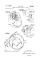
- FIG. 1 there is shown a basic system of analyzing a liquid as it transforms itself to a gelatinous or solid mass within a reaction zone such as a glass reaction tube 10.
- the particular liquid analyzed within tube may be blood 12 which transforms itself to a gelatinous mass.
- Tube 10 may be defined as being a nonmagnetically permeable vessel which is closed at least at one end.
- reaction tube 10 is cylindrically shaped and comprises an inner side wall 10a, an inner bottom surface 10b, an outer side wall 10c and an outer bottom surface 10d.
- wall 10a and surface 1% are defined as the inner surface 10zz-b of tube 10
- wall 10c and surface 10d are defined as the outer surface 10c-d of tube 10.
- the illustrated reaction tube 10 is of conventional type having substantially hemispheric inner and outer bottom surfaces 10b and d it will be understood that the bottom surfaces may have differing shapes such as flat for example.
- a member of magnetic permeable material is im mersed in blood 12 and lies on the inner surface 10a-b of tube 10.
- member 15 touches inner side wall 10a and inner bottom surface 1%.
- a magnetic field sensor such as a reed switch 17 is located beneath reaction tube 10 with the metal reeds 17ab of switch 17 preferably parallel to member 15.
- member 15 is a solid cylindrical plastic or wax coated permanent magnet and is the sole source of the magnetic flux lines which are effective to cause reeds 17a-b to close with magnet member 15 in its illustrated position.
- member 15 is a solid cylindrical plastic or wax coated permanent magnet and is the sole source of the magnetic flux lines which are effective to cause reeds 17a-b to close with magnet member 15 in its illustrated position.
- the forementioned magnetic flux line circuit between member 15 and reeds 17ab may only be formed if the materials comprising these components are characterized by magnetic permeability of magnitude substantially greater than that of the adjacent environment. In practice, such materials are typically of the class of abnormally high permeability materials known as ferromagnetic.
- switch 17 is maintained fixed or stationary and reaction tube 10 is rotated about its axis in the illustrated clockwise direction at a slow speed such as .25 r.p.m.
- member 15 rolls freely and remains substantially in its illustrated initial predetermined lowest position as a result of the force of gravity plus the mutual magnetic attraction of member 15 and reeds 17a-b.
- a relative motion between the inner surface 10a-b of reaction tube 10 as it rotates and member 15 which results in an agitation of blood 12.
- blood 12 as it rotates within reaction tube 10 is impeded in its rotational motion upon encountering member 15.
- blood 12 is forced to flow around member 15 and the blood is thereby agitated.
- gelatinous mass of coagulated blood forms adhesive forces and also mechanical forces between member 15 and inner surface Illa-b.
- member 15 departs or is displaced from its initial position.
- adhesive and mechanical forces are of sufficient magnitude to overcome the forces of gravity and mutual magnetic attraction maintaining member 15 in its initial position, then member 15 departs from such position.
- analyzer system 20 detects a change in the magnetic flux lines upon displacement of member 15 from its initial lowest position when blood 12 solidifies forming adhesive and mechanical forces of sufficient magnitude to overcome the gravitational and mutual magnetic forces maintaining the member in its initial position.
- switch 17 detects a change in the position of member 15 and may be defined as an electromagnetic proximity detector, sensitive to a predetermined displacement of member 15.
- Blood which has certain clotting deficiencies may not always provide sufiicient forces between member 15 and the smooth inner surface Illa-b to overcome the above described magnetic and gravitational forces.
- a particular example of such a deficiency is displayed by blood which has been treated with therapeutic doses of the anticoagulant, Heparin. Clots formed by heparinized blood appear to consist of filament and web-like structures that adhere readily to themselves but are attached to foreign surfaces only at their extremities. During formation of such clots the forces tending to maintain member 15 in its initial predetermined lowest position along inner side wall 10a may result in the failure of these fragile bonds. As reaction tube 10 continues to rotate thereafter there is produced a slipping motion of the entire clot relative to the inner surface 10a-b.
- inner side wall 10a may be effectively modified as shown in FIGS. 3, 3A and 5 by wedging a symmetrical plastic structure 14 into position Within tube 10.
- Structure 14 comprises four rectangular shaped fins 16 radially extending from a hub and a stem 18 extending from one end of the hub toward bottom surface 1%.
- a barrier disc 19 is formed at the other end of the hub to confine member 15 within the testing volume.
- Structure 14 is positioned so that the bottom edge of the fins are sufficiently above member 15 to allow clearance so that member 15 moves or rolls freely as tube 10 is rotated.
- fins 16 The function of fins 16 is to provide a mechanical grip on or adhesion to the clot thereb'y forcing the clot to rotate with the inner surface Illa-b of tube 10.
- member 15 When the clot has attained a sutficient degree of firmness, member 15 is similarly mechanically gripped or confined by the rotating clot and is thereby displaced upwardly from its initial normal position as tube 10 rotates. It is the detection of this displacement to a line above the centerline or axis of the tube which is used to electronically identify the end point condition of clot formation. It will be understood from the foregoing example of clotting deficiencies that such clot formations may be discretely rather than uniformly distributed throughout the blood 12. In such cases member 15 may be displaced in the described manner resulting in the identification of an end point condition other than one associated with complete gelation of the blood 12..
- stem 18 The purpose of stem 18 is to prevent member 15 from attaining a position along the axis of tube 10 since such displacement from the initial position to the axis may be insufiicient to deactuate switch 17.
- member 15 may be forced by the clotting blood in an objectionable spiral path from its initial position around and toward the tube axis instead of preferably rotating with inner wall 10a in a circular path around the axis. It will be understood that in such a circular path member 15 is displaced rapidly at a greater distance from switch 17 as compared with the spiral path.
- the materials comprising structure 14 and the coating of member 15 may be non-wetting and non-migrating substances such as polyethylene, silicone, or high temperature waxes.
- member 15 is first inserted into tube taking into consideration the magnetic pole direction required by switch 17. Structure 14 is then wedged into position within the tube and maintained in this location by frictional forces between inner side Wall 1011 and the outermost surfaces of fins 16.
- tube 10* After tube 10* has been assembled with structure 14 and member prior to use it may be prerinsed with a saline solution. Excess moisture is removed from the tube by a series of rapid wrist motions as in shaking down a thermometer. As will later be described in detail with respect to analyzer system shown in FIGS. 2-8 appropriate prewarming and timer reset procedures are followed and a blood specimen is taken from the patient by the use of a collecting syringe. The blood specimen is then transferred from the syringe to tube 10 filling it until the [fluid surface is approximately level with disc 19. The tube is then placed in a test cavity in the manner later to be described.
- tube 10, stopper 11, structure 14 and member 15 comprise an expendable specimen container system which is only usable for one analysis.
- the saline rinsing is accomplished at the time of manufacture after which a predetermined vacuum is drawn within tube 10h
- the specimen container system functions as its own specimen collecting syringe by the use of a doubleended hypodermic needle in the manner described in J. J. Kleiner, U.S. Pat. No. 2,460,641.
- One end of the needle is used to perform a vena puncture and the second to penetrate diaphragm 11a of stopper 11.
- the vacuum in tube 10 draws the required volume of blood into the tube as determined by the sealed free volume and degree of vacuum imposed.
- the fluid surface is approximately level with disc 19.
- ANALYZER SYSTEM 20 Referring now to FIGS. 2-8 there is shown an analyzer system 20 according to the invention which is capable of analyzing the coagulation time of blood as well as other liquids which transform themselves from a liquid to a gelatinous or solid mass.
- analyzer system 20 has been specifically designed for the convenience of a medical technician in the performance of routine whole blood coagulation analysis.
- Analyzer system 20 comprises a metal housing 21 having a sloping front panel 21a and an opening 21b into which reaction tube 10 is inserted.
- Tube 10 is received in an incubator test cavity 26 comprising a hollow aluminum cylinder 22.
- Closely formed above cylinder 22 is a box-like housing 23 formed of sheet aluminum in a substantially rectangular shape.
- Reed switch 17 is cemented or otherwise secured to the lower outer wall of cylinder 22 and switch 17 is in its previously described position with respect to tube 10 and member 15 with the tube in test cavity 26.
- Heater wire 24 is wound in a bifilar manner about the periphery of cylinder 22, housing 23 and switch 17.
- Cylinder 22 is formed having a closed lower end 22a adjacent tube bottom surface 10d and an open upper end received in an opening 25a of a phenolic plastic contact and mounting block 25.
- a pair of screws 27c and 280 are threadedly engaged in an upper end of block 25 and extend into opening 25a.
- Screws 27c and 280 each comprise one terminal of normally open switch 27 and normally closed switch 28 respectively.
- the other terminal of each switch 27-28 comprises bimetallic thermostat leaves 27a and 28a respectively having secured to one end thereof silver contacts 2711-2811 respectively.
- the other ends of leaves 27a-28a are secured to housing 23.
- Contacts 27b-28b are adapted to engage the ends of screws 270-280 respectively which are silver tipped.
- an additional magnet may be used to provide reed switch 117 with a magnetic bias.
- magnet 29 is secured to housing end 23a.
- This magnetic bias is not sufiicient without the magnetic force of magnet member 15 to close reeds 17a-b.
- this magnetic bias is not so strong as to maintain reeds 17ab in a closed position when member 15 is displaced from its initial position as previously described.
- the purpose of the magnetic bias is to adjust the sensitivity of switch 17 to displacements of member 15 and thus magnet 29 may be used to supplement the magnetic flux of member 15 in cases where member 15 has a low magnetic flux value and may have difiiculty alone in closing the switch.
- by reversing the pole position of bias magnet 29 it is effective to decrease the magnetic flux of member 15 in those cases where the member provides an excessive magnetic flux.
- an insulation material such as urethane foam 31 is wrapped around the exposed outer side walls and lower surfaces 22a and 23a of cylinder 22 and housing 23, respectively.
- a chronographic escapement or elapsed time meter 50" comprises a manual reset lever 51, a chronometer drive motor 54, a timer escapement plate 55 and a rotating drum 56.
- Drive motor 54 is secured in timer housing 53 the top face 53a of which is fixed to support chassis 32 by means of cylindrical support members 58.
- One side of circular escapement plate 55 is secured to a front face 53b of housing 53 so that the plate is rigidly held in a plane perpendicular to the plane of panel lla.
- Reed switches 60 and 61 are radially (llS- posed and fixedly secured to the other side of plate 55 remote from housing 53.
- Reed switch 60 is a normally open low time limit switch while reed switch 61 is a normally closed high time limit switch.
- Switch 61 1s mamtained normally closed as a result of the placement of a bias magnet 62 adjacent and parallel to the switch. Magnet 62 is disposed within an indentation in plate 55 and secured therein with cement for example.
- a timer shaft 64 of drive motor 54 extends out of housing face 53b and rotates at a uniformly precise speed as for example one revolution per hour.
- Shaft 64 is received and secured within an opening in a hub 66 fixed to the center of a disc shaped portion 56a of drum 56.
- a magnet 67 is received within an opening 68 formed radially of and through both sides of the disc shaped portion 56a.
- Drum 56 also includes a cylindrical timer scale 56b having one edge secured to the periphery of disc portion 56a.
- a counterweight 560 is secured to disc portion 56a substantially opposite magnet 67 in order to effectively balance the weight about shaft 64.
- drum 56 When in its initial position drum 56 is rotated so that magnet 67 is adjacent reed switch 60 and the zero time marking on scale 56b is then lined up with marker 52 on panel 2 1a.
- elapsed time meter 50 is zeroed by actuating manual reset lever 51 and the reeds of switch 60 close. Since reed switches normally have an amount of hysteresis, the reeds of switch 60 remain closed, once thrown, as drum 56 rotates away from the switch until approximately two and one-half minutes have elapsed.
- Switch 61 is maintained normally closed by bias magnet 62 until drum 56 rotates almost a complete rotation and magnet 67 short circuits magnet 62 and allows the reeds of switch 61 to open.
- one terminal or reed of each of switches 60 and 61 is connected to a junction 71 which is coupled to one terminal or reed 17a of switch 17.
- the other terminal or reed 17b is connected by way of conductor 69, switch 27, junction 7 1a, switch 28, and conductor 70a to an input terminal 74b of amplifier '74.
- Amplifier 74 is a part of a current amplification circuit 72 and operates to produce an output signal at output terminal 74c upon application (1) of a supply current to power terminal 74a and (2) an input signal to input terminal 74b. In this manner amplifier 74 eifectively operates as an AND gate.
- Circuit 72 also includes a relay 76 having normally open switch terminals 7 6a-b and input terminal 760 connected to output terminal 740. Upon application of an input signal to terminal 760, relay 76 is switched to close terminals 76a-b.
- Switch 27 operates as an interlock switch in that it is normally open until the temperature in test cavity 26 has increased to a predetermined value at which time the switch closes.
- Switch 28 operates as a normally closed thermostat switch which opens when the temperature in test cavity 26 has increased to a predetermined value. Switches 27 and 28 are adjusted so that as the test cavity temperature increases in value, switch 27 closes before switch 28 opens with a preferred temperature separation of about 5 degrees F.
- a battery 80 has a positive terminal 80a connected to ground and a negative supply terminal 80b connected by way of a conductor 81 to terminal 76a and to the other terminal or read of switch 61.
- a battery charger 82 is contained within the housing 21 and is provided with a plug 83 for connection with a conventional AC wall outlet. In this manner, after battery 80 has been charged, system 20' is fully portable with a self contained source of supply and is not dependent upon the availability of a wall outlet. The operation of system 20 will first be described with respect to the following Table A.
- heater 24 O/X 0 X (0) 0 Heater 24 ofi.
- heater wire 24 is effective to heat cavity 26 until normally open interlock 27 closes and the prewarming is completed (state 2).
- switch 27 closed the negative potential is applied from terminal 71a through switch 27, conductors 69 and 69a to chronometer motor 54 and motor assembly 45 both connected in parallel to ground.
- a light bulb 85 is connected in shunt with motors 54 and 45. Accordingly when switch 27 closes motors 45 and 54 and bulb 85 are energized. The lighting of bulb 85,
- thermostat switch 28 controls the heat in cavity 26 so that when the temperature increases in value sufiiciently to open the switch, relay 76 then opens which deenergizes the heater circuit (state 2A).
- the negative potential is no longer supplied to conductors 69 and 69a and (1) elapsed time meter 54 and motor assembly 45 stop, and (2) amplifier 74 is deenergized thereby opening relay 76 and deenergizing the heater control circuit comprising current amplification circuit 72 and thermostat switch 28.
- the elapsed time read on scale 56b indicates the time of clot formation and analyzer system 20 is deenergized and ready for another analysis. If another test is not run, the cavity temperature decreases in value until switch 27 opens and the system returns to the cold, inactive state (state 7).
- Table C the operation of system 20 is described in which heater 24 latches out.
- Table C sets forth the sequence in which during the proximity switch 17 control mode (state 5) the system runs cold and interlock switch 27 opens (state 5').
- the reason for the system running cold may occur, for example, from battery approaching charge depletion. Accordingly, the system continues in the normal manner with motors 45 and 54 energized until the clot is detected. The motors are then deenergized and the system returns to the cold, inactive state which is indicated in Table C as states 6B-7B which is the same as state 7 of Table A.
- FIG. 9 ANALYZER SYSTEM It will be understood that the detection of predetermined changes in the magnetic flux lines which pass through tube 10 may be detected by devices other than reed switch 17.
- switch 17 is replaced by a conventional differential displacement transformer 88 which may be used together with an exciter-detector and switching system 90.
- Transformer '88 comprises an exciter coil or primary winding 88a and a pickup coil or secondary windings 88b and is mounted in a position similar to switch 17 illustrated in FIG. 3.
- magnetically permeable member 15 may or may not be permanently magnetized and acts as the core of transformer 8-8.
- oscillator 92 Upon application of a DC source supply to its input terminal 92a, oscillator 92 produces an excitation signal at signal terminals 92b which are applied to exciter coil 88a. Accordingly coil 88a produces an oscillating magnetic field, forming a circuit of magnetic flux lines between coil 88a and member 15 through the inner and outer surfaces of tube 10. As in the manner previously described, mem- 1 1 her 1'5 is maintained in its initial position as a result of the combined forces of gravity and magnetism.
- Pickup coil 88b comprises a pair of secondary windings which are connected in series opposition and coupled to exciter coil 88:: by way of the magnetic flux line circuit passing through member 15.
- the ability of transformer 88 to conduct electrical energy from oscillator 92 is substantially reduced.
- detector amplifier 91 the input of-Which is coupled to coil 8 produces a voltage inversely proportional to the displacement of member 15 from the initial position.
- the output of detector amplifier 91 is applied to the winding 94 of a relay 93 which is deactuated when there is a predetermined change in the flux lines upon displacement of the member from its initial position.
- the normally open switched contacts 93a-b are connected in a manner similar to that of switch 17. Specifically, contact 93a is connected to junction 71 and contact 93b is connected to conductors 69 and 6911.
- the supply terminal 921: for oscillator 92 and supply terminal 91a for detector amplifier "91 are connected to conductors 69 and 69a so that circuits 92 and 9 1 are supplied with power only during the times motors 45 and 54 are energized.
- FIGS. 10-13 Instead of being inclined from the vertical as-shown in FIGS. 1-3, tube 10 may be maintained in an upright or vertical position. As shown in FIG. 10, member is disposed at the bottom of tube 10. Magnetic pole extensions 17cd extend from reeds 17a-b respectively with reed switch 17 being fixed in an upright or vertical position. Pole extension 17d extends from reed 17b to approximately the center of bottom surface 10d while pole extension 170 extends from reed 17a to a position on outer side wall 100.
- Magnetic forces between pole extension 17c and the upper end of member 15 normally causes member 15 to assume a slightly inclined orientation so that a completed magnetic flux line circuit is provided between member 15, pole extensions 17c-d and reed switch 17.
- member 15 is maintained in its illustrated initial position by means of magnetic forces and is not dependent on gravity. Thus, higher speeds of rotation of tube 10 may be provided with member 15 being maintained in its initial position solely by magnetic forces.
- liquid '12 transforms itself member 15 departs from the initial or predetermined position and reed switch 17 opens.
- reed switch 17 may be replaced with a differential displacement transformer 88 as shown in FIG. 11 with transformer 88 being described with respect to FIG. 9.
- Transformer 88 includes an exciter coil 88a, a pickup coil 8811, a core 88:2, and specifically designed pole extensions 8 8cd.
- Pole extensions 88c-d are located similarly to pole extensions 17a-d.
- member 15 is slightly inclined to provide a completed magnetic circuit between the member, pole extensions 8-8c-d and core 882.
- relay 93 upon displacement of member 15 and from its initial position relay 93 is deactuated.
- tube 110 has a fiat-bottom 110a and permanent magnet 15a rests horizontally on the flat bottom.
- Member 115:: is of length less than the inner diameter of tube 110.
- Reed switch 17 is fixed in a horizontal position below bottom 110a with equal length magnetic pole extensions 17a-f extending vertically from reeds 17a-b respectively. Accordingly, it will be understood that a completed magnetic circuit is provided by way of member 15a, pole extensions 17ef and reed switch 17.
- adhesive and mechanical forces are formed between member 15a, the adjacent inner side wall and the inner surface of tube bottom 110a.
- a diiferential displacement transformer may be used to detect a change in the position of member 15 when the liquid transforms itself.
- a cylindrical magnet member 15b is secured to a structure 111 which comprises a spinner leg 112 and a buoyant node 114. Structure 111 is constructed so that it turns freely in an upright position when immersed in liquid 12.
- Switch 17 is disposed horizontally below tube 10 and secured to a rotatable turn table 144. Pole extensions 17g-h of L-shape extend from reeds 17a-b respectively to opposing positions on side wall to closely approach member 15b extending longitudinally therebet-ween.
- a completed magnetic circuit is provided between member 15b, pole extensions 17g-h and switch 17.
- Motor assembly 145 is effective upon energization to rotate table 144 thereby to rotate switch 17 and pole pieces 17g-h about the same axis as the axis of symmetry of tube 10. Accordingly, magnetic member 15b is magnetically attracted to and rotates wtih pole extensions 17g-h while tube 10 is maintained fixed.
- a commutator 146 is used to connect reeds 17ab to analyzer system 20.
- substantially fast speeds may be achieved as compared with the rotating tube assembly previously described.
- the mixing of liquid 12 is achieved by the relative movement between tube 10 and member 15b. Liquid 12 is being continually sheared between the stationary tube and the moving member 15b and is therefore agitated. For all practical mixing purposes, there is no basic difference between moving the member and maintaining the tube fixed or rotating the tube and maintaining the member in a fixed position. In FIG. 13, when the liquid transforms itself, the change in the flux lines is detected as member 15b adheres to the inner surfaces 10a-b and thus departs from its predetermined position between pole extensions 17g-h.
- member 15b may be accomplished without the requirement of structure 111 as for example in FIG. 12, tube may be held fixed while switch 17 and extension 17e-f are rotated thereby rotating or spinning member 15b.
- FIGS. 14-17 It will be understood that structure 14 of FIGS. 3, 3A and 5 may be modified while still providing the gripping function on the clot.
- any number of fins may be used, as for example, six rectangular shaped fins 16a of structure 14a in FIG. 14.
- the maximum number and the width of the fins are limited by the requirement that the gripping action by the fins on the clot not be impaired by so weakening the integrity of the clot that it is sheared above member 15.
- member 15 is contained within the test or reaction volume as a result of the interference provided by fins 16a without requiring a barrier disc. Specifically the spacing between fins 16a is not suificient to allow member 15 to pass through.
- the gripping action may also be provided by extensions or indentations 14b formed at the same height in inner and outer side walls 10a and c.
- Indentations 14b may be of such width and extend into tube 10 sufiiciently to provide a barrier for member 15.
- the barrier or confining feature is not essential if the technician excercises care to insure that member 15 is within the test volume.
- the stem has been eliminated which may be suitable, for example, with a relatively large tube 10 diameter where the sensitivity of switch 17 permits identification of member 15 displacement from the initial position to a position coaxial with tube 10.
- FIG. 16 Another modification of structure 14 not having the confining or stem feature is shown in FIG. 16 in which there is provided a single fin 14c bent slightly to provide the frictional forces between wall 10a and the outermost surfaces of the fin. It will now be understood that still further modifications of structure 14 (not shown) may be provided in which at least one member extends from inner side wall 10a projecting inwardly such as a multiplicity of radially directed plastic filaments or bristles.
- tube 10 may be made of materials other than glass which are nonmagnetically permeable and which do not effect the clotting process in an undesirable manner such as polyethylene or polystyrene, or that the inner surfaces 10a-b of tube 10 may be treated by chemical or heat cleaning procedures, or that these surfaces may be coated with a nonreacting material such as silicone for example.
- Tube 10 which provides a zone for liquid 12 may have shapes other than those previously described.
- the fixed zone for the liquid may have a substantially pill box shape and may be formed as an integral molded plastic reaction tube 150.
- extending from inner side wall 150a are a plurality of ribs or fins 152 which are similar to the extensions 14b of FIG. 15.
- Member 15 is free to rotate in a circular indentation formed in the inner bottom surface 150d of tube 150. The diameter of the circular opening is greater in value than the length of member 15.
- Member 15 may be rotated with respect to fixed tube 150 by means of a motor assembly 145, plate 144 (FIG. 13) having secured thereto reed switch 17 and pole extensions 17eof FIG. 12.
- rotation of the reaction tubes 10, 110, 150 or of reed switch 17 or transformer 88, as in FIG. 13 may be in either clockwise or counter-clockwise directions.
- Such motion may also be of a uniform oscillatory type provided that the degree of rotation in alternate directions causes suflicient displacement of magnetic member 15 when a clot has been formed to be detected by reed switch 17 or displacement transformer 88.
- such displacement may be plus and minus 90 degrees for a total of 180 degrees.
- the total period of oscillation may be, for example, two minutes.
- a method of analyzing a liquid as it transforms itself to a gelatinous or solid mass in which a variable conductance device is disposed adjacent to a zone containing said liquid and a member of ferromatic material is disposed within the zone comprising the steps of forming a circuit of magnetic flux lines between the device and the member,
- a system of analyzing a liquid as it transforms itself to a gelatinous or solid mass comprising a zone containing said liquid
- variable conductance means magnetically coupled through the walls of the zone to said member by way of magnetic flux lines for varying the electrical conductance upon change in said magnetic flux lines when the liquid transforms itself and said member changes position
- a system of analyzing a liquid as it transforms itself to a gelatinous or solid mass comprising a zone containing said liquid
- variable conductance means magnetically coupled through the surface of the zone to said member by way of magnetic flux lines for varying the electrical conductance upon change in said magnetic flux lines when the liquid transforms itself and said member changes position relative to said conductance means
- an independent energy source connected to said conductance means for providing through said conductance means an electrical energy flow which changes upon variation in the conductance of said conductance means
- variable conductance means formed to closely approach ends of said member thereby to provide a substantial magnetic force for maintaining 15 said member in a predetermined position relative to said variable conductance means.
- variable conductance means includes a source of magnetic flux lines to couple said variable conductance means to said member through the surface of the zone.
- variable conductance means comprises a displacement transformer
- said source of electrical energy comprises means for exciting said transformers.
- timing means which is actuated when said liquid is in a state ready to begin analysis for beginning a time period and for terminating the time period upon said signal being generated.
- variable conductance means comprises a reed switch maintained (1) closed when said member is in a predetermined position relative to said conductance means and (2) open upon occurrence of said change in magnetic flux lines when said member is displaced thereby producing a substantial change in the electrical conductance of said reed switch, and
- said ferromagnetic member comprises a source of magnetic flux lines to couple said variable conductance means to said member.
- said zone comprises a cylindrically shaped reaction tube having an inner surface and at least one member extending from said inner surface to provide a mechanical grip on said transformed liquid to said inner surface, said extending member being positioned to allow clearance for the movement of said ferromagnetic member as it changes position relative to said inner surface.
- variable conductance means comprises a magnetic proximity detector disposed adjacent to said zone whereby said magnetic flux lines provide a magnetic force tending to maintain said member in a predetermined position relative to said proximity detector.
- said proximity detector comprises reed switch means maintained in a closed circuit position by said magnetic flux lines with said member in said predetermined position.
- a second terminal of said reed switch being connected to (1) thermostat switch means for controlling said heating means and (2) said rotating means whereby with said reed switch closed the temperature of said heating means is controlled and said vessel is rotated.
- timing means comprises a chronometer drive motor for rotating timing indicia and a low time limit switch which is turned on at the beginning of the time period and is maintained on for a short perod of time thereafter, said limit switch being connected between said source and said thermostat switch means and said rotating means whereby said test cavity is heated and said vessel is rotated for said short time period preparatory to said vessel being inserted in said cavity.
- a nonferromagnetic reaction tube closed at least at one end for containing a liquid in which the time duration it takes for the liquid to transform itself to a gelatinous or solid mass is analyzed comprising said reaction tube having inner surface
- a ferromagnetic member disposed within said reaction tube and free to move relative to said inner surface
- reaction tube of claim 26 in which there is provided a fixed member disposed on the axis of symmetry of said tube to prevent said ferromagnetic member from attaining a position along the axis of said tube.
- reaction tube of claim 26 in which said extending member comprises a plurality of shaped fins radially extending from said axis of said vessel with each fin frictionally engaging said tube inner surface.
- reaction tube of claim 26 in which said extending member comprises at least one indentation formed in said inner surface of said tube.
- reaction tube of claim 26 in which said extending member comprises a single fin extending within said tube and frictionally engaging at opposing ends thereof said inner surface of said tube.
- reaction tube of claim 26 in which said extending member comprises at least one extension of said inner surface of said reaction tube.
- reaction tube of claim 26 in which there is provided containment means to confine said ferromagnetic member within a test volume.
Landscapes
- Health & Medical Sciences (AREA)
- Life Sciences & Earth Sciences (AREA)
- Engineering & Computer Science (AREA)
- Biomedical Technology (AREA)
- Chemical & Material Sciences (AREA)
- Physics & Mathematics (AREA)
- General Health & Medical Sciences (AREA)
- General Physics & Mathematics (AREA)
- Immunology (AREA)
- Pathology (AREA)
- Biochemistry (AREA)
- Hematology (AREA)
- Analytical Chemistry (AREA)
- Ecology (AREA)
- Biophysics (AREA)
- Molecular Biology (AREA)
- Urology & Nephrology (AREA)
- Food Science & Technology (AREA)
- Medicinal Chemistry (AREA)
- Investigating Or Analysing Biological Materials (AREA)
Applications Claiming Priority (2)
| Application Number | Priority Date | Filing Date | Title |
|---|---|---|---|
| US1900370A | 1970-03-12 | 1970-03-12 | |
| US00293396A US3836333A (en) | 1970-03-12 | 1972-09-29 | System for timing the coagulation of blood |
Publications (1)
| Publication Number | Publication Date |
|---|---|
| US3695842A true US3695842A (en) | 1972-10-03 |
Family
ID=26691720
Family Applications (2)
| Application Number | Title | Priority Date | Filing Date |
|---|---|---|---|
| US19003A Expired - Lifetime US3695842A (en) | 1970-03-12 | 1970-03-12 | Method and system for analyzing a liquid |
| US00293396A Expired - Lifetime US3836333A (en) | 1970-03-12 | 1972-09-29 | System for timing the coagulation of blood |
Family Applications After (1)
| Application Number | Title | Priority Date | Filing Date |
|---|---|---|---|
| US00293396A Expired - Lifetime US3836333A (en) | 1970-03-12 | 1972-09-29 | System for timing the coagulation of blood |
Country Status (4)
| Country | Link |
|---|---|
| US (2) | US3695842A (OSRAM) |
| CA (1) | CA957866A (OSRAM) |
| FR (1) | FR2084482A5 (OSRAM) |
| GB (1) | GB1322412A (OSRAM) |
Cited By (38)
| Publication number | Priority date | Publication date | Assignee | Title |
|---|---|---|---|---|
| US3824841A (en) * | 1971-02-08 | 1974-07-23 | Coulter Electronics | Method for sedimentation study |
| US3909201A (en) * | 1972-07-13 | 1975-09-30 | Centre Nat Transfusion | Analysis apparatus |
| US4000972A (en) * | 1976-01-16 | 1977-01-04 | Hemotec, Inc. | Measuring system for the pharmacological manipulation of the coagulation mechanism in blood and for the elapsed coagulation time |
| FR2402874A2 (fr) * | 1977-09-13 | 1979-04-06 | Hellige & Co Gmbh F | Procede et dispositif de mesure des changements d'etat dans les liquides en cours de coagulation |
| US4276383A (en) * | 1979-08-02 | 1981-06-30 | The United States Of America As Represented By The Department Of Health, Education & Welfare | Clot lysing timer |
| FR2516658A1 (fr) * | 1981-11-19 | 1983-05-20 | Behnk Holger | Appareil et procede pour detecter et mesurer le temps de coagulation du sang |
| US4523083A (en) * | 1981-07-29 | 1985-06-11 | Hamilton-Dunn Research Co. | Beverage warmer |
| US4533519A (en) * | 1983-07-20 | 1985-08-06 | Hemotec, Inc. | Gas flow coagulation test cartridge having movable member establishing communication between reagent and reaction chambers |
| USD285113S (en) | 1983-11-25 | 1986-08-12 | Warner-Lambert Technologies, Inc. | Urinometer |
| US4663127A (en) * | 1982-10-15 | 1987-05-05 | Hemotec, Inc. | Gas flow cartridge having resilient flexible membrane with slit separating reaction and reagent chambers |
| US4849340A (en) * | 1987-04-03 | 1989-07-18 | Cardiovascular Diagnostics, Inc. | Reaction system element and method for performing prothrombin time assay |
| US5154082A (en) * | 1991-05-20 | 1992-10-13 | International Technidyne Corporation | Microprocessor-controlled apparatus and method for detecting the coagulation of blood |
| US5174961A (en) * | 1991-01-18 | 1992-12-29 | Hemotec, Inc. | High sensitivity coagulation detection apparatus |
| US5271898A (en) * | 1993-05-03 | 1993-12-21 | Medtronic, Inc. | Apparatus for testing blood/biomaterials/device interactions and characteristics |
| US5302348A (en) * | 1992-12-10 | 1994-04-12 | Itc Corporation | Blood coagulation time test apparatus and method |
| US5314826A (en) * | 1991-08-23 | 1994-05-24 | Medtronic Hemotec, Inc. | Platelet activation and function evaluation technique |
| US5447440A (en) * | 1993-10-28 | 1995-09-05 | I-Stat Corporation | Apparatus for assaying viscosity changes in fluid samples and method of conducting same |
| US5526111A (en) * | 1993-08-31 | 1996-06-11 | Boehringer Mannheim Corporation | Method and apparatus for calculating a coagulation characteristic of a sample of blood a blood fraction or a control |
| US5601995A (en) * | 1992-09-04 | 1997-02-11 | Gradipore Limited | Apparatus and method for detecting coagulation in blood samples |
| EP0720439A4 (en) * | 1993-08-31 | 1997-09-24 | Boehringer Mannheim Corp | POWER SUPPLY CONTROL AND CONTROL FOR MEDICAL INSTRUMENT |
| US5686659A (en) * | 1993-08-31 | 1997-11-11 | Boehringer Mannheim Corporation | Fluid dose flow and coagulation sensor for medical instrument |
| US5800781A (en) * | 1994-10-21 | 1998-09-01 | International Technidyne Corporation | Blood sampling device |
| US5832921A (en) * | 1993-08-31 | 1998-11-10 | Boehringer Mannheim Corporation | Analog heater control for medical instrument |
| US5841023A (en) * | 1993-08-31 | 1998-11-24 | Boehringer Mannheim Corporation | Magnet for medical instrument |
| US5925319A (en) * | 1996-04-30 | 1999-07-20 | Medtronic, Inc. | Test cartridge for evaluating blood platelet functionality |
| US6114135A (en) * | 1991-11-08 | 2000-09-05 | Goldstein; Sheldon | Multiple coagulation test system and method of using a multiple coagulation test system |
| US6136271A (en) * | 1998-02-23 | 2000-10-24 | International Technidyne Corporation | Solid state apparatus employing hall effect sensors for detecting the coagulation of blood |
| US6417004B1 (en) * | 1999-04-29 | 2002-07-09 | Helena Laboratories Corporation | Enhancing clot detection in activated clotting time and other fibrin endpoint based tests |
| US20030180824A1 (en) * | 2002-03-25 | 2003-09-25 | Mpock Emmanuel C. | System for performing blood coagulation assays and measuring blood clotting times |
| WO2005106466A1 (en) * | 2004-04-19 | 2005-11-10 | Medtronic, Inc. | Blood coagulation test cartridge, system, and method |
| US20060016701A1 (en) * | 2004-05-17 | 2006-01-26 | Wei Qin | Point of care heparin determination system |
| US7399637B2 (en) | 2004-04-19 | 2008-07-15 | Medtronic, Inc. | Blood coagulation test cartridge, system, and method |
| US7439069B2 (en) | 2004-02-27 | 2008-10-21 | Nippoldt Douglas D | Blood coagulation test cartridge, system, and method |
| US8697449B2 (en) | 2011-04-01 | 2014-04-15 | Spectral Sciences, Inc. | Optical blood coagulation monitor and method |
| WO2017044055A1 (en) | 2015-09-08 | 2017-03-16 | Elbuken Caglar | Blood coagulation time measurement method and apparatus |
| US10001495B2 (en) | 2012-07-25 | 2018-06-19 | Bioverativ Therapeutics Inc. | Blood factor monitoring assay and uses thereof |
| US10739239B1 (en) * | 2013-10-28 | 2020-08-11 | Ifirst Medical Technologies, Inc. | Rotating magnetic disc medical analyzer and coagulation profiler |
| US12277814B2 (en) | 2020-01-29 | 2025-04-15 | Ifirst Medical Technologies, Inc. | Medical analyzer and diagnostic sample profiler |
Families Citing this family (13)
| Publication number | Priority date | Publication date | Assignee | Title |
|---|---|---|---|---|
| US4135818A (en) * | 1975-01-22 | 1979-01-23 | Bio/Data Corporation | Platelet aggregation monitoring device |
| FR2318421A1 (fr) * | 1975-07-16 | 1977-02-11 | Girolami Antoine | Procede et appareil de mesure du temps de variation de l'etat physique d'un corps ou milieu |
| EP0144437B1 (en) * | 1983-05-31 | 1988-08-10 | HIRATA, Keisuke | Rheometer |
| US5092677A (en) * | 1989-08-02 | 1992-03-03 | Artel, Inc. | Photometer having a long lamp life, reduced warm-up period and resonant frequency mixing |
| US5366869A (en) * | 1991-11-08 | 1994-11-22 | Sheldon Goldstein | Multiple coagulation test device and method |
| US5394739A (en) * | 1994-06-06 | 1995-03-07 | Computational Systems, Inc. | Viscosity tester and method with orbiting object |
| US5731212A (en) * | 1994-12-20 | 1998-03-24 | International Technidyne Corporation | Test apparatus and method for testing cuvette accommodated samples |
| US5629209A (en) * | 1995-10-19 | 1997-05-13 | Braun, Sr.; Walter J. | Method and apparatus for detecting viscosity changes in fluids |
| DE10203386A1 (de) * | 2002-01-29 | 2003-07-31 | Basf Ag | Einteilige Verschlussvorrichtung aus PVC |
| US8372343B2 (en) * | 2007-12-07 | 2013-02-12 | Sheldon Goldstein | Multiple coagulation test cartridge and method of using same |
| GB201416944D0 (en) * | 2014-09-25 | 2014-11-12 | Benson Viscometers Ltd | An Apparatus for monitoring blood coagulation |
| US10429377B1 (en) | 2019-03-15 | 2019-10-01 | Coagulation Sciences Llc | Coagulation test device, system, and method of use |
| CN115078702B (zh) * | 2021-03-12 | 2025-01-14 | 重庆南方数控设备股份有限公司 | 一种基于磁珠的血栓弹力图检测装置及方法 |
Family Cites Families (3)
| Publication number | Priority date | Publication date | Assignee | Title |
|---|---|---|---|---|
| US3053078A (en) * | 1958-04-17 | 1962-09-11 | Warren R Jewett | Apparatus for testing biological and other fluids |
| US3492096A (en) * | 1967-10-05 | 1970-01-27 | Paul G Hattersley | Apparatus for and method of detecting the coagulation of whole blood |
| US3520659A (en) * | 1967-10-20 | 1970-07-14 | Xerox Corp | Method and apparatus for use in determining prothrombin time of a blood sample |
-
1970
- 1970-03-12 US US19003A patent/US3695842A/en not_active Expired - Lifetime
-
1971
- 1971-03-09 CA CA107,226A patent/CA957866A/en not_active Expired
- 1971-03-11 FR FR7108480A patent/FR2084482A5/fr not_active Expired
- 1971-04-19 GB GB2422571*A patent/GB1322412A/en not_active Expired
-
1972
- 1972-09-29 US US00293396A patent/US3836333A/en not_active Expired - Lifetime
Cited By (60)
| Publication number | Priority date | Publication date | Assignee | Title |
|---|---|---|---|---|
| US3824841A (en) * | 1971-02-08 | 1974-07-23 | Coulter Electronics | Method for sedimentation study |
| US3909201A (en) * | 1972-07-13 | 1975-09-30 | Centre Nat Transfusion | Analysis apparatus |
| US4000972A (en) * | 1976-01-16 | 1977-01-04 | Hemotec, Inc. | Measuring system for the pharmacological manipulation of the coagulation mechanism in blood and for the elapsed coagulation time |
| FR2402874A2 (fr) * | 1977-09-13 | 1979-04-06 | Hellige & Co Gmbh F | Procede et dispositif de mesure des changements d'etat dans les liquides en cours de coagulation |
| US4276383A (en) * | 1979-08-02 | 1981-06-30 | The United States Of America As Represented By The Department Of Health, Education & Welfare | Clot lysing timer |
| US4523083A (en) * | 1981-07-29 | 1985-06-11 | Hamilton-Dunn Research Co. | Beverage warmer |
| FR2516658A1 (fr) * | 1981-11-19 | 1983-05-20 | Behnk Holger | Appareil et procede pour detecter et mesurer le temps de coagulation du sang |
| US4663127A (en) * | 1982-10-15 | 1987-05-05 | Hemotec, Inc. | Gas flow cartridge having resilient flexible membrane with slit separating reaction and reagent chambers |
| US4533519A (en) * | 1983-07-20 | 1985-08-06 | Hemotec, Inc. | Gas flow coagulation test cartridge having movable member establishing communication between reagent and reaction chambers |
| USD285113S (en) | 1983-11-25 | 1986-08-12 | Warner-Lambert Technologies, Inc. | Urinometer |
| US4849340A (en) * | 1987-04-03 | 1989-07-18 | Cardiovascular Diagnostics, Inc. | Reaction system element and method for performing prothrombin time assay |
| US6197494B1 (en) * | 1987-04-03 | 2001-03-06 | Cardiovascular Diagnostics, Inc. | Apparatus for performing assays on liquid samples accurately, rapidly and simply |
| US5174961A (en) * | 1991-01-18 | 1992-12-29 | Hemotec, Inc. | High sensitivity coagulation detection apparatus |
| US5154082A (en) * | 1991-05-20 | 1992-10-13 | International Technidyne Corporation | Microprocessor-controlled apparatus and method for detecting the coagulation of blood |
| WO1992021028A1 (en) * | 1991-05-20 | 1992-11-26 | International Technidyne Corporation | Microprocessor-controlled apparatus and method for detecting the coagulation of blood |
| US5314826A (en) * | 1991-08-23 | 1994-05-24 | Medtronic Hemotec, Inc. | Platelet activation and function evaluation technique |
| US6114135A (en) * | 1991-11-08 | 2000-09-05 | Goldstein; Sheldon | Multiple coagulation test system and method of using a multiple coagulation test system |
| US5601995A (en) * | 1992-09-04 | 1997-02-11 | Gradipore Limited | Apparatus and method for detecting coagulation in blood samples |
| US5302348A (en) * | 1992-12-10 | 1994-04-12 | Itc Corporation | Blood coagulation time test apparatus and method |
| US5271898A (en) * | 1993-05-03 | 1993-12-21 | Medtronic, Inc. | Apparatus for testing blood/biomaterials/device interactions and characteristics |
| US5886252A (en) * | 1993-08-31 | 1999-03-23 | Boehringer Mannheim Corporation | Power supply monitor and control for medical instrument |
| US6575017B1 (en) | 1993-08-31 | 2003-06-10 | Roche Diagnostics Corporation, Inc. | Fluid dose, flow and coagulation sensor for medical instrument |
| US5686659A (en) * | 1993-08-31 | 1997-11-11 | Boehringer Mannheim Corporation | Fluid dose flow and coagulation sensor for medical instrument |
| US5710622A (en) * | 1993-08-31 | 1998-01-20 | Boehringer Mannheim Corporation | Fluid dose, flow and coagulation sensor for medical instrument |
| US5789664A (en) * | 1993-08-31 | 1998-08-04 | Boehringer Mannheim Corporation | Fluid dose, flow and coagulation sensor for medical instrument |
| US5792944A (en) * | 1993-08-31 | 1998-08-11 | Boehringer Mannheim Corporation | Power supply monitor and control for medical instrument |
| US7117721B2 (en) | 1993-08-31 | 2006-10-10 | Roche Diagnostics Operations, Inc. | Fluid dose, flow and coagulation sensor for medical instrument |
| US5832921A (en) * | 1993-08-31 | 1998-11-10 | Boehringer Mannheim Corporation | Analog heater control for medical instrument |
| US5841023A (en) * | 1993-08-31 | 1998-11-24 | Boehringer Mannheim Corporation | Magnet for medical instrument |
| EP0720439A4 (en) * | 1993-08-31 | 1997-09-24 | Boehringer Mannheim Corp | POWER SUPPLY CONTROL AND CONTROL FOR MEDICAL INSTRUMENT |
| US6189370B1 (en) | 1993-08-31 | 2001-02-20 | Roche Diagnostics Corporation | Fluid dose, flow and coagulation sensor for medical instrument |
| US5526111A (en) * | 1993-08-31 | 1996-06-11 | Boehringer Mannheim Corporation | Method and apparatus for calculating a coagulation characteristic of a sample of blood a blood fraction or a control |
| US5447440A (en) * | 1993-10-28 | 1995-09-05 | I-Stat Corporation | Apparatus for assaying viscosity changes in fluid samples and method of conducting same |
| US5628961A (en) * | 1993-10-28 | 1997-05-13 | I-Stat Corporation | Apparatus for assaying viscosity changes in fluid samples and method of conducting same |
| US5800781A (en) * | 1994-10-21 | 1998-09-01 | International Technidyne Corporation | Blood sampling device |
| US5925319A (en) * | 1996-04-30 | 1999-07-20 | Medtronic, Inc. | Test cartridge for evaluating blood platelet functionality |
| US6955920B1 (en) | 1996-04-30 | 2005-10-18 | Medtronic, Inc. | Test cartridge for evaluating blood platelet functionality |
| US6136271A (en) * | 1998-02-23 | 2000-10-24 | International Technidyne Corporation | Solid state apparatus employing hall effect sensors for detecting the coagulation of blood |
| US6417004B1 (en) * | 1999-04-29 | 2002-07-09 | Helena Laboratories Corporation | Enhancing clot detection in activated clotting time and other fibrin endpoint based tests |
| US20030180824A1 (en) * | 2002-03-25 | 2003-09-25 | Mpock Emmanuel C. | System for performing blood coagulation assays and measuring blood clotting times |
| US7235213B2 (en) | 2002-03-25 | 2007-06-26 | Farallon Medical, Inc. | System for performing blood coagulation assays and measuring blood clotting times |
| US7422905B2 (en) | 2004-02-27 | 2008-09-09 | Medtronic, Inc. | Blood coagulation test cartridge, system, and method |
| US7439069B2 (en) | 2004-02-27 | 2008-10-21 | Nippoldt Douglas D | Blood coagulation test cartridge, system, and method |
| WO2005106466A1 (en) * | 2004-04-19 | 2005-11-10 | Medtronic, Inc. | Blood coagulation test cartridge, system, and method |
| US7399637B2 (en) | 2004-04-19 | 2008-07-15 | Medtronic, Inc. | Blood coagulation test cartridge, system, and method |
| US20060016701A1 (en) * | 2004-05-17 | 2006-01-26 | Wei Qin | Point of care heparin determination system |
| US7699966B2 (en) | 2004-05-17 | 2010-04-20 | Medtronic, Inc. | Point of care heparin determination system |
| US20100181210A1 (en) * | 2004-05-17 | 2010-07-22 | Wei Qin | Point of Care Heparin Determination System |
| US8801918B2 (en) | 2004-05-17 | 2014-08-12 | Medtronic, Inc. | Point of care heparin determination system |
| US8697449B2 (en) | 2011-04-01 | 2014-04-15 | Spectral Sciences, Inc. | Optical blood coagulation monitor and method |
| US11372008B2 (en) | 2012-07-25 | 2022-06-28 | Bioverativ Therapeutics Inc. | Blood factor monitoring assay and uses thereof |
| US10001495B2 (en) | 2012-07-25 | 2018-06-19 | Bioverativ Therapeutics Inc. | Blood factor monitoring assay and uses thereof |
| US10739239B1 (en) * | 2013-10-28 | 2020-08-11 | Ifirst Medical Technologies, Inc. | Rotating magnetic disc medical analyzer and coagulation profiler |
| US10823743B1 (en) * | 2013-10-28 | 2020-11-03 | Ifirst Medical Technologies, Inc. | Methods of measuring coagulation of a biological sample |
| US11598707B1 (en) | 2013-10-28 | 2023-03-07 | Ifirst Medical Technologies, Inc. | Medical analyzer and coagulation profiler |
| US11788941B1 (en) | 2013-10-28 | 2023-10-17 | Ifirst Medical Technologies, Inc. | Method of using disposable BioMEMS coagulation profiling cartridge |
| US12203834B1 (en) | 2013-10-28 | 2025-01-21 | Ifirst Medical Technologies, Inc. | Disposable BioMEMS coagulation profiling cartridge with a tracked oscillating disc |
| US12203833B1 (en) | 2013-10-28 | 2025-01-21 | Ifirst Medical Technologies, Inc. | Medical analyzer and coagulation profiler with tracked oscillating disc |
| WO2017044055A1 (en) | 2015-09-08 | 2017-03-16 | Elbuken Caglar | Blood coagulation time measurement method and apparatus |
| US12277814B2 (en) | 2020-01-29 | 2025-04-15 | Ifirst Medical Technologies, Inc. | Medical analyzer and diagnostic sample profiler |
Also Published As
| Publication number | Publication date |
|---|---|
| GB1322412A (en) | 1973-07-04 |
| DE2112055A1 (de) | 1971-09-30 |
| CA957866A (en) | 1974-11-19 |
| FR2084482A5 (OSRAM) | 1971-12-17 |
| DE2112055B2 (de) | 1976-01-15 |
| US3836333A (en) | 1974-09-17 |
Similar Documents
| Publication | Publication Date | Title |
|---|---|---|
| US3695842A (en) | Method and system for analyzing a liquid | |
| US4081242A (en) | Apparatus and method for measuring the time taken for a change in viscosity to occur | |
| US3635678A (en) | Clot-timing system and method | |
| US5670329A (en) | Method and analytical system for performing fibrinogen assays accurately, rapidly and simply using a rotating magnetic field | |
| US3766774A (en) | Apparatus and method for measuring blood characteristics | |
| JP2510932B2 (ja) | 試料中における生物学的物質の存在を決定する方法及び装置 | |
| JP2649608B2 (ja) | 磁性粒子を含有する乾式化学試薬を使用するフィブリノーゲン分析(すなわち、試料中の凝固し得るフィブリノーゲンの濃度測定)を正確に、迅速にかつ簡単に行うためのフィブリノーゲン分析方法 | |
| US3752443A (en) | Magnetic mixer | |
| US3267364A (en) | Coagulation timer | |
| US3876376A (en) | Linear determination of hemolytic complement activity in undiluted serum | |
| DK186583A (da) | Apparat til maaling af roede blodlegemers deformeringsevne | |
| Godal | Simple syneresis procedure for fibrinogen assay | |
| US3719075A (en) | Viscosity measuring device | |
| US3267363A (en) | Electrical apparatus for fiber detection | |
| JPH03115864A (ja) | 液体の流動状態の変化を検出する装置および方法 | |
| US3583400A (en) | Fluid collecting apparatus and process | |
| EP0516313A2 (en) | Automated process for preparing treated microparticles especially blood cell components | |
| Shao et al. | Determination of bovine haemoglobin by a piezoelectric crystal immunosensor | |
| Mantovani et al. | A native whole blood test for the evaluation of blood-surface interaction: determination of thromboxane production | |
| US3524727A (en) | Method and device for determining serological data by an agglomeration test | |
| Poliwoda et al. | Velocity dependent interaction between platelets and different surfaces | |
| JPH0894619A (ja) | 免疫学的凝集反応試薬及びこれを用いた免疫学的定量方法 | |
| JPH06308130A (ja) | 材料の抗血栓性判定方法及び判定装置 | |
| Zeng et al. | Quantification of blood clotting kinetics I: Determination of activated clotting times as a function of heparin concentration using magnetoelastic sensors | |
| Amin et al. | Measurement of erythrocyte deformability using a stroboscopic recording centrifuge |