US3680362A - Viscosimeter - Google Patents
Viscosimeter Download PDFInfo
- Publication number
- US3680362A US3680362A US20374A US3680362DA US3680362A US 3680362 A US3680362 A US 3680362A US 20374 A US20374 A US 20374A US 3680362D A US3680362D A US 3680362DA US 3680362 A US3680362 A US 3680362A
- Authority
- US
- United States
- Prior art keywords
- measuring
- liquid
- conduit
- vessel
- measuring cell
- Prior art date
- Legal status (The legal status is an assumption and is not a legal conclusion. Google has not performed a legal analysis and makes no representation as to the accuracy of the status listed.)
- Expired - Lifetime
Links
- 239000007788 liquid Substances 0.000 claims abstract description 103
- 238000006243 chemical reaction Methods 0.000 claims abstract description 33
- 239000012263 liquid product Substances 0.000 claims abstract description 19
- 239000007789 gas Substances 0.000 claims description 41
- 238000004891 communication Methods 0.000 claims description 18
- 239000011261 inert gas Substances 0.000 claims description 15
- 238000007654 immersion Methods 0.000 claims description 8
- 230000000630 rising effect Effects 0.000 claims description 4
- 230000000994 depressogenic effect Effects 0.000 claims description 3
- 239000012895 dilution Substances 0.000 abstract description 3
- 238000010790 dilution Methods 0.000 abstract description 3
- 229920005989 resin Polymers 0.000 description 22
- 239000011347 resin Substances 0.000 description 22
- 239000000243 solution Substances 0.000 description 19
- 229920000180 alkyd Polymers 0.000 description 11
- 239000000155 melt Substances 0.000 description 9
- 238000000034 method Methods 0.000 description 9
- 238000002360 preparation method Methods 0.000 description 7
- 230000008569 process Effects 0.000 description 7
- 239000000047 product Substances 0.000 description 7
- 238000005259 measurement Methods 0.000 description 6
- CTQNGGLPUBDAKN-UHFFFAOYSA-N O-Xylene Chemical compound CC1=CC=CC=C1C CTQNGGLPUBDAKN-UHFFFAOYSA-N 0.000 description 5
- 239000003795 chemical substances by application Substances 0.000 description 5
- 230000002706 hydrostatic effect Effects 0.000 description 5
- 239000002904 solvent Substances 0.000 description 5
- 239000003921 oil Substances 0.000 description 4
- 235000019198 oils Nutrition 0.000 description 4
- 229920003002 synthetic resin Polymers 0.000 description 4
- 239000000057 synthetic resin Substances 0.000 description 4
- 238000009833 condensation Methods 0.000 description 3
- 230000005494 condensation Effects 0.000 description 3
- 239000012467 final product Substances 0.000 description 3
- 230000004048 modification Effects 0.000 description 3
- 238000012986 modification Methods 0.000 description 3
- 229920001568 phenolic resin Polymers 0.000 description 3
- 239000005011 phenolic resin Substances 0.000 description 3
- 229920000728 polyester Polymers 0.000 description 3
- 238000006116 polymerization reaction Methods 0.000 description 3
- 238000012360 testing method Methods 0.000 description 3
- KXGFMDJXCMQABM-UHFFFAOYSA-N 2-methoxy-6-methylphenol Chemical compound [CH]OC1=CC=CC([CH])=C1O KXGFMDJXCMQABM-UHFFFAOYSA-N 0.000 description 2
- IJGRMHOSHXDMSA-UHFFFAOYSA-N Atomic nitrogen Chemical compound N#N IJGRMHOSHXDMSA-UHFFFAOYSA-N 0.000 description 2
- LYCAIKOWRPUZTN-UHFFFAOYSA-N Ethylene glycol Chemical compound OCCO LYCAIKOWRPUZTN-UHFFFAOYSA-N 0.000 description 2
- 235000010469 Glycine max Nutrition 0.000 description 2
- 244000068988 Glycine max Species 0.000 description 2
- 235000004431 Linum usitatissimum Nutrition 0.000 description 2
- 240000006240 Linum usitatissimum Species 0.000 description 2
- YXFVVABEGXRONW-UHFFFAOYSA-N Toluene Chemical compound CC1=CC=CC=C1 YXFVVABEGXRONW-UHFFFAOYSA-N 0.000 description 2
- 239000007795 chemical reaction product Substances 0.000 description 2
- 230000000052 comparative effect Effects 0.000 description 2
- 150000002148 esters Chemical class 0.000 description 2
- 235000004426 flaxseed Nutrition 0.000 description 2
- 239000013067 intermediate product Substances 0.000 description 2
- 239000000203 mixture Substances 0.000 description 2
- 230000004044 response Effects 0.000 description 2
- 150000004671 saturated fatty acids Chemical class 0.000 description 2
- 235000003441 saturated fatty acids Nutrition 0.000 description 2
- 239000000126 substance Substances 0.000 description 2
- 239000008096 xylene Substances 0.000 description 2
- RSWGJHLUYNHPMX-UHFFFAOYSA-N Abietic-Saeure Natural products C12CCC(C(C)C)=CC2=CCC2C1(C)CCCC2(C)C(O)=O RSWGJHLUYNHPMX-UHFFFAOYSA-N 0.000 description 1
- NIXOWILDQLNWCW-UHFFFAOYSA-M Acrylate Chemical compound [O-]C(=O)C=C NIXOWILDQLNWCW-UHFFFAOYSA-M 0.000 description 1
- 235000008733 Citrus aurantifolia Nutrition 0.000 description 1
- 244000020551 Helianthus annuus Species 0.000 description 1
- 235000003222 Helianthus annuus Nutrition 0.000 description 1
- KHPCPRHQVVSZAH-HUOMCSJISA-N Rosin Natural products O(C/C=C/c1ccccc1)[C@H]1[C@H](O)[C@@H](O)[C@@H](O)[C@@H](CO)O1 KHPCPRHQVVSZAH-HUOMCSJISA-N 0.000 description 1
- 235000011941 Tilia x europaea Nutrition 0.000 description 1
- 229920003180 amino resin Polymers 0.000 description 1
- MPFUOCVWJGGDQN-UHFFFAOYSA-N butan-1-ol;1,2-xylene Chemical compound CCCCO.CC1=CC=CC=C1C MPFUOCVWJGGDQN-UHFFFAOYSA-N 0.000 description 1
- 230000008859 change Effects 0.000 description 1
- 238000006482 condensation reaction Methods 0.000 description 1
- 235000014113 dietary fatty acids Nutrition 0.000 description 1
- 229930195729 fatty acid Natural products 0.000 description 1
- 239000000194 fatty acid Substances 0.000 description 1
- 150000004665 fatty acids Chemical class 0.000 description 1
- WGCNASOHLSPBMP-UHFFFAOYSA-N hydroxyacetaldehyde Natural products OCC=O WGCNASOHLSPBMP-UHFFFAOYSA-N 0.000 description 1
- 239000004571 lime Substances 0.000 description 1
- 235000021388 linseed oil Nutrition 0.000 description 1
- 239000000944 linseed oil Substances 0.000 description 1
- 229910052757 nitrogen Inorganic materials 0.000 description 1
- 229920001225 polyester resin Polymers 0.000 description 1
- 239000004645 polyester resin Substances 0.000 description 1
- 229920005749 polyurethane resin Polymers 0.000 description 1
- 238000003786 synthesis reaction Methods 0.000 description 1
- KHPCPRHQVVSZAH-UHFFFAOYSA-N trans-cinnamyl beta-D-glucopyranoside Natural products OC1C(O)C(O)C(CO)OC1OCC=CC1=CC=CC=C1 KHPCPRHQVVSZAH-UHFFFAOYSA-N 0.000 description 1
- 125000000391 vinyl group Chemical group [H]C([*])=C([H])[H] 0.000 description 1
- 229920002554 vinyl polymer Polymers 0.000 description 1
- XLYOFNOQVPJJNP-UHFFFAOYSA-N water Substances O XLYOFNOQVPJJNP-UHFFFAOYSA-N 0.000 description 1
Images


Classifications
-
- G—PHYSICS
- G01—MEASURING; TESTING
- G01N—INVESTIGATING OR ANALYSING MATERIALS BY DETERMINING THEIR CHEMICAL OR PHYSICAL PROPERTIES
- G01N11/00—Investigating flow properties of materials, e.g. viscosity, plasticity; Analysing materials by determining flow properties
- G01N11/02—Investigating flow properties of materials, e.g. viscosity, plasticity; Analysing materials by determining flow properties by measuring flow of the material
- G01N11/04—Investigating flow properties of materials, e.g. viscosity, plasticity; Analysing materials by determining flow properties by measuring flow of the material through a restricted passage, e.g. tube, aperture
- G01N11/06—Investigating flow properties of materials, e.g. viscosity, plasticity; Analysing materials by determining flow properties by measuring flow of the material through a restricted passage, e.g. tube, aperture by timing the outflow of a known quantity
Definitions
- An apparatus for measuring the viscosity of a liquid [52] U 8 Cl 73/56 product in a vessel includes a measuring [58] Field 73/56 55 cell whose measuring chamber is connected to a capillary through which the liquid may be emptied from or References Cited filled into the chamber, the time of starting and ending UNlTED STATES PATENTS 3,071,961 1/1963 Heigl et the emptying or filling being accompanied by electric control pulses so that this time interval may be measured and the flow of a gas supplied to the cell under pressure is reversed.
- the invention relates to an apparatus for measuring the viscosity in vessels by means of a capillary viscosimeter during the preparation of intermediate products and final products.
- Measuring the viscosity is in many chemical and physical processes an act of great importance in order to have the process controlled correctly.
- An examplehereof is the preparation of synthetic resins, in which the viscosity as a rule increases during the polymerization and/or condensation process.
- a final product of a certain resin type must show a viscosity within a determined range, mostly indicated for a certain concentration in an appropriate solvent to obtain the desired properties. It is clear that for the course of the reaction as well as for the determination of the end of the reaction, a quick and frequent measuring of the viscosity is of great importance.
- the measurement of the viscosity by the apparatus of this invention is based on the known I-Iagen-Poiseuille principle that the time required to have a constant volume of a liquid flow through a capillary is directly proportional to the viscosity and the length of the capillary, and inversely proportional to the pressure dif ing the reaction by simply measuring the time necessary for pressing a constant volume of the liquid through a capillary at an adjusted pressure difference.
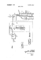
- FIG. 1 is a schematic view of one embodiment of an apparatus according to thisinvention
- FIG. 2 is a similar view of a modification of this apparatus
- FIG. 3 shows still another embodiment
- FIG. 4 shows a modification of this embodiment
- FIG. 5 is a graph illustrating the results of a series of tests.
- FIG. 6 to 11 are graphs illustrating the relationship of the melt viscosity and solution viscosity of certain test resins.
- the apparatus is shown to comprise a measuring cell I mounted in, and surrounded by, an immersion tube 2, both of which are immersed in the liquid in reaction vessel 3.
- the tube 2 has a plurality of vertically spaced ports 4 so that a certain amount of the liquid may flow through the tube, which serves to prevent excessive turbulences that may be caused by a stirrer in the reaction vessel in the vicinity of capillary 6.
- the measuring cell defines a measuring chamber 5 having a pre-determined volume, for instance cc, the upper end of the measuring chamber being delimited by the end of conduit 7 and the lower end of the measuring chamber leading into a capillary tube '6.
- a compensation tube 10 is also mounted in the measuring cell 1 to compensate for variations in the pressure and liquid level in reaction vessel 3, in a manner to be also described hereinafter.
- the viscosity measuring apparatus may be used under different pressure conditions, for which purpose the outlet 0 of valve'l4, the outlet 2 of valve 9 and the outlet 15 of vessel 11 may be connected to the space above the liquid level in reaction vessel 3.
- the measuring result i.e. the time required to press the liquid out of the measuring chamber of cell 1, is independent on the immersion depth of the cell in the liquid and the pressure over the surface of the liquid in the reaction vessel.
- the apparatus operates in the following manner:
- valve 9 When the apparatus is switched on, gates 1 and 2 of valve 9 are brought into communication and a time relay connected to valve 9 is actuated.
- the time relay is adjustable to determine the very short delay in which the solenoid valve 14, which is also connected to the relay, is switched over from position 1-0 to the position wherein the gates 1 and 2 are in communication.
- the gas pressure in conduits 7,8 and in measuring cell 1 is discharged through open gate 2 of valve 9.
- the measuring cell 1 is filled with the liquid from the reaction vessel whose viscosity is to be measured.
- a flow of about 50 to 100 liters per hour of inert gas passes through adjustable valve 22 and rotameter 19 into tube l8 which is adjustably positioned in vessel 13, whence the gas flows out through conduit 12 into compensation tube which vents the gas into the liquid in reaction vessel 3. Since, during the filling period of the measuring cell, the gates 1 and 2 of valve 9 are in communication while the valve gate 0 is blocked, no gas will pass through the valve 9 from conduit which branches off tube 18.
- the vessel 13 is closed on'top, the vessel being partially filled with an electrically conductive liquid, for instance a 1 percent KOH solution in a mixture of water and glycol, and the pressure p in the vessel above the liquid level beingequal to the sum of the hydrostatic pressure of column h extending from the outlet ends of the compensation tube 10 and capillary 6 to the surface of the liquid in'the reaction vessel, and the pressure over the liquid level in the reaction vessel.
- the pressure in conduit 20 is, therefore, equal to the sum of p and the hydrostatic pressure p of column k extending from the outlet end of tube 18 to the surface of the conductive liquid in vessel 13.
- a pair of electrodes k and k are positioned in vessel 13, with electrode k extending into tube 18 to a point about an inch or so from the lower or outlet end of the tube.
- the conductive connection between electrodes k and k is interrupted.
- the inert gas flowing into the measuring chamber through conduit 8 can no longer escape through conduit 7. This causes a small over-pressure to develop in conduit 8 and to back up into branch conduit 21 leading from conduit 8 into vessel 11.
- Vessel 11 is also partially filled with an electrically conductive liquid, for instance the same as that in vessel 13, a pair of electrodes k and k being positioned in vessel 11, with the electrode k; being mounted in tube 21.
- an electrically conductive liquid for instance the same as that in vessel 13, a pair of electrodes k and k being positioned in vessel 11, with the electrode k; being mounted in tube 21.
- the overpressure in conduit 21 depresses the level of the electrically conductive liquid therein, the electrical connection between electrodes k, and k is interrupted as soon as the liquid level is below electrode k
- Electrodes k -k and k -k are connected to an amplifier which supplies the electrodes with a voltage, for instance an alternating voltage of a maximum of one volt. These electrodes produce electrical control signals for operating the solenoid valves, the time relay,
- conduit 7 When measuring chamber 5 has been filled with the liquid whose viscosity is to be measured, access to conduit 7 is thus blocked by the liquid, a slight overpressure develops in conduit 8 and conduit 21, the level of the electrically conductive liquid in vessel 11 is tion wherein gates 0 and l of valve 9 are in communica-' tion so that gas from conduit 20 may enter into conduit 7. In other words, the gas flow through the measuring cell is reversed, and the gas flowing from conduit 7 begins to press the liquid out of the measuring chamber 5 into capillary 6.
- the time recorder is switched on to register the time required to press the liquid out of measuring chamber 5.
- an adjustable time relay interrupts the electrical contact between electrodes k and k, for a few seconds. This is to prevent the two electrodes from coming into electrical contact due to the fact that the electrically conductive liquid in vessel 13 rises in tube 18 to the level of electrode k by the sudden temporary pressure drop in conduit 20 when the valve 9 is opened to communicate with conduit 20.
- the measuring cell is emptied under a gas pressure p,+p through capillary 6.
- the gas pressure flowing in through valve 22 and rotameter 19 at an hourly rate of about to 100 liters escapes through conduit 18, vessel 13, conduit 12 and compensation tube 10 into the reaction vessel 3. Consequently, any pressure variations occurring in the reaction vessel are compensated during measuring.
- valve 26 increases again the pressure in conduit 20 from p to p P2-
- the pressure differential sensitive switches 24 and 25 and the pressure balanced reducing valve 26 are commercially available pneumatic instruments.
- the pressure balanced reducing valve 26 has been eliminated and its function is taken over by the compensation tube by extending this tube sufficiently to increase the hydrostatic pressure in this tube by an amount equal to that of column h in FIG. 1.
- conduits and 12 are interconnected so that, during the period of time when the liquid whose viscosity is measured is pressed out of the measuring chamber, the pressure in conduits 20 and 12 is the same, i.e. p +p At the moment the gas can escape through capillary 6, because the measuring chamber is empty, the pressure in conduit 20 drops to P1, as a consequence of which switch actuates the control circuit to advance to the next cycle.
- the switching means for the control circuit has been replaced by two conductivity measuring devices 24a and 25a positioned in the measuring cell, these devices producing electrical control pulses in response to changes in conductivity from zero to a measurable value.
- the inert gas is supplied under a predetermined pressure by metering valve 16, and when the apparatus is out of operation, gates 0 and 1 of solenoid valve 14 are open so that the gas escapes through capillary 6 into the liquid in the reaction vessel.
- gates l and 2 of valve 14 are brought into communication, as a consequence of which the measuring cell is filled under the influence of the hydrostatic pressure difference between the outlets of the capillary 6 and the conduit 10a.
- the device When the liquid reaches the conductivity measuring device 24a, the device produces an electrical control pulse which starts the time recorder.
- the liquid level in measuring cell la reaches the conductive measuring device 25a, the device produces an electrical control pulse stopping the time recorder and actuating valve 14 by bringing gates l and 0 into communication, as a consequence of which the cell is emptied under the influence of the gas pressure.
- valve 14 is actuated so that gates 1 and 2 are brought into communication again. At that moment a new measuring cycle starts.
- FIG. 4 shows another modification of the apparatus. Also here the electrical pulses are produced by change of conductivity from zero to a measurable value and vice versa.
- the insert gas is supplied under a predetermined pressure by a reducing valve 16.
- gates l and 2 of the solenoid valve 14 are open so that the gas escapes through capillary 6 into the liquid in the reaction vessel.
- gates 0 and l are brought into communication, as a consequence of which the measuring cell is filled.
- the device produces an electrical pulse which actuates valve 14, as a consequence of which gates l and 2 are brought into communication and the time recorder is started.
- the gas pressure in the measuring cell which is in communication with the compensation tube presses the liquid in the measuring cell through the capillary.
- the liquid level in the measuring cell la reaches the conductivity measuring device 24a the device produces again an electrical pulse delay stopping the time recorder and actuating an adjustable time relay to start the measuring cycle again.
- conductivity measuring devices 24a and 25a may be replaced by capacity measuring devices operating in an equivalent manner.
- the capillary viscosimeter hereinabove described is arranged for use in vessels for chemical and physical processes and makes, moreover, measurements in series possible.
- the melt viscosity of a synthetic resin for instance, may be determined in seconds and at a temperature prevailing in the reaction vessel.
- the melt viscosity is the viscosity of the liquid reaction product at the elevated temperature prevailing during the polymerization or condensation reaction.
- a condition for the practical use of the apparatus in the preparation of synthetic resins, where the melt viscosity instead of the viscosity of the solution is measured, is the presence of a close relationship between the two forms.
- the final product must show as a rule a viscosity range which is mostly indicated as the viscosity of a solution of the product at low temperature. It has been found that, of each tested resin type, the melt viscosity isdecisive for the viscosity of the solution, as elucidated by the tests described below.
- FIGS. 6,7,8 and 9 also show the good reproducibility; an almost equal melt viscosity of the final products of one and the same resin type gives practiplied to the preparation of other products, such as phenolic resins, amino resins, vinyl resins, polyesters, polyurethane resins, acrylate resins, etc.
- the invention in addition to the examples already mentioned, can be used wherever it is of importance to measure the viscosity during the preparation of intermediate products and final products I directly in a reaction vessel, dilution vessel or evaporator.
- capillary viscosimeters Some important conditions for accurate and reproducible measurements of the viscosity in reaction vessels by means of so-called capillary viscosimeters include, first a careful control of the temperature of the liquid in the reaction vessel, the influence of the temperature of the liquid to be measured upon the melt viscosity being considerable, whereforethe deviation may maximally amount to i 15 C; in the second place, the the amount of liquid in the measuring cell to be measured must be constant for each measuring; in the third place, the pressure difference under which the measuring cell is emptied or filled must be, the same at each measuring; the hydrostatic pressure of the liquid column calculated from the bottom of the capillary up to the liquid surface and the pressure over the liquid surface in the reaction vessel are comprised by the total pressure with which the measuring cell is emptied or filled; in the fourth place, the dimensions of the measuring cell, capillary and pressure must be selected so that the How in the capillary during emptying or filling the measuring cell remains laminary; in the fifth place, the measuring result must be made
- An apparatus for measuring the viscosity of a liquid product in a vessel by measuring the flow time of a predetermined amount of said liquid product through a capillary comprising: v
- a measuring cell including a measuring chamber of constant volume, a capillary outflow tube in communication with the measuring chamber at the lower end thereof, and a space above the measuring chamber,
- conduit system between the gas supply and the measuring cell for circulating gas through the measuring cell, the conduit system including a first conduit opening into the space above the measuring chamber, a second conduit opening into the measuring chamber at the upper end thereof, and a third conduit opening adjacent to the capillary tube, v
- electrical control means for actuating s id flow reversing means
- a time recording means the control means switching on the time recording means and actuating the flow reversing means when the liquid blocks the second conduit, and switching off the time recording means in response to the gas pressure drop in the measuring cell at the moment theliquid has been fully pressed out of the measuring chamber throughthe capillary tube;
- the electrical control means comprises a switching means for switching on the time recording means, which includes a vessel containing an electrically conductive liquid and a pair of electrodes positioned therein at different levels, the vessel being in communication with the conduit system. and the level of the conductive liquid in a predetermined amount of said liquid product through said vessel being depressed under the increased pressure in the conduitsystem when the second conduit is blocked, and the depression of the level of the conductive liquid causing interruption of the electrical contact between the electrodes.
- the apparatus of claim 1 further comprising an immersion tube surrounding the measuring cell and at least partially immersed in the. liquid in the reaction vessel, the immersion tube extending beyond the capillary tube and having ports for circulating the liquid in the reaction vessel through the immersion tube.
- the electrical control means comprises a switching means for switching on the time recording means which consists of a pressure differential sensitive switch actuated by the pressure rise occurring in the conduit system when the second conduit is blocked.
- the apparatus ofclaim 1 comprising a pressure balanced reducing valve for pressing'out the liquid from the measuring chamber under a constant overpressure, and wherein the electrical control means comprises a switching means for switching off the time recording means which consists of a pressure differential sensitive switch actuated by the pressure drop occurring in the conduit system when the liquid has I been fully pressed out of the measuring chamber.
- An apparatus for measuring the viscosity of a liquid product in a vessel by measuring the flow time of a capillary comprising:
- a measuring cell including a capillary outflow tube at the lower end thereof, b. a supply of an inert gas under a predetermined pressure, c. a first conduit between the gas supply and the measuring cell which conduit has an outlet opening in the upper end of the measuring cell, d. a three-way valve in the first conduit e. a second conduit connected to ,said three-way valve which second conduit opens below the liquid level in the vessel beside the measuring cell at a level substantially above that of the capillary tube, f. two conductivity measuring devices at different levels in the measuring cell but both below the opening of the second conduit, and g.
- An apparatus for measuring the viscosity of a liquid product in a vessel by measuring the flow time of a predetermined amount of said liquid product through a capillary comprising:
- a measuring cell including a capillary outflow tube at the lower end thereof, b. a supply of an inert gas under a predetermined pressure, I g cja first conduit between the gas supply and the measuring cell .which conduit has an outlet opening in the'upper end of the measuring cell, I d. a three-way valve in the first conduit,
- a second conduit connected to said three-way valve which second conduit opens below the liquid I ferent levels in the measuring cell but both below the opening of the second conduit and v g, a time recording means, the electrical capacity measuring devices, respectively, switching on and off the. time recording means when the liquid which rises in the measuring cell successively reaches the electrical capacity measuring device at the lower level and at the higher level.
- An apparatus for measuring the viscosity of a liquid product in a vessel by measuring the flow time of a predetermined amount of said liquid product through a capillary comprising:
- a measuring cell including a capillary outflow tube at the lower end thereof,
- a supply conduit of an inert gas under a predetermined pressure having an outlet in the liquid in the vessel at a level substantially below that of the I capillary tube
- a measuring cell including a capillary outflow tube levelswitchihg Off the lime recording meahs when at the l w r d th f, the liquid being pressed out of the measuring cell b; a supply co d it f an i gas under a predetep 15 reaches said electrical capacity measuring device.
Landscapes
- Physics & Mathematics (AREA)
- Health & Medical Sciences (AREA)
- Life Sciences & Earth Sciences (AREA)
- Chemical & Material Sciences (AREA)
- Analytical Chemistry (AREA)
- Biochemistry (AREA)
- General Health & Medical Sciences (AREA)
- General Physics & Mathematics (AREA)
- Immunology (AREA)
- Pathology (AREA)
- Feeding, Discharge, Calcimining, Fusing, And Gas-Generation Devices (AREA)
- Investigating Or Analyzing Materials By The Use Of Electric Means (AREA)
- Measurement Of Levels Of Liquids Or Fluent Solid Materials (AREA)
Applications Claiming Priority (1)
| Application Number | Priority Date | Filing Date | Title |
|---|---|---|---|
| US2037470A | 1970-03-17 | 1970-03-17 |
Publications (1)
| Publication Number | Publication Date |
|---|---|
| US3680362A true US3680362A (en) | 1972-08-01 |
Family
ID=21798290
Family Applications (1)
| Application Number | Title | Priority Date | Filing Date |
|---|---|---|---|
| US20374A Expired - Lifetime US3680362A (en) | 1970-03-17 | 1970-03-17 | Viscosimeter |
Country Status (8)
| Country | Link |
|---|---|
| US (1) | US3680362A (enExample) |
| JP (1) | JPS5026105B1 (enExample) |
| DE (1) | DE2047908C3 (enExample) |
| FR (1) | FR2083831A5 (enExample) |
| GB (1) | GB1312690A (enExample) |
| NL (1) | NL142236B (enExample) |
| SE (1) | SE372627B (enExample) |
| ZA (1) | ZA708451B (enExample) |
Cited By (19)
| Publication number | Priority date | Publication date | Assignee | Title |
|---|---|---|---|---|
| US3782173A (en) * | 1971-06-03 | 1974-01-01 | Akzo Nv | Viscosimeter |
| EP0144106A1 (en) * | 1983-12-05 | 1985-06-12 | ENICHEM S.p.A. | Improved process for the production of polyphenyleneoxide |
| US4677845A (en) * | 1984-12-07 | 1987-07-07 | Ricoh Company, Ltd. | Device for detecting viscosity of liquid |
| US6019735A (en) * | 1997-08-28 | 2000-02-01 | Visco Technologies, Inc. | Viscosity measuring apparatus and method of use |
| US6322525B1 (en) | 1997-08-28 | 2001-11-27 | Visco Technologies, Inc. | Method of analyzing data from a circulating blood viscometer for determining absolute and effective blood viscosity |
| US6322524B1 (en) | 1997-08-28 | 2001-11-27 | Visco Technologies, Inc. | Dual riser/single capillary viscometer |
| US20020040196A1 (en) * | 1997-08-28 | 2002-04-04 | Kenneth Kensey | Dual riser/single capillary viscometer |
| US6412336B2 (en) | 2000-03-29 | 2002-07-02 | Rheologics, Inc. | Single riser/single capillary blood viscometer using mass detection or column height detection |
| US6428488B1 (en) | 1997-08-28 | 2002-08-06 | Kenneth Kensey | Dual riser/dual capillary viscometer for newtonian and non-newtonian fluids |
| US6450974B1 (en) | 1997-08-28 | 2002-09-17 | Rheologics, Inc. | Method of isolating surface tension and yield stress in viscosity measurements |
| US6484566B1 (en) | 2000-05-18 | 2002-11-26 | Rheologics, Inc. | Electrorheological and magnetorheological fluid scanning rheometer |
| US6484565B2 (en) | 1999-11-12 | 2002-11-26 | Drexel University | Single riser/single capillary viscometer using mass detection or column height detection |
| US20030158500A1 (en) * | 1999-11-12 | 2003-08-21 | Kenneth Kensey | Decreasing pressure differential viscometer |
| US20040141183A1 (en) * | 2003-01-14 | 2004-07-22 | Larson David C. | Method and apparatus for measuring fluid viscosity using electric conductance |
| US20060065044A1 (en) * | 2004-09-28 | 2006-03-30 | Phasepsl Instrument Inc. | Viscometer |
| CN102192865A (zh) * | 2011-05-25 | 2011-09-21 | 东华大学 | 一种具有惰性气体保护的粘度测试装置及方法 |
| WO2017046623A1 (en) * | 2015-09-18 | 2017-03-23 | Total Sa | Method for analysing liquid samples |
| EP3193157A1 (fr) * | 2016-01-18 | 2017-07-19 | S.P.C.M. Sa | Dispositif de mesure de viscosite sous atmosphere inerte |
| US20230384287A1 (en) * | 2022-05-24 | 2023-11-30 | Canon Medical Systems Corporation | Analysis apparatus, analysis method, and storage medium |
Families Citing this family (1)
| Publication number | Priority date | Publication date | Assignee | Title |
|---|---|---|---|---|
| JPS62133053A (ja) * | 1985-12-03 | 1987-06-16 | Kobe Steel Ltd | チタン合金圧延板の熱処理方法 |
Citations (5)
| Publication number | Priority date | Publication date | Assignee | Title |
|---|---|---|---|---|
| SU121595A1 (ru) * | 1958-10-13 | 1958-11-30 | В.Я. Дьяченко | Капилл рный вискозиметр |
| US3071961A (en) * | 1959-12-22 | 1963-01-08 | Exxon Research Engineering Co | Automatic viscometer and process of using same |
| US3242720A (en) * | 1963-09-30 | 1966-03-29 | Phillips Petroleum Co | Apparatus for determining rheological properties |
| FR1566139A (enExample) * | 1968-05-30 | 1969-05-02 | ||
| US3540264A (en) * | 1967-04-24 | 1970-11-17 | Rhodiaceta | Automatic viscometer |
-
1970
- 1970-03-17 US US20374A patent/US3680362A/en not_active Expired - Lifetime
- 1970-05-23 JP JP45043951A patent/JPS5026105B1/ja active Pending
- 1970-06-12 NL NL707008593A patent/NL142236B/xx unknown
- 1970-08-11 SE SE7010961A patent/SE372627B/xx unknown
- 1970-09-29 DE DE2047908A patent/DE2047908C3/de not_active Expired
- 1970-12-10 GB GB5874270A patent/GB1312690A/en not_active Expired
- 1970-12-11 FR FR7044691A patent/FR2083831A5/fr not_active Expired
- 1970-12-14 ZA ZA708451A patent/ZA708451B/xx unknown
Patent Citations (5)
| Publication number | Priority date | Publication date | Assignee | Title |
|---|---|---|---|---|
| SU121595A1 (ru) * | 1958-10-13 | 1958-11-30 | В.Я. Дьяченко | Капилл рный вискозиметр |
| US3071961A (en) * | 1959-12-22 | 1963-01-08 | Exxon Research Engineering Co | Automatic viscometer and process of using same |
| US3242720A (en) * | 1963-09-30 | 1966-03-29 | Phillips Petroleum Co | Apparatus for determining rheological properties |
| US3540264A (en) * | 1967-04-24 | 1970-11-17 | Rhodiaceta | Automatic viscometer |
| FR1566139A (enExample) * | 1968-05-30 | 1969-05-02 |
Cited By (39)
| Publication number | Priority date | Publication date | Assignee | Title |
|---|---|---|---|---|
| US3782173A (en) * | 1971-06-03 | 1974-01-01 | Akzo Nv | Viscosimeter |
| EP0144106A1 (en) * | 1983-12-05 | 1985-06-12 | ENICHEM S.p.A. | Improved process for the production of polyphenyleneoxide |
| US4677845A (en) * | 1984-12-07 | 1987-07-07 | Ricoh Company, Ltd. | Device for detecting viscosity of liquid |
| US20040194538A1 (en) * | 1997-08-28 | 2004-10-07 | Rheologics, Inc. | Dual riser/single capillary viscometer |
| US6077234A (en) * | 1997-08-28 | 2000-06-20 | Visco Technologies, Inc. | In-vivo apparatus and method of use for determining the effects of materials, conditions, activities, and lifestyles on blood parameters |
| US6152888A (en) * | 1997-08-28 | 2000-11-28 | Visco Technologies, Inc. | Viscosity measuring apparatus and method of use |
| US6193667B1 (en) | 1997-08-28 | 2001-02-27 | Visco Technologies, Inc. | Methods of determining the effect(s) of materials, conditions, activities and lifestyles |
| US6200277B1 (en) | 1997-08-28 | 2001-03-13 | Visco Technologies, Inc. | In-vivo apparatus and methods of use for determining the effects of materials, conditions, activities, and lifestyles on blood parameters |
| US6261244B1 (en) | 1997-08-28 | 2001-07-17 | Visco Technologies, Inc. | Viscosity measuring apparatus and method of use |
| US6322525B1 (en) | 1997-08-28 | 2001-11-27 | Visco Technologies, Inc. | Method of analyzing data from a circulating blood viscometer for determining absolute and effective blood viscosity |
| US6322524B1 (en) | 1997-08-28 | 2001-11-27 | Visco Technologies, Inc. | Dual riser/single capillary viscometer |
| US20020040196A1 (en) * | 1997-08-28 | 2002-04-04 | Kenneth Kensey | Dual riser/single capillary viscometer |
| US6402703B1 (en) | 1997-08-28 | 2002-06-11 | Visco Technologies, Inc. | Dual riser/single capillary viscometer |
| US6907772B2 (en) | 1997-08-28 | 2005-06-21 | Rheologics, Inc. | Dual riser/single capillary viscometer |
| US6428488B1 (en) | 1997-08-28 | 2002-08-06 | Kenneth Kensey | Dual riser/dual capillary viscometer for newtonian and non-newtonian fluids |
| US6450974B1 (en) | 1997-08-28 | 2002-09-17 | Rheologics, Inc. | Method of isolating surface tension and yield stress in viscosity measurements |
| US6805674B2 (en) | 1997-08-28 | 2004-10-19 | Rheologics, Inc. | Viscosity measuring apparatus and method of use |
| US6019735A (en) * | 1997-08-28 | 2000-02-01 | Visco Technologies, Inc. | Viscosity measuring apparatus and method of use |
| US6745615B2 (en) | 1997-08-28 | 2004-06-08 | Rheologics, Inc. | Dual riser/single capillary viscometer |
| US6624435B2 (en) | 1997-08-28 | 2003-09-23 | Rheologics, Inc. | Dual riser/dual capillary viscometer for newtonian and non-newtonian fluids |
| US6484565B2 (en) | 1999-11-12 | 2002-11-26 | Drexel University | Single riser/single capillary viscometer using mass detection or column height detection |
| US20030158500A1 (en) * | 1999-11-12 | 2003-08-21 | Kenneth Kensey | Decreasing pressure differential viscometer |
| US6571608B2 (en) | 1999-11-12 | 2003-06-03 | Rheologics, Inc. | Single riser/single capillary viscometer using mass detection or column height detection |
| US6412336B2 (en) | 2000-03-29 | 2002-07-02 | Rheologics, Inc. | Single riser/single capillary blood viscometer using mass detection or column height detection |
| US6564618B2 (en) | 2000-05-18 | 2003-05-20 | Rheologics, Inc. | Electrorheological and magnetorheological fluid scanning rheometer |
| US6484566B1 (en) | 2000-05-18 | 2002-11-26 | Rheologics, Inc. | Electrorheological and magnetorheological fluid scanning rheometer |
| US6732573B2 (en) | 2000-05-18 | 2004-05-11 | Rheologics, Inc. | Single riser/single capillary blood viscometer using mass detection or column height detection |
| US6598465B2 (en) | 2000-05-18 | 2003-07-29 | Rheologics, Inc. | Electrorheological and magnetorheological fluid scanning rheometer |
| US6796168B1 (en) | 2000-08-28 | 2004-09-28 | Rheologics, Inc. | Method for determining a characteristic viscosity-shear rate relationship for a fluid |
| US20040141183A1 (en) * | 2003-01-14 | 2004-07-22 | Larson David C. | Method and apparatus for measuring fluid viscosity using electric conductance |
| US7190639B2 (en) * | 2003-01-14 | 2007-03-13 | Larson David C | Method and apparatus for measuring fluid viscosity using electric conductance |
| US7131318B2 (en) * | 2004-09-28 | 2006-11-07 | Phase Psl Instrument Inc. | Viscometer |
| US20060065044A1 (en) * | 2004-09-28 | 2006-03-30 | Phasepsl Instrument Inc. | Viscometer |
| CN102192865A (zh) * | 2011-05-25 | 2011-09-21 | 东华大学 | 一种具有惰性气体保护的粘度测试装置及方法 |
| CN102192865B (zh) * | 2011-05-25 | 2013-05-08 | 东华大学 | 一种具有惰性气体保护的粘度测试装置及方法 |
| WO2017046623A1 (en) * | 2015-09-18 | 2017-03-23 | Total Sa | Method for analysing liquid samples |
| EP3193157A1 (fr) * | 2016-01-18 | 2017-07-19 | S.P.C.M. Sa | Dispositif de mesure de viscosite sous atmosphere inerte |
| FR3046843A1 (fr) * | 2016-01-18 | 2017-07-21 | Snf Sas | Dispositif de mesure de viscosite sous atsmosphere inerte |
| US20230384287A1 (en) * | 2022-05-24 | 2023-11-30 | Canon Medical Systems Corporation | Analysis apparatus, analysis method, and storage medium |
Also Published As
| Publication number | Publication date |
|---|---|
| GB1312690A (en) | 1973-04-04 |
| DE2047908C3 (de) | 1974-02-14 |
| NL7008593A (enExample) | 1971-09-21 |
| FR2083831A5 (enExample) | 1971-12-17 |
| NL142236B (nl) | 1974-05-15 |
| DE2047908B2 (de) | 1973-07-12 |
| DE2047908A1 (de) | 1971-09-30 |
| SE372627B (enExample) | 1974-12-23 |
| JPS5026105B1 (enExample) | 1975-08-28 |
| ZA708451B (en) | 1971-09-29 |
Similar Documents
| Publication | Publication Date | Title |
|---|---|---|
| US3680362A (en) | Viscosimeter | |
| US2752776A (en) | Apparatus for determining flash point | |
| US5509294A (en) | Apparatus for determining amount of gases dissolved in liquids | |
| US5365776A (en) | Process and device for determining the viscosity of liquids | |
| US2977199A (en) | Method for the continuous testing of flowing materials | |
| US2211606A (en) | Liquid level indicator | |
| US3782173A (en) | Viscosimeter | |
| US3520179A (en) | Variable head rheometer for measuring non-newtonian fluids | |
| US2696734A (en) | Viscometer for semifluid substances | |
| US3221541A (en) | Method of and apparatus for accurately and instantaneously determining the ratio of the constituents of a vapor-liquid-solid mixture or a mixture of any two of the components thereof | |
| US4681601A (en) | Bubble injection dissolved gas measurement method and apparatus | |
| CA2264855A1 (en) | Method for analyzing a sample of a starch-containing product and a device for such analyses | |
| US3930402A (en) | Viscosimeter | |
| US3685346A (en) | Direct reading quantitative gas measuring device | |
| US2836975A (en) | Disposable viscosity cup | |
| Blair et al. | A simple method for detecting an early stage in coagulation of rennetted milk | |
| Bikerman | A Penetroviscometer for very viscous liquids | |
| US4604263A (en) | Cell for gas sample equilibrator | |
| US4264328A (en) | Method for recording measured values in an automatically performed blood gas analysis | |
| US2741911A (en) | Gas concentration measurement | |
| US3191428A (en) | Vapor pressure measuring apparatus | |
| US3780565A (en) | Fluid vaporization tester | |
| US1945822A (en) | Method and apparatus for measuring viscosity | |
| US365120A (en) | de layal | |
| US3033040A (en) | Density measuring apparatus |