US367367A - Ezekibl l - Google Patents
Ezekibl l Download PDFInfo
- Publication number
- US367367A US367367A US367367DA US367367A US 367367 A US367367 A US 367367A US 367367D A US367367D A US 367367DA US 367367 A US367367 A US 367367A
- Authority
- US
- United States
- Prior art keywords
- gate
- rod
- rods
- irons
- wheel
- Prior art date
- Legal status (The legal status is an assumption and is not a legal conclusion. Google has not performed a legal analysis and makes no representation as to the accuracy of the status listed.)
- Expired - Lifetime
Links
- 235000000396 iron Nutrition 0.000 description 3
- XEEYBQQBJWHFJM-UHFFFAOYSA-N Iron Chemical compound [Fe] XEEYBQQBJWHFJM-UHFFFAOYSA-N 0.000 description 2
- 239000000463 material Substances 0.000 description 2
- 102000012152 Securin Human genes 0.000 description 1
- 108010061477 Securin Proteins 0.000 description 1
- 238000010276 construction Methods 0.000 description 1
- 229910052742 iron Inorganic materials 0.000 description 1
Images
Classifications
-
- E—FIXED CONSTRUCTIONS
- E05—LOCKS; KEYS; WINDOW OR DOOR FITTINGS; SAFES
- E05F—DEVICES FOR MOVING WINGS INTO OPEN OR CLOSED POSITION; CHECKS FOR WINGS; WING FITTINGS NOT OTHERWISE PROVIDED FOR, CONCERNED WITH THE FUNCTIONING OF THE WING
- E05F13/00—Mechanisms operated by the movement or weight of a person or vehicle
- E05F13/04—Mechanisms operated by the movement or weight of a person or vehicle by platforms lowered by the weight of the user
Definitions
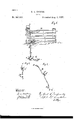
- My invention relates to improvements in folding gates, the object of which is to provide a cheap, simple, durable, and convenient device to serve as a folding gate, and one that may be opened or closed without dismounting from a vehicle.
- Said rods b are preferably provided with openings in their ends, and are all made of the same length, and are of 'any desired number, according to the height of gate
- the rods are held in place by being secured at their front ends to a cross-piece or plate, 0.
- Said plate may be of any suitable material, preferably of iron, and is provided with bolts I) for entering the openings in rods b and securin'g them thereto, and also to serve as hinges for the rods 1) to Work upon as the gate is folded up or let down, as may be desired.
- the back ends of rods 5 are preferably secured to a plate, 0 but may be secured to the post A by-means of bolts b, which are to serve as hinges for the back ends of rods 12.
- the rods b are all made of the same length; but the back end of the lower rod is placed close to the front edge of the post or plate at the back of the gate and of the cross-piece at the front of the gate.
- the top rod is placed farther back on the post at the back of the gate and on the cross-piece at the front of the gate than thelower rod, and the other rods are placed on a diagonal line between the lower rod and the top rod, so that when the gate is folded up it will be perpendicular and the rods. be side by side.
- ' D is a trip-rod, and is provided with a loop
- Triprod D is provided with an offset, LP, in its middle, which is placed at right angles with the lower end of loops cl in the ends of the triprod D.
- Said offset (1 is provided with aring, d for receiving the bottom rod of the gate, which is made to work easily back and forth upon said rod, and is for the purpose of pushing the gate up and drawing it down.
- Said trip-rod is secured in place by any suitable means.
- E E are wheel-irons, and are provided with two offsets, e 6 in each rod.
- Said offsets are placed at right angles with each other.
- the ends 6 c are parallel with the offsets e in the wheel-irons E E, so that when the gate is closed the ends 6 e and the set-offs e will be in an upright position and the setoffs 0 will lie on the ground.
- These irons are secured in place by any suitable means, and are placed across the driveway each side of the gate.
- My invention is operated by driving the front wheel of the vehicle over one of the set offs, c and by so doing the ends 0 e of the wheel-irons E E will press downward and'backward on the back side of loops d and draw the offset 03 to an upright position.
- the offset pushes upward on the lower rod of the gate and folds the gate.
- the wheel of the vehicle is made torun over one of the opposite offsets, 0 which was turned upright by the opening of the gate, thus drawing for ward on the frontsideofloop d, throwing down the set-offd in trip-rod D, and closing the gate.
Landscapes
- Refuge Islands, Traffic Blockers, Or Guard Fence (AREA)
Description
E. L. COOPER.
(Mo dew GATE.
Patented Aug. 2, 1887.-
MHEWESEBS.
UNITED STATES PATENT OFFICE.
EZEKIEL'L. COOPER, OF CLARENCE, MISSOURI.
GATE.
SPECIFICATION forming part of Letters Patent No. 367,367, dated August 2, 188'7.
Application filed November 30, 1886. Serial No. 220,321.
(ModcL) To all whom it may concern:
Be itknown that I, EZEKIEL L. COOPER, a.
. citizen of the United States, residing atClarence, in the county of Shelby and State of Missouri, have invented certain new and useful Improvements in Gates; and I do hereby de clare the following to be a full, clear, and exact description-of the invention, such as will enable others skilled in the art to which it appertains to make and use the same. I
My invention relates to improvements in folding gates, the object of which is to provide a cheap, simple, durable, and convenient device to serve as a folding gate, and one that may be opened or closed without dismounting from a vehicle. These objects I attain by means of the device illustrated in the accompanying drawings, forming a part of this specib, to serve as rails; but any suitable material desired.
may be used. Said rods b are preferably provided with openings in their ends, and are all made of the same length, and are of 'any desired number, according to the height of gate The rods are held in place by being secured at their front ends to a cross-piece or plate, 0. Said plate may be of any suitable material, preferably of iron, and is provided with bolts I) for entering the openings in rods b and securin'g them thereto, and also to serve as hinges for the rods 1) to Work upon as the gate is folded up or let down, as may be desired. The back ends of rods 5 are preferably secured to a plate, 0 but may be secured to the post A by-means of bolts b, which are to serve as hinges for the back ends of rods 12. v
The rods b are all made of the same length; but the back end of the lower rod is placed close to the front edge of the post or plate at the back of the gate and of the cross-piece at the front of the gate. The top rod is placed farther back on the post at the back of the gate and on the cross-piece at the front of the gate than thelower rod, and the other rods are placed on a diagonal line between the lower rod and the top rod, so that when the gate is folded up it will be perpendicular and the rods. be side by side.
' D is a trip-rod, and is provided witha loop,
d, at each end in the shape of an arc ofa circle, which extends upward and backward from the rod .D, and is to receive the ends e e of the wheel-irons E E to operate the same. Triprod D is provided with an offset, LP, in its middle, which is placed at right angles with the lower end of loops cl in the ends of the triprod D. Said offset (1 is provided with aring, d for receiving the bottom rod of the gate, which is made to work easily back and forth upon said rod, and is for the purpose of pushing the gate up and drawing it down. Said trip-rod is secured in place by any suitable means. E E are wheel-irons, and are provided with two offsets, e 6 in each rod. Said offsets are placed at right angles with each other. The ends 6 c are parallel with the offsets e in the wheel-irons E E, so that when the gate is closed the ends 6 e and the set-offs e will be in an upright position and the setoffs 0 will lie on the ground. These irons are secured in place by any suitable means, and are placed across the driveway each side of the gate.
My invention is operated by driving the front wheel of the vehicle over one of the set offs, c and by so doing the ends 0 e of the wheel-irons E E will press downward and'backward on the back side of loops d and draw the offset 03 to an upright position. The offset pushes upward on the lower rod of the gate and folds the gate. To close the gate, the wheel of the vehicle is made torun over one of the opposite offsets, 0 which was turned upright by the opening of the gate, thus drawing for ward on the frontsideofloop d, throwing down the set-offd in trip-rod D, and closing the gate.
I amaware of the construct-ion shown in Letters Patent Nos. 248, 807 and 218,826, and make no claim thereto.
Having thus described my invention, what I claim as new, and desire to secure by Letters Patent, is-- 1. The combination, with a vertically-foldat its ends to engage arms 0 e of the wheeling gate, of a trip-rod, D, having an offset in irons, and with an offset in its middle conthe middle connecting it to the gate, and areneeted by a ring to the lower bar of the gate, shaped loops at its ends, which engage wheelall substantially as shown and described.
5 irons E E, all substantially as shown and de- In testimony whereof Ial'fixmysignatnrein 15 scribed. presence of two witnesses.
2. The combination, with a vertically-fold- EZEKIEL L. COOPER. ing gate, constructed as shown, of double- Witnesses: cranked wheel-irons E E, having arms 0 e, R. H. JONES,
To and a trip rod provided with arc-shaped loops \V. O. FROST.
Publications (1)
| Publication Number | Publication Date |
|---|---|
| US367367A true US367367A (en) | 1887-08-02 |
Family
ID=2436385
Family Applications (1)
| Application Number | Title | Priority Date | Filing Date |
|---|---|---|---|
| US367367D Expired - Lifetime US367367A (en) | Ezekibl l |
Country Status (1)
| Country | Link |
|---|---|
| US (1) | US367367A (en) |
Cited By (1)
| Publication number | Priority date | Publication date | Assignee | Title |
|---|---|---|---|---|
| US3052485A (en) * | 1959-09-21 | 1962-09-04 | George M Clarkson | Impact gate |
-
0
- US US367367D patent/US367367A/en not_active Expired - Lifetime
Cited By (1)
| Publication number | Priority date | Publication date | Assignee | Title |
|---|---|---|---|---|
| US3052485A (en) * | 1959-09-21 | 1962-09-04 | George M Clarkson | Impact gate |
Similar Documents
| Publication | Publication Date | Title |
|---|---|---|
| US367367A (en) | Ezekibl l | |
| US935206A (en) | Gate. | |
| US428905A (en) | auerra | |
| US398189A (en) | Jacob t | |
| US313226A (en) | Gboege caeey milgate | |
| US1292437A (en) | Gate. | |
| US296528A (en) | Gate opening and closing apparatus | |
| US1011569A (en) | Gate. | |
| US883471A (en) | Locking-bolt for guards to openings. | |
| US816188A (en) | Gate. | |
| US575942A (en) | chiloott | |
| US282026A (en) | Jonathan zook | |
| US194889A (en) | Improvement in gates | |
| US254058A (en) | Latch for sliding gates | |
| US737331A (en) | Gate. | |
| US541761A (en) | kinser | |
| US511635A (en) | Richard t | |
| US557584A (en) | johnson | |
| US269396A (en) | Milton durnell | |
| US355293A (en) | Joseph g | |
| US272646A (en) | chilcott | |
| US402998A (en) | st ong | |
| US473752A (en) | William huff | |
| US184430A (en) | Improvement in railroad-switches | |
| US1102691A (en) | Gate. |