US3663645A - Liquid quench - Google Patents
Liquid quench Download PDFInfo
- Publication number
- US3663645A US3663645A US7707A US3663645DA US3663645A US 3663645 A US3663645 A US 3663645A US 7707 A US7707 A US 7707A US 3663645D A US3663645D A US 3663645DA US 3663645 A US3663645 A US 3663645A
- Authority
- US
- United States
- Prior art keywords
- quenching
- fluid
- hydrocarbons
- conduit
- stream
- Prior art date
- Legal status (The legal status is an assumption and is not a legal conclusion. Google has not performed a legal analysis and makes no representation as to the accuracy of the status listed.)
- Expired - Lifetime
Links
- 238000010791 quenching Methods 0.000 title abstract description 107
- 239000007788 liquid Substances 0.000 title description 26
- 230000000171 quenching effect Effects 0.000 abstract description 79
- 229930195733 hydrocarbon Natural products 0.000 abstract description 28
- 150000002430 hydrocarbons Chemical class 0.000 abstract description 28
- 238000000034 method Methods 0.000 abstract description 28
- 239000007789 gas Substances 0.000 abstract description 16
- 239000012530 fluid Substances 0.000 description 69
- 238000006243 chemical reaction Methods 0.000 description 16
- 239000007921 spray Substances 0.000 description 15
- 238000002347 injection Methods 0.000 description 12
- 239000007924 injection Substances 0.000 description 12
- 238000011144 upstream manufacturing Methods 0.000 description 10
- VGGSQFUCUMXWEO-UHFFFAOYSA-N Ethene Chemical compound C=C VGGSQFUCUMXWEO-UHFFFAOYSA-N 0.000 description 9
- 239000005977 Ethylene Substances 0.000 description 9
- 238000000197 pyrolysis Methods 0.000 description 6
- 239000007795 chemical reaction product Substances 0.000 description 5
- 239000000571 coke Substances 0.000 description 5
- 238000010276 construction Methods 0.000 description 5
- 238000004519 manufacturing process Methods 0.000 description 5
- 230000015572 biosynthetic process Effects 0.000 description 4
- 238000009835 boiling Methods 0.000 description 4
- 230000000694 effects Effects 0.000 description 4
- 230000005484 gravity Effects 0.000 description 3
- 239000000203 mixture Substances 0.000 description 3
- 239000000047 product Substances 0.000 description 3
- 239000011269 tar Substances 0.000 description 3
- 239000006227 byproduct Substances 0.000 description 2
- 239000000110 cooling liquid Substances 0.000 description 2
- 230000007423 decrease Effects 0.000 description 2
- 238000011084 recovery Methods 0.000 description 2
- 230000009467 reduction Effects 0.000 description 2
- 238000010517 secondary reaction Methods 0.000 description 2
- 230000009471 action Effects 0.000 description 1
- 238000004458 analytical method Methods 0.000 description 1
- 238000013459 approach Methods 0.000 description 1
- 238000001311 chemical methods and process Methods 0.000 description 1
- 239000000356 contaminant Substances 0.000 description 1
- 230000007812 deficiency Effects 0.000 description 1
- 238000010438 heat treatment Methods 0.000 description 1
- 230000013011 mating Effects 0.000 description 1
- 238000002156 mixing Methods 0.000 description 1
- 238000012986 modification Methods 0.000 description 1
- 230000004048 modification Effects 0.000 description 1
- 210000002445 nipple Anatomy 0.000 description 1
- 229920000642 polymer Polymers 0.000 description 1
- 238000006116 polymerization reaction Methods 0.000 description 1
- 238000005381 potential energy Methods 0.000 description 1
- 230000008569 process Effects 0.000 description 1
- 230000003134 recirculating effect Effects 0.000 description 1
- 238000009834 vaporization Methods 0.000 description 1
- 230000008016 vaporization Effects 0.000 description 1
Images

Classifications
-
- B—PERFORMING OPERATIONS; TRANSPORTING
- B01—PHYSICAL OR CHEMICAL PROCESSES OR APPARATUS IN GENERAL
- B01D—SEPARATION
- B01D51/00—Auxiliary pretreatment of gases or vapours to be cleaned
- B01D51/10—Conditioning the gas to be cleaned
-
- C—CHEMISTRY; METALLURGY
- C10—PETROLEUM, GAS OR COKE INDUSTRIES; TECHNICAL GASES CONTAINING CARBON MONOXIDE; FUELS; LUBRICANTS; PEAT
- C10G—CRACKING HYDROCARBON OILS; PRODUCTION OF LIQUID HYDROCARBON MIXTURES, e.g. BY DESTRUCTIVE HYDROGENATION, OLIGOMERISATION, POLYMERISATION; RECOVERY OF HYDROCARBON OILS FROM OIL-SHALE, OIL-SAND, OR GASES; REFINING MIXTURES MAINLY CONSISTING OF HYDROCARBONS; REFORMING OF NAPHTHA; MINERAL WAXES
- C10G9/00—Thermal non-catalytic cracking, in the absence of hydrogen, of hydrocarbon oils
- C10G9/002—Cooling of cracked gases
-
- F—MECHANICAL ENGINEERING; LIGHTING; HEATING; WEAPONS; BLASTING
- F28—HEAT EXCHANGE IN GENERAL
- F28C—HEAT-EXCHANGE APPARATUS, NOT PROVIDED FOR IN ANOTHER SUBCLASS, IN WHICH THE HEAT-EXCHANGE MEDIA COME INTO DIRECT CONTACT WITHOUT CHEMICAL INTERACTION
- F28C3/00—Other direct-contact heat-exchange apparatus
- F28C3/06—Other direct-contact heat-exchange apparatus the heat-exchange media being a liquid and a gas or vapour
-
- Y—GENERAL TAGGING OF NEW TECHNOLOGICAL DEVELOPMENTS; GENERAL TAGGING OF CROSS-SECTIONAL TECHNOLOGIES SPANNING OVER SEVERAL SECTIONS OF THE IPC; TECHNICAL SUBJECTS COVERED BY FORMER USPC CROSS-REFERENCE ART COLLECTIONS [XRACs] AND DIGESTS
- Y10—TECHNICAL SUBJECTS COVERED BY FORMER USPC
- Y10S—TECHNICAL SUBJECTS COVERED BY FORMER USPC CROSS-REFERENCE ART COLLECTIONS [XRACs] AND DIGESTS
- Y10S261/00—Gas and liquid contact apparatus
- Y10S261/54—Venturi scrubbers
-
- Y—GENERAL TAGGING OF NEW TECHNOLOGICAL DEVELOPMENTS; GENERAL TAGGING OF CROSS-SECTIONAL TECHNOLOGIES SPANNING OVER SEVERAL SECTIONS OF THE IPC; TECHNICAL SUBJECTS COVERED BY FORMER USPC CROSS-REFERENCE ART COLLECTIONS [XRACs] AND DIGESTS
- Y10—TECHNICAL SUBJECTS COVERED BY FORMER USPC
- Y10S—TECHNICAL SUBJECTS COVERED BY FORMER USPC CROSS-REFERENCE ART COLLECTIONS [XRACs] AND DIGESTS
- Y10S585/00—Chemistry of hydrocarbon compounds
- Y10S585/909—Heat considerations
- Y10S585/911—Heat considerations introducing, maintaining, or removing heat by atypical procedure
-
- Y—GENERAL TAGGING OF NEW TECHNOLOGICAL DEVELOPMENTS; GENERAL TAGGING OF CROSS-SECTIONAL TECHNOLOGIES SPANNING OVER SEVERAL SECTIONS OF THE IPC; TECHNICAL SUBJECTS COVERED BY FORMER USPC CROSS-REFERENCE ART COLLECTIONS [XRACs] AND DIGESTS
- Y10—TECHNICAL SUBJECTS COVERED BY FORMER USPC
- Y10S—TECHNICAL SUBJECTS COVERED BY FORMER USPC CROSS-REFERENCE ART COLLECTIONS [XRACs] AND DIGESTS
- Y10S585/00—Chemistry of hydrocarbon compounds
- Y10S585/919—Apparatus considerations
- Y10S585/921—Apparatus considerations using recited apparatus structure
- Y10S585/924—Reactor shape or disposition
Definitions
- the latter In the immediate vicinity of the outlet connecting the reactor with the conduit the latter is provided with a long radius bend of at least approximately $5 to facilitate the injection of cooling liquid concurrently and coaxially into the stream of hot gaseous hydrocarbons without o'bstruction of the flow path for the hot gaseous hydrocarbons, in order to avoid any flow disturbance of the stream of hot gaseous hydrocarbons passing through the conduit.
- the conduit Downstream of this bend the conduit diverges to constitute a diffusor.
- the bend is associated with at least one fluid-injecting nozzle which injects the cooling liquid, such as recycled or recirculated hydrocarbons, into the outlet portion of the bend.
- the present invention relates generally to the quenching of hot fluids, and more particularly to the quenching of heated hydrocarbons. Still more particularly the invention relates to a method of quenching heated hydrocarbons and to an apparatus for carrying the method into effect.
- a further, and perhaps the most significant deficiency of the prior art devices is the formation of coke, polymer or similar deposits if the devices are operated at temperatures facilitating the recovery of the quenched heat by generation of steam in a quench cooler.
- the quench medium-when separated from the gaseout reactor efiluenttoo cold renders the quench medium-when separated from the gaseout reactor efiluenttoo cold to facilitate economical use of the quenched heat.
- a concomitant object of the invention is to provide for quick and intimate quenching of the reactor efiluent without producing a significant pressure drop of the reaction product in the quenching device.
- Still a further object of the invention is to provide a method of quenching with the aforementioned advantages in mind, and which additionally will result in an increased yield of the desired reaction product, such as ethylene obtained by pyrolysis of low molecular weight hydrocarbons.
- a still further object of the invention is to provides such a quenching method which will permit quenching of the reactor effiuents at higher temperatures of such an order as to facilitate heat recovery from the quench fluid, without substantial formation of coke or similar deposits.
- Yet an additional object of the invention is to provide an apparatus for carrying the novel method into effect.
- one feature of the invention resides in a method of quenching hot fluid, such as heated hydrocarbons, which method briefly stated comprises the steps of conveying a stream of hot fluid in a predetemined enclosed path from an upstream end of an inlet region through an expansion region and to an end of the latter downstream of the expansion region.
- Quench fluid is injected into the stream of hot fluid in the expansion region coaxially and concurrently with the stream, the quench fluid being cooler than the hot fluid and which could, for instance, be constituted by liquid recirculated hydrocarbons if the hot fluid is constituted by heated by drocarbons.
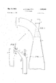
- FIG. 1 is a diagrammatic illustration showing an apparatus according to the present invention
- FIG. 2 is a diagrammatic view similar to FIG. 1, but illustrating a further embodiment of the invention.
- FIG. 3 is a detail view, partly in longitudinal section and on an enlarged scale, of an injection nozzle for use in the apparatus of FIGS. 1 and 2.
- a reactor of any known construction suitable for the purposes at hand such as the pyrolysis of hydrocarbons, is provided internally with a reaction zone 1. While most such reactors are tubular coils, other constructions which may be suitable should be understood as being included in the scope of this description.
- the outlet of the reaction zone 1 communicates with a conduit 3 which in turn communicates with a bent conduit portion 4.
- the latter defines an angle of approximately at least 45 and its downstream end merges with the upstream end of a conduit portion 5 which diverges so as to constitute an expansion zone.
- the angle of divergence is preferably between approximately 6 and
- the radius R of the bent conduit portion 4 is advantageously between 2 and 5 times the diameter d of the conduit portion 3.
- the manner in which the nozzle 8 injects the quenching fluid into the upstream end of the divergent conduit portion 5 is identified by the arrows and the angle of divergence of the conduit section is shown to be between substantially 6 and 30.
- the actual spray angle becomes smaller than the spray angle of the nozzle, which is determined in a stagnating environment.
- Quench oil injection velocity it./see 60 80-150 Quench oil temperature, F 350 250-500 Quench oil flow rates, lbs/hr- 60, 500 20, 000-400, 000
- the outlet of the reaction zone 1 again communicates with conduit means which comprises a plurality of sections as illustrated.
- the conduit 3 also communicates directly with the reactor outlet and should again be as short as possible.
- the conduit 3 is provided with or secured to a bent conduit portion 4 defining an angle of approximately 45 as before.
- the downstream end of the portion 4 in turn communicates with a relatively short circuit portion 5' which diverges in a downstream direction, that is in the direction away from the reaction zone 1, and which in turn is also providedin the region of its downstream end-with a bent portion 6 again defining an angle of approximately 45".
- the angle of divergence of the conduit portion 5, which latter of course again constitutes an expansion region, is preferably between approximately 6 and 30".
- a terminal conduit 7 is provided communicating with the downstream end of the bent portion 6 and having a constant or at least substantially constant cross-section for conveying the quenched and quenching fluids away.
- the first nozzle 8 in this embodiment communicates with the bent conduit portion 4 in the region of its upstream end, preferably at its juncture with the conduit 3.
- a pipeline 9 communicates with the noozle 8 and supplies the latter with quenching fluid, such as recycled liquid hydrocarbons which are a conventional byproduct of ethylene production as is well known to those skilled in the art.
- This quenching fluid is cool with reference to the temperature of the heated hydrocarbons issuing from the outlet of the reaction zone 1. It is injected by the nozzle 8 towards the outlet region of the bent portion 4 in concurrentdirection with the main flow of the heated hydrocarbons.
- bent portion 4 is to facilitate injection of the quneching fluid coaxially and concurrently with the hot gas stream without requiring obstructions in the flow path of the gas stream, thus avoiding flow disturbances and development of turbulence.
- a second nozzle 10 is provided with communicates with the bent conduit portion 6, again in the region of the upstream end of the portion 6 and at the outer side of the curvature.
- a supply pipe 11 communicates with the nozzle 10 and supplies thereto additional quenching fluid, that is additional recycled liquid hydrocarbons. This additional quenching fluid is injected b ythe nozzle 10 in concurrent direction into the partially quenched heated hydrocarbons.
- -35% of the quenching fluid are injected by nozzle 8 and the remainder required to make up 100% is injected by the nozzle 10. This makes it possible, in other words, to inject the larger part of the quenching fluid into the gas stream in a zone of lower gas velocity in order to reduce the pressure drop even more than with a single injection.
- the invention provides for essentially uniform heating of the quenching liquid by the reactor eflluent in the shortest possible time, without substantial parts of the quenching fluid being heated to temperatures higher than the final equilibrium temperature of the mixture consisting of reactor effluent and quenching fluid. This makes it possible to operate the quench system according to the present invention closely up to the temperature at which the quenched components, or the constitutent components of the quenching fluid, would become unstable and decompose.
- the injection of quenching fluid through the nozzle 8 takes place in both embodiments in form of a full cone spray with a velocity which is no lower than approximately half of the velocity of the liquid-vapor mixture at the downstream end of the conduit portion 5 or 5'.
- the width of the spray cone is so selected that the cross-section of the conduit portion 5 or 5 is rather completely covered with quenching fluid spray, but that the walls bounding the conduit portion 5 or 5' are not wetted with the quenching fluid until the gaseous reactor effluent and the quenching fluid injected by the nozzle 8 have approached the same--equilibriumtemperature.
- the length and the angle of the conduit portion 5 or 5' are so selected that the droplets of quenching fluidwhich is a liquidand the gaseous reactor eflluent leave the downstream end of the conduit portion 5 or 5' with essentially the same velocity, which may be on the order of substantially 70-100 feet per second.
- the nozzle 10 is so positioned as to inject the additional quenching fluid before the quenching fluid injected by the nozzle 8 can contact the wall bounding the conduit.
- FIG. 3 is illustrative of the construction of a nozzle suitable for the nozzles 8 or 10 of the preceding embodiments. It will be seen that a nozzle 8 is shown connected by way of example with the wall of the bent conduit portion 4 which is suggested only diagrammatically.
- Reference numeral 30 identifies a housing having an outlet 31 communicating with an aperture pro, vided in the wall of the conduit portion 4.
- Reference numeral 32 identifies an elongated spindle which is secured via mating screw threads 39 in a nut or analogous means 40 connected to the rearward open end of the housing 30.
- Reference numeral 36 identifies screw threads provided in the forward region of the spindle 32 with rather coarse thread cut in opposite direction (left) to the thread 39 (right).
- the spindle 32 can be turned due to thread 39 in nut 40 and thereby be moved forwardly or rearwardly like a valve stem with respect to the outlet opening 31 in coaxial relationship with the tubular housing 30.
- Reference numeral 33 identifies the leading portion of spindle 32
- reference numeral 34 identifies a forwardly tapering portion which defines with the wall of the housing 30 surrounding the outlet opening 31 an annular clearance or gap 35 which, it will be evident, increases or decreases in radial width depending upon the extent to which the spindle 32 is moved forwardly or rearwardly. This controls the ejection of fluid from the nozzle 8.
- Reference numeral 37 identifies a wall portion located rearwardly of an inlet opening 38 to which a suitable nipple or analogous means may be connected for introducing the quenching fluid into the nozzle.
- Reference numeral 41 is a seal located rearwardly of the wall portion 37 and forwardly of the nut 40 so as to prevent escape of quenching fluid in that direction.
- the thread 36 imparts to the quenching fluid a rotary motion.
- Thread 39 causes the spindle 32 to move in outlet 31 in the manner of a drill, dislodging any contaminants which might tend to accumulate and clog the outlet 31.
- the reaction of the quench is improved as a result of combining the quench process with the necessary decelration of the reactor efiluent, the quenching liquid having a lower velocity than the gas entering from the reactor but a velocity which is perferably in the range of the velocity of the gas after the latter is decelerated.
- the gas, entering with high velocity first tends to accelerate the quench liquid and that the resulting energy exchange tends to temporarily reduce the pressure of the gas, and to favor temporary partial vaporization of the liquid as well as a temperature decrease of the gas by a Joule Thompson effect.
- these effects are reversed in the lower part of the diffusor, that is the conduit portion 5 or 5', they improve the quench action by the more rapid initial temperature drop.
- the presence of the divergent conduit portions 5 and 5' provides for a gradual slow-down of the effluent with minimum friction, thereby assuring that essentially all of the available kinetic energy of the eflluent is converted into potential energy and thus made available for overcoming resistance downstream of the conduit portion 5 or 5'. Because the quench fluid is injected into the efiluent at the velocity which the mixed streamconsisting of the eflluent and the quenching fluid-will have as it leaves the downstream end of the conduit portion 5 or 5, no mechanical energy in the efiiuent is used solely for the purpose of accelerating the quench fluid to the final velocity. Any exchange in such energy which may take place between the inlet and outlet section of the quench zone is recovered by the time the mixture reaches the outlet of the zone, that is the outlet of the conduit portion or 5.
- a method of quenching hot fluids comprising the steps of conveying a stream of hot fluid ni an enclosed path from an upstream end through an expansion region and to a drownstream end of said path; and injecting into said stream in concurrent flow therewith in sections up stream and downstream of said expansion region a smaller first and a larger second quantity of quenching fluid, respectively, in the form of full-cone sprays.
- said preliminary step comprising subjecting said hydrocarbons to pyrolysis to thereby produce ethylene.
- a method of quenching hot gaseous fluids comprising the steps of conveying a stream of hot gaseous fluid in an enclosed path from an upstream end through an expansion region thereof; and injecting into said hot gaseous fluid in said expansion region in form of a fullcone spray and in concurrent flow with said stream a quenching liquid which is cooler than said hot gaseous fluid.
- said expansion region has a predetermined angle of divergence and a predetermined length in downstream direction of said path, said predetermined angle and said predetermined length being so selected that said gaseous fluid and injected quenching liquid in droplet form issue from said expansion region with substantially identical velocities.
- said gaseous fluid has an average molecular weight of 18 to 40 and enters said path with an inlet velocity of 250 to 600' ft./sec., at a pressure of 20 to 50 p.s.i.a., an inlet temperature of 1350 F. to 1650 F. and a flow rate of 6000 to 80,000 lbs./hr., said quenching liquid being oil and being injected at a velocity of substantially 30 to ft./sec. at an injection spray angle of substantially 30, a temperature of 250 F. to 500 F. and a flow rate of 20,000 to 400,000 lbs./hr., said oil having a specific gravity of substantially between 0.9 and 1.15 and an initial boiling point of 400 F.
- the pressure prevailing is between 0.5 and 4.0 p.s.i.a. below said inlet pressure
- the temperature of said gaseous fluid and oil is between 450 F. and 600 F.
- the velocity of said gaseous fluid and oil is between 30-100 ft./sec. and between 30-150 ft./sec., respectively.
- An apparatus for quenching hot fluids comprising first means constituting a source of hot gaseous fluid to be quenched; second means comprising wall means defining an enclosed path and communicating with said first means for receiving a stream of hot gaseous fluid therefrom, said path including a quenching section having a downstream end; said quenching section 'being defined by a.
Landscapes
- Chemical & Material Sciences (AREA)
- Engineering & Computer Science (AREA)
- Oil, Petroleum & Natural Gas (AREA)
- Thermal Sciences (AREA)
- Chemical Kinetics & Catalysis (AREA)
- Physics & Mathematics (AREA)
- General Chemical & Material Sciences (AREA)
- Organic Chemistry (AREA)
- Mechanical Engineering (AREA)
- General Engineering & Computer Science (AREA)
- Production Of Liquid Hydrocarbon Mixture For Refining Petroleum (AREA)
- Physical Or Chemical Processes And Apparatus (AREA)
- Nozzles (AREA)
Applications Claiming Priority (1)
| Application Number | Priority Date | Filing Date | Title |
|---|---|---|---|
| US770770A | 1970-02-02 | 1970-02-02 |
Publications (1)
| Publication Number | Publication Date |
|---|---|
| US3663645A true US3663645A (en) | 1972-05-16 |
Family
ID=21727708
Family Applications (1)
| Application Number | Title | Priority Date | Filing Date |
|---|---|---|---|
| US7707A Expired - Lifetime US3663645A (en) | 1970-02-02 | 1970-02-02 | Liquid quench |
Country Status (5)
| Country | Link |
|---|---|
| US (1) | US3663645A (enExample) |
| JP (1) | JPS5417181B1 (enExample) |
| DE (1) | DE2104478A1 (enExample) |
| GB (1) | GB1344641A (enExample) |
| NL (1) | NL7101077A (enExample) |
Cited By (12)
| Publication number | Priority date | Publication date | Assignee | Title |
|---|---|---|---|---|
| US3980525A (en) * | 1973-06-18 | 1976-09-14 | United States Steel Corporation | Increasing ethylene feedstock gases produced by quenching effluent zone above coke bed with cooling liquid |
| US4115072A (en) * | 1977-04-07 | 1978-09-19 | Chevron Research Company | Retractable fluids spraying assembly |
| WO1987005043A1 (en) * | 1986-02-19 | 1987-08-27 | Gaetano Russo | Hydrocarbon cracking apparatus |
| US5288920A (en) * | 1990-11-30 | 1994-02-22 | Texaco Inc. | FCC riser discharge separation and quench apparatus |
| US5324486A (en) * | 1986-02-02 | 1994-06-28 | Gaetano Russo | Hydrocarbon cracking apparatus |
| US5324484A (en) * | 1987-08-11 | 1994-06-28 | Stone & Webster Engineering Corp. | Particulate solids cracking apparatus and process |
| RU2172763C1 (ru) * | 2000-07-21 | 2001-08-27 | Казанское открытое акционерное общество "Органический синтез" | Способ ступенчатого охлаждения и очистки пирогаза закалочным маслом |
| US6482312B1 (en) | 1987-08-11 | 2002-11-19 | Stone & Webster Process Technology, Inc. | Particulate solids cracking apparatus and process |
| RU2286378C1 (ru) * | 2005-07-29 | 2006-10-27 | Общество с ограниченной ответственностью "Сапр-Нефтехим" | Способ охлаждения пирогаза |
| US20150000323A1 (en) * | 2013-06-28 | 2015-01-01 | Uop Llc | High temperature quench system and process |
| WO2020249853A1 (en) * | 2019-06-10 | 2020-12-17 | Neste Oyj | Method for processing plastic waste pyrolysis gas |
| IT202300001395A1 (it) | 2023-01-30 | 2024-07-30 | Giovanni Manenti | Sintesi di gas di processo mediante raffreddamento diretto con azoto |
Families Citing this family (2)
| Publication number | Priority date | Publication date | Assignee | Title |
|---|---|---|---|---|
| DE3379416D1 (en) * | 1983-02-17 | 1989-04-20 | Exxon Research Engineering Co | A high pressure letdown valve |
| GB2303693A (en) * | 1995-07-27 | 1997-02-26 | Maurice Edward George Maton | Gas treatment with liquid spray |
-
1970
- 1970-02-02 US US7707A patent/US3663645A/en not_active Expired - Lifetime
-
1971
- 1971-01-19 GB GB263871A patent/GB1344641A/en not_active Expired
- 1971-01-27 NL NL7101077A patent/NL7101077A/xx not_active Application Discontinuation
- 1971-02-01 DE DE19712104478 patent/DE2104478A1/de active Pending
- 1971-02-01 JP JP335271A patent/JPS5417181B1/ja active Pending
Cited By (18)
| Publication number | Priority date | Publication date | Assignee | Title |
|---|---|---|---|---|
| US3980525A (en) * | 1973-06-18 | 1976-09-14 | United States Steel Corporation | Increasing ethylene feedstock gases produced by quenching effluent zone above coke bed with cooling liquid |
| US4115072A (en) * | 1977-04-07 | 1978-09-19 | Chevron Research Company | Retractable fluids spraying assembly |
| US5324486A (en) * | 1986-02-02 | 1994-06-28 | Gaetano Russo | Hydrocarbon cracking apparatus |
| WO1987005043A1 (en) * | 1986-02-19 | 1987-08-27 | Gaetano Russo | Hydrocarbon cracking apparatus |
| US5092981A (en) * | 1986-02-19 | 1992-03-03 | Gaetano Russo | Process for quenching hydrocarbon cracking apparatus effluent |
| US6482312B1 (en) | 1987-08-11 | 2002-11-19 | Stone & Webster Process Technology, Inc. | Particulate solids cracking apparatus and process |
| US5324484A (en) * | 1987-08-11 | 1994-06-28 | Stone & Webster Engineering Corp. | Particulate solids cracking apparatus and process |
| US5340545A (en) * | 1987-08-11 | 1994-08-23 | Stone & Webster Engineering Corp. | Particulate solids cracking apparatus |
| US5288920A (en) * | 1990-11-30 | 1994-02-22 | Texaco Inc. | FCC riser discharge separation and quench apparatus |
| RU2172763C1 (ru) * | 2000-07-21 | 2001-08-27 | Казанское открытое акционерное общество "Органический синтез" | Способ ступенчатого охлаждения и очистки пирогаза закалочным маслом |
| RU2286378C1 (ru) * | 2005-07-29 | 2006-10-27 | Общество с ограниченной ответственностью "Сапр-Нефтехим" | Способ охлаждения пирогаза |
| US20150000323A1 (en) * | 2013-06-28 | 2015-01-01 | Uop Llc | High temperature quench system and process |
| US9567268B2 (en) * | 2013-06-28 | 2017-02-14 | Uop Llc | High temperature quench system and process |
| WO2020249853A1 (en) * | 2019-06-10 | 2020-12-17 | Neste Oyj | Method for processing plastic waste pyrolysis gas |
| US11471817B2 (en) | 2019-06-10 | 2022-10-18 | Neste Oyj | Method for processing plastic waste pyrolysis gas |
| US11969689B2 (en) | 2019-06-10 | 2024-04-30 | Neste Oyj | Method for processing plastic waste pyrolysis gas |
| IT202300001395A1 (it) | 2023-01-30 | 2024-07-30 | Giovanni Manenti | Sintesi di gas di processo mediante raffreddamento diretto con azoto |
| WO2024160462A1 (en) | 2023-01-30 | 2024-08-08 | Giovanni Manenti | Synthesis of process gas by direct cooling with nitrogen |
Also Published As
| Publication number | Publication date |
|---|---|
| GB1344641A (en) | 1974-01-23 |
| DE2104478A1 (de) | 1971-08-12 |
| NL7101077A (enExample) | 1971-08-04 |
| JPS5417181B1 (enExample) | 1979-06-28 |
Similar Documents
| Publication | Publication Date | Title |
|---|---|---|
| US3663645A (en) | Liquid quench | |
| US2767233A (en) | Thermal transformation of hydrocarbons | |
| EP0986621B1 (en) | Method and apparatus for removing and suppressing coke formation during pyrolysis | |
| NL2014716B1 (en) | A method for producing carbon black using an extender fluid. | |
| EP0454416B1 (en) | Feed injector for catalytic cracking unit | |
| US9828554B2 (en) | Process and apparatus for decoking a hydocarbon steam cracking furnace | |
| JPS5856557B2 (ja) | 炭化水素の熱分解法 | |
| US4057613A (en) | Process for producing carbon disulfide | |
| IL26518A (en) | Thermal cracking process with improved decoking | |
| WO2000056841A1 (en) | Quenching apparatus | |
| US4166830A (en) | Diacritic cracking of hydrocarbon feeds for selective production of ethylene and synthesis gas | |
| US5092981A (en) | Process for quenching hydrocarbon cracking apparatus effluent | |
| US5338438A (en) | Process and apparatus for the homogenization of the mixture of solid particles and hydrocarbon vapors being treated in a fluidized bed within a tubular reactor for the cracking of hydrocarbons | |
| EP1117637B1 (en) | Method of quenching gaseous acrylonitrile and hydrogen cyanide product stream | |
| US3416598A (en) | Inlet device and method for preventing coke build-up | |
| JPH04500383A (ja) | 炭化水素の蒸気分解の方法と装置 | |
| US3617479A (en) | Suppression of coke and heavy hydrocarbon formation in hydrocarbon units | |
| US20150361010A1 (en) | Apparatus and process for the conversion of methane into acetylene | |
| US3617478A (en) | Suppression of coke formation in a thermal hydrocarbon cracking unit | |
| EP0239171B1 (en) | Apparatus and process for mixing fluids | |
| US20160229768A1 (en) | Methane Conversion Apparatus and Process Using a Supersonic Flow Reactor | |
| US11802101B2 (en) | Systems and processes for maintaining ethylbenzene dehydration catalyst activity | |
| US4832822A (en) | Steam cracking of hydrocarbons | |
| PL159892B1 (pl) | Sposób oziebiania goracego produktu gazowego wychodzacego z reaktora zgazowujacego oraz urzadzenie do oziebiania goracego produktu gazowego wychodzacego z reaktorazgazowujacego PL | |
| US4917787A (en) | Method for on-line decoking of flame cracking reactors |