US3649874A - Overvoltage arrester - Google Patents
Overvoltage arrester Download PDFInfo
- Publication number
- US3649874A US3649874A US66916A US3649874DA US3649874A US 3649874 A US3649874 A US 3649874A US 66916 A US66916 A US 66916A US 3649874D A US3649874D A US 3649874DA US 3649874 A US3649874 A US 3649874A
- Authority
- US
- United States
- Prior art keywords
- electrode
- ceramic
- electrodes
- shaped
- glass
- Prior art date
- Legal status (The legal status is an assumption and is not a legal conclusion. Google has not performed a legal analysis and makes no representation as to the accuracy of the status listed.)
- Expired - Lifetime
Links
Images
Classifications
-
- H—ELECTRICITY
- H01—ELECTRIC ELEMENTS
- H01T—SPARK GAPS; OVERVOLTAGE ARRESTERS USING SPARK GAPS; SPARKING PLUGS; CORONA DEVICES; GENERATING IONS TO BE INTRODUCED INTO NON-ENCLOSED GASES
- H01T13/00—Sparking plugs
- H01T13/58—Testing
-
- H—ELECTRICITY
- H01—ELECTRIC ELEMENTS
- H01T—SPARK GAPS; OVERVOLTAGE ARRESTERS USING SPARK GAPS; SPARKING PLUGS; CORONA DEVICES; GENERATING IONS TO BE INTRODUCED INTO NON-ENCLOSED GASES
- H01T4/00—Overvoltage arresters using spark gaps
- H01T4/10—Overvoltage arresters using spark gaps having a single gap or a plurality of gaps in parallel
- H01T4/12—Overvoltage arresters using spark gaps having a single gap or a plurality of gaps in parallel hermetically sealed
Definitions
- This invention relates to an overvoltage arrester with a gastight housing, in which electrodes are arranged opposite each other, which electrodes form simultaneously the housing of the overvoltage arrester, with at least one ceramic insulating member, which housing incorporates vacuumtight ceramic-glass-metal sealing.
- a gas discharge container of the kind to which the present invention is generally concerned and serves as overvoltage arrester is make known in theGerman Letters Patent 930,400.
- two caplike designed electrodes are respectively slid from one side onto tube-shaped projections of a ring-shaped ceramic insulating member which lies between the tube-shaped projections has a larger outer diameter than the projections and serves as a separation ring for the electrodes, which separation determines the exact electrode distance.
- a ring-shaped glassmetal sealing which extends all around the housing, extends over the outer circumference side of the insulating members center part and connects the two electrodes with each other in a vacuumtight manner.
- the overvoltage arrester is pumped empty with a suction rod, filled with inert gas, and connected in a vacuumtight manner by means of a soldering process.
- the mechanical strength of the vacuumtight connection represents an essential problem with a prior art overvoltage arrester, since the ring-shaped glass sealing, which runs around the outside of the housing, lies on the outside of the ceramic insulating body with the major portion of its inner surface, and forms a glass-metal sealing which respectively seals the housing only at its two edges in the small width of the electrode-material thickness.
- the glass-metal scaling is too narrow, compared with the entire width of the glass sealing, to be able to take mechanic stresses to a sufficiently large extent.
- a vacuumtight and mechanically stable firm connection among the electrodes and the insulating member, without concern about thermic expansion coefficients might be possible in the form of a hard-solder connection.
- there is an essential problem namely that insulating between the electrodes is endangered since a part of the hard-soldering material evaporates due to the working processes, during the soldering process.
- the hard-solder material then can settle on the insulating member, in part, or run along on the latter in liquid form, and cause there conductive islands or paths. If such an island or path is connected galvanically with an electrode, a cathode point can come about on the insulator during a discharge of the overvoltage arrester.
- the ceramic insulating member within the gastight housing, has at least one surface which remains free, which surface extends all around on a side facing away from the longitudinal axis of the overvoltage arrester, and which forms-together with the electrode parts which adjoin the insulating memberan annular tee-slot.
- the glass is arranged which forrns the ceramic-glass-metal sealing between the ceramic insulating member and the adjacent electrode portions.
- the electrode material which is evaporated during operation cannot reach this surface.
- the insulation of the electrodes which also guarantees the ceramicglass-metal scaling, is also preserved during the operation of the overvoltage arrester.
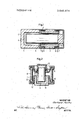
- FIG. 1 is a sectional view of one embodiment of an overvoltage arrester according to the present invention.
- FIG. 2 is a sectional view of another embodiment of an overvoltage arrester according to the present invention.
- electrodes have been enumerated with l and 2, which simultaneously serve as gastight housing for the overvoltage arrester, to a large degree.
- the electrode 1 has the shape of a hollow cylinder with an end wall 1, and its inner diameter is enlarged stagelike at the other, open end 1''.
- a ceramic-glass-metal sealing 6 is arranged at the bottom of the annular tee-slot 13 between the insulating member 2 and the adjacent electrode parts, and it connects the electrode 1 with the insulating member 3 in a gastight manner and mechanically rigid.
- An electrode 2 which is designed as massive, longitudinal cylinder with an end cap, is fixed with the end cap on the other side of the insulating member 3 at its longitudinal member in the same manner as the electrode 1, and it extends freely through the insulating member 3 within the longitudinal cylinder, and centrically into the hollow-cylinder-shaped electrode 1.
- An auxiliary ignition electrode 5 may be fixed at the frontal side of the insulating member 3.
- the electrodes 1 and 2 form a discharge chamber 4 between themselves, opposite which the two annular tee-slots 13 are disposed shaded off by the member 3. Electrode material, which evaporates during the operation of the overvoltage arrester from the discharge chamber 4, cannot reach any of the two annular tee-slots from their partially hidden positions. A galvanic connection between the insulating member 3, on one hand, and the electrodes 1 and 2, on the other hand, is thus practically impossible, since the surfaces 7 in the annual teeslots 13, which extend around in a circle, are safely free of conductive islands and paths.
- an electrode which has been enumerated with 9 has the shape of a metal rod mounted in an end cap 10.
- the end cap 10 which forms a bulge extending in the shape of a V around the metal rod 9 into the gastight housing, is inserted in a gastight manner into one end of a ring-shaped ceramic insulating member 8 with the help of a ceramic-glass-metal sealing 6.
- a second electrode 11 which lies opposite to the rodshaped electrode 9 extends into a pot-shaped electrode 11.
- the part 12 forms an annular slot 13 with the surface 7 of the insulating member 8 which is opposite to it and which extends all around.
- the frontal surface of the electrode 9 and the bottom of the electrode 11 are activated with a matter which lowers the work function.
- the discharge chamber 4 lies between these surfaces, and opposite to the discharge chamber is the annular slot 13, shaded-off by the member 12.
- Electrode material which evaporates during the operation of the overvoltage arrester from the discharge chamber 4 cannot reach the slot 13 from there nor the surface 7 of the insulating member 8 which surface extends around in a circle and lies directly opposite to the V-shaped bulge of the end cap 10.
- a galvanic connection between the insulating member 8 on one hand and the electrodes 9 and 11 on the other hand is thus also practically impossible with the arrester of FIG. 2.
- the ceramic-glass-metal sealing 6 between the insulating members 3 or 8 and the electrodes 1 and 2 or and 11, 12, can be produced in such a way that the open end 1" of the electrode 1 or the end cap of the electrode 2, 10, or 1 l, 12, is glazed according to the prior-known methods of glass-metal connections.
- the electrodes or the electrode caps are heated according to the high-frequency method, and the glazing is melted.
- the glazed electrode parts then connect themselves gastightly with the ceramic of the insulating member and the porous ceramic surface is then sealed by means of the glass.
- Overvoltage arresters with a ceramic-glass-metal sealing also have the advantage that with their preferably suction rod free production, only the electrodes themselves have to be guided exactly, and the exact position of the insulating member is not of such great importance. Tolerances, which agpear between the electrodes and the insulating body during t e production, are namely evened out by means of the ceramic-glass-metal sealing which becomes firm.
- the invention is of particular importance for overvoltage arresters of small dimension.
- the embodiment which is shown in FIG. 1, for instance, has been constructed with a diameter of 8 mm. and a length of 20 mm.
- the invention is not limited to overvoltage arresters with only two electrodes. It may also be applied, with particular advantage, for overvoltage arresters with more than two electrodes, whereby, of course, two electrodes respectively are separated electrically by an insulating member with features according to this invention.
- H" g An overvoltage arrester in a gastight housing including a first electrode and a second electrode arranged opposite one another and a ring-shaped ceramic insulating member which together with said electrodes fonns said housing and means providing a vacuumtight ceramic to metal connection, the improvement therein wherein said means providing said vacuumtight ceramic to metal connection includes portions of said electrodes which surround and embrace said insulating member and including glass at the transitions between said electrodes and said insulating member forming a pressure connection.
- said ceramic ring member has a T-shaped cross section with the horizontal member of the T directed vertically parallel to said axis
- said second electrode includes a longitudinal cylinder and an end cap, said end cap sealed to said ceramic ring member by means of a respective glass portion, said cylinder extending through said ring member, said first electrode shaped as a cup sealed to said ring member by means of a respective glass portion and receiving therein said cylinder.
- said first electrode includes a metal rod and an end cap mounting said rod and having a V-shaped bulge directed generally along the direction of said rod
- said second electrode is cap shaped and receives said rod therein and spaced therefrom, a symmetrical annular member mounting said second electrode, a first of said glass portions sealing said end cap to said ceramic ring member and a second of said electrodes sealing said ceramic ring member to said symmetrical mounting member.
Landscapes
- Chemical & Material Sciences (AREA)
- Engineering & Computer Science (AREA)
- Combustion & Propulsion (AREA)
- Thermistors And Varistors (AREA)
Abstract
Electrode material which is evaporated during overvoltage arresting is prevented from forming in an area between electrodes, the area being shaded by overlapping parts of the overvoltage arrester. In one embodiment the shaded area is formed between an electrode and a ceramic ring having a T-shaped cross section, and in another embodiment between an electrode support member and a ceramic ring. In each embodiment the ceramic ring and the electrodes form a casing for the arrester.
Description
United States Patent Peche Mar. 14, 1972 [54] OVERVOLTAGE ARRESTER [56] References Cited [72] Inventor: Gerhard Peche, Berlin, Germany UNITED STATES PATENTS [73] Assignee: Siemens Aktiengesellschaft, Berlin and 3,454,811 7/1969 Scudner Munich, Germany 3,538,382 11/1970 Smith ..3-17/62 X [22] Filed: 1970 Primary Examiner-James D. Trammell [21] APP] 66,916 Attorney-Hill, Sherman, Meroni, Gross & Simpson [57] ABSTRACT [30] Foreign Apphcauon Pmnty Data Electrode material which is evaporated dun'ng overvoltage ar- Sept. 2, 1969 Germany ..P 19 44 564.8 resting is Prevented from forming in an area between 91% trodes, the area being shaded by overlapping parts of the overvoltage arrester. In one embodiment the shaded area is formed [52] U.S.Cl. ..317/62, 313/DlG. 5 between an electrode and a ceramic ring having a T shaped 1].". Cl. ..H02h cross Section, and in another embodiment between an elec [58] Field of Search ..317/62; SIB/DIG. 5 node support member and a ceramic ring In each embodi,
ment the ceramic ring and the electrodes form a casing for the arrester.
4Claims,2Drawingfigures OVERVOLTAGE ARRESTER BACKGROUND OF THE INVENTION 1. Field of the Invention This invention relates to an overvoltage arrester with a gastight housing, in which electrodes are arranged opposite each other, which electrodes form simultaneously the housing of the overvoltage arrester, with at least one ceramic insulating member, which housing incorporates vacuumtight ceramic-glass-metal sealing.
2. Description of the Prior Art A gas discharge container of the kind to which the present invention is generally concerned and serves as overvoltage arrester is make known in theGerman Letters Patent 930,400. According to an embodiment which is disclosed in that patent, two caplike designed electrodes are respectively slid from one side onto tube-shaped projections of a ring-shaped ceramic insulating member which lies between the tube-shaped projections has a larger outer diameter than the projections and serves as a separation ring for the electrodes, which separation determines the exact electrode distance. A ring-shaped glassmetal sealing, which extends all around the housing, extends over the outer circumference side of the insulating members center part and connects the two electrodes with each other in a vacuumtight manner. After its housing is finished, the overvoltage arrester is pumped empty with a suction rod, filled with inert gas, and connected in a vacuumtight manner by means of a soldering process.
The mechanical strength of the vacuumtight connection represents an essential problem with a prior art overvoltage arrester, since the ring-shaped glass sealing, which runs around the outside of the housing, lies on the outside of the ceramic insulating body with the major portion of its inner surface, and forms a glass-metal sealing which respectively seals the housing only at its two edges in the small width of the electrode-material thickness. The glass-metal scaling is too narrow, compared with the entire width of the glass sealing, to be able to take mechanic stresses to a sufficiently large extent.
Mechanic stresses, however, appear often in the form of impacts, bending or pressure during the transport of overvoltage arresters, during their storage, while handling or operating them. A light impact or a light bending stress, while the overvoltage arrester is inserted into its mounting can, for instance, damage the glass-metal sealing which runs around the outside of the housing, and can destroy the vacuumtight sealing of the housing. Furthermore, a glass sealing which runs around the outside of a connection point of a ceramic insulating member and metallic electrodes is always endangered during operation due to thermic stresses of the differently expanding materials, since glass practically does not bear any tension stress.
Another overvoltage arrester with a cerarnic-glass-metal sealing is made known in the Swiss Letters Patent 341,889. The electrodes of this prior-known overvoltage arrester are designed as area plates which cover the upper and lower surfaces of a ceramic box and which are connected in a vacuumtight manner with the latter withthe help of glazing. Since glass solder can only bear low shearing stresses, the ceramicglass-metal sealing with an overvoltage arrester, according to the above mentioned Swiss patent, is only then stable when the thermic expansion coefficients of ceramic and metal are tuned with regard to each other. A higher as well as a lower expansion coefiicient of the metal, compared with the ceramic, are not applicable, and thus the prior arrangement was never able to gain any practical importance.
A vacuumtight and mechanically stable firm connection among the electrodes and the insulating member, without concern about thermic expansion coefficients might be possible in the form of a hard-solder connection. However, there is an essential problem, namely that insulating between the electrodes is endangered since a part of the hard-soldering material evaporates due to the working processes, during the soldering process. The hard-solder material then can settle on the insulating member, in part, or run along on the latter in liquid form, and cause there conductive islands or paths. If such an island or path is connected galvanically with an electrode, a cathode point can come about on the insulator during a discharge of the overvoltage arrester. At the place of the cathode point, a concentrated heating will appear for a short period of time, which causes strong heat tensions and a cracking of the insulator. The life of such an overvoltage arrester, due to these processes, is very limited, even if no overload occurs which leads to its destruction.
SUMMARY OF THE INVENTION It is thus the primary object of this invention to provide a gastight overvoltage arrester of long lifetime, which safely ensures a sufficient electric insulation between its electrodes during this long lifetime. To realize this primary objective it is proposed that in an over-voltage arrester of the above-men tioned kind, the electrodes at the transition to the ceramic insulating member, which is round according to prior art, embrace the insulating member, also in a ring-shaped manner shrink onto the insulating body after production, and thus mechanically strengthen the ceramic-glass-metal scaling in the manner of a pressure-glass connection. Opposed to the prior overvoltage arresters with a ceramic-glass sealing, there therefore results an arrester having essentially improved mechanical strength.
In a preferred embodiment of the invention, the ceramic insulating member, within the gastight housing, has at least one surface which remains free, which surface extends all around on a side facing away from the longitudinal axis of the overvoltage arrester, and which forms-together with the electrode parts which adjoin the insulating memberan annular tee-slot. On the basis of this annular tee-slot the glass is arranged which forrns the ceramic-glass-metal sealing between the ceramic insulating member and the adjacent electrode portions. This arrangement has the advantage that the surface, which extends around in a circle and which remains free in the annular tee-slots, lies protected against the distribution range of the metal vapors which are produced by are discharges. Thus, the electrode material which is evaporated during operation cannot reach this surface. In this manner, the insulation of the electrodes, which also guarantees the ceramicglass-metal scaling, is also preserved during the operation of the overvoltage arrester. With particular advantage, a disconnected annular tee-slot with a ceramic-glass-metal sealing is provided at each transition from the insulating member to an electrode.
BRIEF DESCRIPTION THE DRAWINGS Other objects, features and advantages of the invention, its organization, construction and operation will be best understood from the following detailed description taken in conjunction with the accompanying drawings, in which:
FIG. 1 is a sectional view of one embodiment of an overvoltage arrester according to the present invention; and
FIG. 2 is a sectional view of another embodiment of an overvoltage arrester according to the present invention.
DESCRIPTION OF THE PREFERRED EMBODIMENTS In FIG. 1, electrodes have been enumerated with l and 2, which simultaneously serve as gastight housing for the overvoltage arrester, to a large degree. A ring-shaped insulating member 3 of ceramic material, which member 3 is T-shaped in cross section, whereby the longitudinal member of the T is directed vertically to the axis and separates the electrodes 1 and 2 from each other electrically. The electrode 1 has the shape of a hollow cylinder with an end wall 1, and its inner diameter is enlarged stagelike at the other, open end 1''. With its open end 1" it is set onto the longitudinal member of the T and it forms an annular tee-slot 13 with its inner surface and a surface 7 of the insulating member 3, which lies opposite to it and which extends all around. A ceramic-glass-metal sealing 6 is arranged at the bottom of the annular tee-slot 13 between the insulating member 2 and the adjacent electrode parts, and it connects the electrode 1 with the insulating member 3 in a gastight manner and mechanically rigid. An electrode 2, which is designed as massive, longitudinal cylinder with an end cap, is fixed with the end cap on the other side of the insulating member 3 at its longitudinal member in the same manner as the electrode 1, and it extends freely through the insulating member 3 within the longitudinal cylinder, and centrically into the hollow-cylinder-shaped electrode 1. An auxiliary ignition electrode 5 may be fixed at the frontal side of the insulating member 3.
The electrodes 1 and 2 form a discharge chamber 4 between themselves, opposite which the two annular tee-slots 13 are disposed shaded off by the member 3. Electrode material, which evaporates during the operation of the overvoltage arrester from the discharge chamber 4, cannot reach any of the two annular tee-slots from their partially hidden positions. A galvanic connection between the insulating member 3, on one hand, and the electrodes 1 and 2, on the other hand, is thus practically impossible, since the surfaces 7 in the annual teeslots 13, which extend around in a circle, are safely free of conductive islands and paths.
In FIG. 2, an electrode which has been enumerated with 9, has the shape of a metal rod mounted in an end cap 10. The end cap 10, which forms a bulge extending in the shape of a V around the metal rod 9 into the gastight housing, is inserted in a gastight manner into one end of a ring-shaped ceramic insulating member 8 with the help of a ceramic-glass-metal sealing 6. A second electrode 11 which lies opposite to the rodshaped electrode 9 extends into a pot-shaped electrode 11. A metal part 12 extending symmetrically around the outer edge of the pot-shaped electrode 11, which is inserted in the same manner gas-tightly into the other end of the ring-shaped insulating member 8, extends into the gastight housing and mounts the pot-shaped electrode 1 l. The part 12 forms an annular slot 13 with the surface 7 of the insulating member 8 which is opposite to it and which extends all around. The frontal surface of the electrode 9 and the bottom of the electrode 11 are activated with a matter which lowers the work function. The discharge chamber 4 lies between these surfaces, and opposite to the discharge chamber is the annular slot 13, shaded-off by the member 12. Electrode material which evaporates during the operation of the overvoltage arrester from the discharge chamber 4, cannot reach the slot 13 from there nor the surface 7 of the insulating member 8 which surface extends around in a circle and lies directly opposite to the V-shaped bulge of the end cap 10. A galvanic connection between the insulating member 8 on one hand and the electrodes 9 and 11 on the other hand is thus also practically impossible with the arrester of FIG. 2.
The ceramic-glass-metal sealing 6 between the insulating members 3 or 8 and the electrodes 1 and 2 or and 11, 12, can be produced in such a way that the open end 1" of the electrode 1 or the end cap of the electrode 2, 10, or 1 l, 12, is glazed according to the prior-known methods of glass-metal connections. During the sealing process, the electrodes or the electrode caps are heated according to the high-frequency method, and the glazing is melted. The glazed electrode parts then connect themselves gastightly with the ceramic of the insulating member and the porous ceramic surface is then sealed by means of the glass. However, it is also possible to first melt the glass onto the ceramic. By means of the radiation heat of the heated electrode parts, the glass melts and connects the insulating member gastightly with the electrodes. Mechanical strength and temperature resistance of such a ceramic-glassmetal connection and a hard-solder connection are comparatively equally good.
Overvoltage arresters with a ceramic-glass-metal sealing also have the advantage that with their preferably suction rod free production, only the electrodes themselves have to be guided exactly, and the exact position of the insulating member is not of such great importance. Tolerances, which agpear between the electrodes and the insulating body during t e production, are namely evened out by means of the ceramic-glass-metal sealing which becomes firm.
The invention is of particular importance for overvoltage arresters of small dimension. The embodiment which is shown in FIG. 1, for instance, has been constructed with a diameter of 8 mm. and a length of 20 mm.
The invention is not limited to overvoltage arresters with only two electrodes. It may also be applied, with particular advantage, for overvoltage arresters with more than two electrodes, whereby, of course, two electrodes respectively are separated electrically by an insulating member with features according to this invention.
Many changes and modifications may be made in the invention by one skilled in the art without departing from the spirit and scope thereof, and it is to be understood that I intend to include within the patent warranted hereon all such changes and modifications as may reasonably and properly be included within the scope of my contribution to the art.
I claim as my invention: H" g 1. An overvoltage arrester in a gastight housing including a first electrode and a second electrode arranged opposite one another and a ring-shaped ceramic insulating member which together with said electrodes fonns said housing and means providing a vacuumtight ceramic to metal connection, the improvement therein wherein said means providing said vacuumtight ceramic to metal connection includes portions of said electrodes which surround and embrace said insulating member and including glass at the transitions between said electrodes and said insulating member forming a pressure connection.
2. An overvoltage arrester as set forth in claim 1, wherein said arrester has a longitudinal axis, said ceramic ring member includes a pair of first annular surface facing away from said axis and said first and second electrodes includes a pair of second annular surfaces respectively spaced from said first annular surfaces to form a pair of annular slots, said glass portions disposed in said slots.
3. An overvoltage arrester according to claim 2, wherein said ceramic ring member has a T-shaped cross section with the horizontal member of the T directed vertically parallel to said axis, said second electrode includes a longitudinal cylinder and an end cap, said end cap sealed to said ceramic ring member by means of a respective glass portion, said cylinder extending through said ring member, said first electrode shaped as a cup sealed to said ring member by means of a respective glass portion and receiving therein said cylinder.
4. An overvoltage arrester according to claim I, wherein said first electrode includes a metal rod and an end cap mounting said rod and having a V-shaped bulge directed generally along the direction of said rod, said second electrode is cap shaped and receives said rod therein and spaced therefrom, a symmetrical annular member mounting said second electrode, a first of said glass portions sealing said end cap to said ceramic ring member and a second of said electrodes sealing said ceramic ring member to said symmetrical mounting member.
Claims (4)
1. An overvoltage arrester in a gastight housing including a first electrode and a second electrode arranged opposite one another and a ring-shaped ceramic insulating member which together with said electrodes forms said housing and means providing a vacuumtight ceramic to metal connection, the improvement therein wherein said means providing said vacuumtight ceramic to metal connection includes portions of said electrodes which surround and embrace said insulating member and including glass at the transitions between said electrodes and said insulating member forming a pressure connection.
2. An overvoltage arrester as set forth in claim 1, wherein said arrester has a longitudinal axis, said ceramic ring member includes a pair of first annular surface facing away from said axis and said first and second electrodes includes a pair of second annular surfaces respectively spaced from said first annular surfaces to form a pair of annular slots, said glass portions disposed in said slots.
3. An overvoltage arrester according to claim 2, wherein said ceramic ring member has a T-shaped cross section with the horizontal member of the T directed vertically parallel to said axis, said second electrode includes a longitudinal cylinder and an end cap, said end cap sealed to said ceramic ring member by means of a respective glass portion, said cylinder extending through said ring member, said first electrode shaped as a cup sealed to said ring member by means of a respective glass portion and receiving therein sAid cylinder.
4. An overvoltage arrester according to claim 1, wherein said first electrode includes a metal rod and an end cap mounting said rod and having a V-shaped bulge directed generally along the direction of said rod, said second electrode is cap shaped and receives said rod therein and spaced therefrom, a symmetrical annular member mounting said second electrode, a first of said glass portions sealing said end cap to said ceramic ring member and a second of said electrodes sealing said ceramic ring member to said symmetrical mounting member.
Applications Claiming Priority (1)
| Application Number | Priority Date | Filing Date | Title |
|---|---|---|---|
| DE19691944564 DE1944564C3 (en) | 1969-09-02 | Surge arresters |
Publications (1)
| Publication Number | Publication Date |
|---|---|
| US3649874A true US3649874A (en) | 1972-03-14 |
Family
ID=5744430
Family Applications (1)
| Application Number | Title | Priority Date | Filing Date |
|---|---|---|---|
| US66916A Expired - Lifetime US3649874A (en) | 1969-09-02 | 1970-08-26 | Overvoltage arrester |
Country Status (8)
| Country | Link |
|---|---|
| US (1) | US3649874A (en) |
| JP (1) | JPS516856B1 (en) |
| AT (1) | AT303873B (en) |
| CH (1) | CH517391A (en) |
| FR (1) | FR2060351B1 (en) |
| GB (1) | GB1274393A (en) |
| SE (1) | SE358995B (en) |
| ZA (1) | ZA706001B (en) |
Cited By (12)
| Publication number | Priority date | Publication date | Assignee | Title |
|---|---|---|---|---|
| US3772570A (en) * | 1971-02-11 | 1973-11-13 | Siemens Ag | Gas-discharge overvoltage arrester |
| US3775642A (en) * | 1971-01-25 | 1973-11-27 | Siemens Ag | Gas discharge excess voltage arrester |
| US3849704A (en) * | 1972-10-27 | 1974-11-19 | Franklin Electric Co Inc | Lightning arrestor |
| US3878423A (en) * | 1973-05-31 | 1975-04-15 | Comtelco Uk Ltd | Electrical surge arrestor having fail-safe properties |
| US4142220A (en) * | 1977-09-26 | 1979-02-27 | Reliable Electric Company | Multi arc gap surge arrester |
| US4175277A (en) * | 1976-11-08 | 1979-11-20 | Bell Telephone Laboratories, Incorporated | Voltage surge protector |
| FR2459547A1 (en) * | 1979-06-21 | 1981-01-09 | Materiel Telephonique | Lightning discharge protector for telephone exchange circuits - has two terminals sealed in cylindrical metal tube, one comprising cylindrical base contg. discharge assisting material pellet |
| US4320435A (en) * | 1979-03-06 | 1982-03-16 | Tii Industries, Inc. | Surge arrester assembly |
| US4394704A (en) * | 1979-03-06 | 1983-07-19 | Tii Corporation | Surge arrester assembly |
| US4769736A (en) * | 1986-06-25 | 1988-09-06 | Siemens Aktiengesellschaft | Gas discharge surge arrester |
| US20080218082A1 (en) * | 2005-08-02 | 2008-09-11 | Epcos Ag | Spark-Discharge Gap |
| US11025037B2 (en) * | 2017-07-05 | 2021-06-01 | Tdk Electronics Ag | Arrester for protection against overvoltages |
Families Citing this family (3)
| Publication number | Priority date | Publication date | Assignee | Title |
|---|---|---|---|---|
| JP4687503B2 (en) * | 2006-02-28 | 2011-05-25 | 三菱マテリアル株式会社 | surge absorber |
| JP4770550B2 (en) * | 2006-03-29 | 2011-09-14 | 三菱マテリアル株式会社 | surge absorber |
| EP3330892A1 (en) | 2016-11-30 | 2018-06-06 | Ricoh Company Ltd. | Information processing apparatus, imaging device, device control system, mobile object, information processing method, and carrier means |
Citations (2)
| Publication number | Priority date | Publication date | Assignee | Title |
|---|---|---|---|---|
| US3454811A (en) * | 1967-04-18 | 1969-07-08 | Bell Telephone Labor Inc | Gas tube surge (overload) protection device |
| US3538382A (en) * | 1968-01-19 | 1970-11-03 | Gen Electric | Triggered vacuum gap overvoltage protective device |
Family Cites Families (5)
| Publication number | Priority date | Publication date | Assignee | Title |
|---|---|---|---|---|
| DE714139C (en) * | 1938-04-26 | 1941-11-21 | Siemens & Halske Akt Ges | Surge arresters |
| GB622645A (en) * | 1945-03-10 | 1949-05-05 | Mallory & Co Inc P R | Improvements in methods of making spark gaps, apparatus therefor, and product thereof |
| GB648997A (en) * | 1948-04-06 | 1951-01-17 | Siemens Electric Lamps & Suppl | Improvements relating to electrical excess voltage protective devices |
| GB839083A (en) * | 1957-03-15 | 1960-06-29 | British Thomson Houston Co Ltd | Improvements in vacuum type electric switches |
| GB874215A (en) * | 1958-10-24 | 1961-08-02 | Gen Electric | Improvements in electric overvoltage discharge device |
-
1970
- 1970-08-26 US US66916A patent/US3649874A/en not_active Expired - Lifetime
- 1970-08-31 CH CH1298670A patent/CH517391A/en not_active IP Right Cessation
- 1970-08-31 FR FR7031639A patent/FR2060351B1/fr not_active Expired
- 1970-08-31 AT AT789470A patent/AT303873B/en not_active IP Right Cessation
- 1970-09-01 ZA ZA706001A patent/ZA706001B/en unknown
- 1970-09-01 GB GB41751/70A patent/GB1274393A/en not_active Expired
- 1970-09-02 SE SE11962/70A patent/SE358995B/xx unknown
- 1970-09-02 JP JP45076424A patent/JPS516856B1/ja active Pending
Patent Citations (2)
| Publication number | Priority date | Publication date | Assignee | Title |
|---|---|---|---|---|
| US3454811A (en) * | 1967-04-18 | 1969-07-08 | Bell Telephone Labor Inc | Gas tube surge (overload) protection device |
| US3538382A (en) * | 1968-01-19 | 1970-11-03 | Gen Electric | Triggered vacuum gap overvoltage protective device |
Cited By (13)
| Publication number | Priority date | Publication date | Assignee | Title |
|---|---|---|---|---|
| US3775642A (en) * | 1971-01-25 | 1973-11-27 | Siemens Ag | Gas discharge excess voltage arrester |
| US3772570A (en) * | 1971-02-11 | 1973-11-13 | Siemens Ag | Gas-discharge overvoltage arrester |
| US3849704A (en) * | 1972-10-27 | 1974-11-19 | Franklin Electric Co Inc | Lightning arrestor |
| US3878423A (en) * | 1973-05-31 | 1975-04-15 | Comtelco Uk Ltd | Electrical surge arrestor having fail-safe properties |
| US4175277A (en) * | 1976-11-08 | 1979-11-20 | Bell Telephone Laboratories, Incorporated | Voltage surge protector |
| US4142220A (en) * | 1977-09-26 | 1979-02-27 | Reliable Electric Company | Multi arc gap surge arrester |
| US4394704A (en) * | 1979-03-06 | 1983-07-19 | Tii Corporation | Surge arrester assembly |
| US4320435A (en) * | 1979-03-06 | 1982-03-16 | Tii Industries, Inc. | Surge arrester assembly |
| FR2459547A1 (en) * | 1979-06-21 | 1981-01-09 | Materiel Telephonique | Lightning discharge protector for telephone exchange circuits - has two terminals sealed in cylindrical metal tube, one comprising cylindrical base contg. discharge assisting material pellet |
| US4769736A (en) * | 1986-06-25 | 1988-09-06 | Siemens Aktiengesellschaft | Gas discharge surge arrester |
| US20080218082A1 (en) * | 2005-08-02 | 2008-09-11 | Epcos Ag | Spark-Discharge Gap |
| US8169145B2 (en) * | 2005-08-02 | 2012-05-01 | Epcos Ag | Spark-discharge gap for power system protection device |
| US11025037B2 (en) * | 2017-07-05 | 2021-06-01 | Tdk Electronics Ag | Arrester for protection against overvoltages |
Also Published As
| Publication number | Publication date |
|---|---|
| DE1944564B2 (en) | 1975-04-30 |
| FR2060351B1 (en) | 1974-03-22 |
| DE1944564A1 (en) | 1971-03-04 |
| CH517391A (en) | 1971-12-31 |
| AT303873B (en) | 1972-12-11 |
| FR2060351A1 (en) | 1971-06-18 |
| SE358995B (en) | 1973-08-13 |
| JPS516856B1 (en) | 1976-03-02 |
| GB1274393A (en) | 1972-05-17 |
| ZA706001B (en) | 1971-04-28 |
Similar Documents
| Publication | Publication Date | Title |
|---|---|---|
| US3649874A (en) | Overvoltage arrester | |
| US3868593A (en) | Hollow-cathode laser tube | |
| US3878423A (en) | Electrical surge arrestor having fail-safe properties | |
| US4749905A (en) | High pressure discharge lamp | |
| US3289027A (en) | Gas filled excess voltage protector having electrodes of non-uniform diameter | |
| USRE38234E1 (en) | Ultraviolet detector | |
| US3936767A (en) | Cold cathode gas lasers | |
| GB1591150A (en) | Gas discharge surge arresters | |
| EP1191572B1 (en) | Short-arc discharge lamp | |
| US2114869A (en) | Quartz-to-metal seal | |
| US7602126B2 (en) | Flash discharge lamp | |
| DE452346C (en) | Electric discharge tube, the outer wall of which is partly made of metal | |
| EP0160316A2 (en) | Single-ended high intensity discharge lamp and manufacture | |
| US2556855A (en) | Gaseous discharge device | |
| US2449961A (en) | Electrical protective device | |
| CA1043850A (en) | Electric lamp with butt welded molybdenum tungsten conductors | |
| US20050082984A1 (en) | Alloy for a lead member of an electric lamp and electrode structure of the electric lamp | |
| US3772570A (en) | Gas-discharge overvoltage arrester | |
| US2056035A (en) | Electrode structure for metal tubes | |
| US3775642A (en) | Gas discharge excess voltage arrester | |
| KR100712745B1 (en) | Electric lamp | |
| US2741680A (en) | Overvoltage arrestor with a discharge in a low temperature atmosphere | |
| US2174381A (en) | Glass-to-metal seal | |
| JPH0453010Y2 (en) | ||
| JPH0219593B2 (en) |