US3604483A - Machine for automatically producing framelike structures - Google Patents
Machine for automatically producing framelike structures Download PDFInfo
- Publication number
- US3604483A US3604483A US821286A US3604483DA US3604483A US 3604483 A US3604483 A US 3604483A US 821286 A US821286 A US 821286A US 3604483D A US3604483D A US 3604483DA US 3604483 A US3604483 A US 3604483A
- Authority
- US
- United States
- Prior art keywords
- machine
- displacement
- clamping means
- units
- finger
- Prior art date
- Legal status (The legal status is an assumption and is not a legal conclusion. Google has not performed a legal analysis and makes no representation as to the accuracy of the status listed.)
- Expired - Lifetime
Links
- 239000011521 glass Substances 0.000 claims abstract description 16
- 238000006073 displacement reaction Methods 0.000 claims description 43
- 210000000078 claw Anatomy 0.000 claims description 19
- 238000007789 sealing Methods 0.000 claims description 18
- 210000001145 finger joint Anatomy 0.000 claims description 12
- 230000008707 rearrangement Effects 0.000 claims description 11
- 230000001681 protective effect Effects 0.000 claims description 5
- 241001074085 Scophthalmus aquosus Species 0.000 abstract description 8
- 238000004519 manufacturing process Methods 0.000 description 12
- 239000003292 glue Substances 0.000 description 9
- 239000012530 fluid Substances 0.000 description 5
- 238000005304 joining Methods 0.000 description 5
- 238000005520 cutting process Methods 0.000 description 3
- 230000004048 modification Effects 0.000 description 3
- 238000012986 modification Methods 0.000 description 3
- 238000003780 insertion Methods 0.000 description 2
- 230000037431 insertion Effects 0.000 description 2
- 239000000463 material Substances 0.000 description 2
- 230000000284 resting effect Effects 0.000 description 2
- 101100421200 Caenorhabditis elegans sep-1 gene Proteins 0.000 description 1
- 229920001875 Ebonite Polymers 0.000 description 1
- 235000012571 Ficus glomerata Nutrition 0.000 description 1
- 240000000365 Ficus racemosa Species 0.000 description 1
- 241001591024 Samea Species 0.000 description 1
- 235000015125 Sterculia urens Nutrition 0.000 description 1
- 230000009471 action Effects 0.000 description 1
- 230000003213 activating effect Effects 0.000 description 1
- 238000004026 adhesive bonding Methods 0.000 description 1
- 238000010276 construction Methods 0.000 description 1
- 238000009826 distribution Methods 0.000 description 1
- 230000000694 effects Effects 0.000 description 1
- 230000005489 elastic deformation Effects 0.000 description 1
- 230000007246 mechanism Effects 0.000 description 1
- 238000000465 moulding Methods 0.000 description 1
- 238000010422 painting Methods 0.000 description 1
- 238000003825 pressing Methods 0.000 description 1
- 239000012858 resilient material Substances 0.000 description 1
- 238000010186 staining Methods 0.000 description 1
- 230000001360 synchronised effect Effects 0.000 description 1
- 238000009966 trimming Methods 0.000 description 1
- 239000002023 wood Substances 0.000 description 1
Images


Classifications
-
- B—PERFORMING OPERATIONS; TRANSPORTING
- B27—WORKING OR PRESERVING WOOD OR SIMILAR MATERIAL; NAILING OR STAPLING MACHINES IN GENERAL
- B27M—WORKING OF WOOD NOT PROVIDED FOR IN SUBCLASSES B27B - B27L; MANUFACTURE OF SPECIFIC WOODEN ARTICLES
- B27M3/00—Manufacture or reconditioning of specific semi-finished or finished articles
- B27M3/0013—Manufacture or reconditioning of specific semi-finished or finished articles of composite or compound articles
- B27M3/0066—Manufacture or reconditioning of specific semi-finished or finished articles of composite or compound articles characterised by tongue and groove or tap hole connections
-
- E—FIXED CONSTRUCTIONS
- E04—BUILDING
- E04G—SCAFFOLDING; FORMS; SHUTTERING; BUILDING IMPLEMENTS OR AIDS, OR THEIR USE; HANDLING BUILDING MATERIALS ON THE SITE; REPAIRING, BREAKING-UP OR OTHER WORK ON EXISTING BUILDINGS
- E04G21/00—Preparing, conveying, or working-up building materials or building elements in situ; Other devices or measures for constructional work
- E04G21/24—Safety or protective measures preventing damage to building parts or finishing work during construction
- E04G21/30—Safety or protective measures preventing damage to building parts or finishing work during construction against mechanical damage or dirt, e.g. guard covers of stairs
-
- E—FIXED CONSTRUCTIONS
- E06—DOORS, WINDOWS, SHUTTERS, OR ROLLER BLINDS IN GENERAL; LADDERS
- E06B—FIXED OR MOVABLE CLOSURES FOR OPENINGS IN BUILDINGS, VEHICLES, FENCES OR LIKE ENCLOSURES IN GENERAL, e.g. DOORS, WINDOWS, BLINDS, GATES
- E06B3/00—Window sashes, door leaves, or like elements for closing wall or like openings; Layout of fixed or moving closures, e.g. windows in wall or like openings; Features of rigidly-mounted outer frames relating to the mounting of wing frames
- E06B3/54—Fixing of glass panes or like plates
- E06B3/5454—Fixing of glass panes or like plates inside U-shaped section members
-
- E—FIXED CONSTRUCTIONS
- E06—DOORS, WINDOWS, SHUTTERS, OR ROLLER BLINDS IN GENERAL; LADDERS
- E06B—FIXED OR MOVABLE CLOSURES FOR OPENINGS IN BUILDINGS, VEHICLES, FENCES OR LIKE ENCLOSURES IN GENERAL, e.g. DOORS, WINDOWS, BLINDS, GATES
- E06B3/00—Window sashes, door leaves, or like elements for closing wall or like openings; Layout of fixed or moving closures, e.g. windows in wall or like openings; Features of rigidly-mounted outer frames relating to the mounting of wing frames
- E06B3/66—Units comprising two or more parallel glass or like panes permanently secured together
Definitions
- the machine includes a number of adjustably posi- [54] MACHINE FOR AUTOMATICALLY PRODUCING tioned units corresponding in number to the number of frame FRAMEUKE STRUCTURES components, and each unit carries a pair of slrdeably mounted 9 Claims, 16 Drawing Figs. clamping members disposed at an angle with each other and adapted to engage the ends of ad acent frame components.
- a U.S. finger cutter is also carried on each unit and is 144/134 mounted to move in a path which bisects the paths of the two 327m clamping members.
- a hydraulic system is provided for selec- 3, tively displacing the clamping members and finger cutter uch l 7 that interengaging fingers are cut in the adjacent component 535 ends as the components are displaced toward each other to form the completed frame.
- Means may also be provided for [56] References Clted positioning a panel such as a glass windowpane intermediate UNITED STATES PATENTS the components such that the panel may be mounted in precut 1,151,892 8/1915 Madsen 144/3 X grooves in the components during the assembly operation.
- FIG. 16 is an end view taken from the plane XVI-XVI in FIG. 14.
- a preferred embodiment of the machine of the invention relates to a ma hin fo t tiwhich is shown in FIG. l-3 is adapted for the manufacture of cally producing framelike structures having mitered finger joints and using fingers of very small size, i.e., with a finger height of less than is inch and preferably between l/l6 inch and A inch.
- window frames which are permanently joined along the windowpane.
- a further object of the invention is to provide for sealing strips to be placed on the edges of a windowpane before its introduction in the machine of the kind referred to and which are formed so as to ensure a proper introduction of the said pane in grooves or notches in the frame components during assembly of the same in the machine.
- Still another object of the invention is to provide for a protective covering to be placed at least on one side of the glass pane to protect the same during its handling in the machine.
- the machine according to the invention may be applicable for handling of any other materials which may be joined by glueing and which are suitable for cutting out fingers.
- FIG. 1 is a plan view diagrammatically showing a preferred embodiment of a machine according to the invention provided for the manufacturing of rectangular frames and with its moving parts in a first position,
- FIGS. 2 and 3 are plan views of the same in a second and third position
- FIG. 4 is a vertical section through a part of the machine taken substantially along the line IV-IV of FIG. 1,
- FIG. 5 shows schematically a part of the hydraulic system of the machine connected with one of the machine clamping devices shown in the first position
- FIGS. 6 and 7 show the same clamping devices shown in the second and third position
- FIG. 8 is an elevation schematically showing a part of the machine conveyor means
- FIG. 9 is a part of a panel or windowpane with sealing strips for introducing into the machine
- FIG. 10 is a section through a part of a spaced double panes of glass provided with sealing strip and protective covering in section,
- FIG. 11 shows in section the same inserted in the window frame
- FIG. 12 shows a part of a single glass pane with another embodiment of the sealing strip and protective cover in section
- FIG. 13 shows a section of the same inserted in the window frame
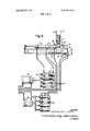
- FIG. 14 is an elevation partly in section of another embodiment of the clamping device taken along the line XIV-XIV of FIG. 15,
- FIG. 15 is a plan view of the same.
- each of the units 1, 2, 3 and 4 is placed on a plain table resp. 5, 6, 7 and 8 which may be built into the floor and provided with a grinded upper surface so as to ensure exact position of the four units.
- the well-known air cushion effect may be used in the units having provisions for supply of pressure air to beneath their undersurface which is surrounded by appropriate sealing means.
- Each unit comprises a frame preferably made as a casing with a nearby quadratic horizontal cross section and which on two adjacent sides is provided with guides for slides carrying clamping means indicated generally by the numeral 16 and which are going to be more fully described below.
- the guides are so arranged that the two slides of a unit can be moved horizontally in rectilinear paths which are perpendicular to each other.
- Each unit has at its top a guide 9 for a slide 10 carrying a cutter assembly, the guide 9 being so arranged that the slide 10 can perform a rectilinear movement in a direction which intersects the angle between the direction of movement of the two clamping means 16.
- the movement of the slide 10 in the guide 9 is accomplished by a double-acting hydraulic cylinder 14 placed inside the guide 9 and having the end of its piston rod secured to the slide 10.
- the cutter assembly comprising a motor 11 with a vertical shaft carrying on its lower end a cutter 12 provided with blades for cutting, tapering fingers and preferably also blades for trimming the tips of the fingers.
- the cutter assembly is mounted on a cylindrical support the axis of which is parallel with but slightly eccentric with the axis of rotation of the cutter and the motor.
- This support is mounted rotatably and axially displaceable in a bearing I3 secured to the one end of the slide 10.
- This turning of the cutter assembly is accomplished by a double-acting hydraulic cylinder 19 the piston rod of which is acting on a gear sector, meshing with a gear provided on the cutter assembly cylindrical support which is further provided with a short thread or helical groove cooperating with a thread or pin in the bearing 13 in such a way that the cutter assembly concurrently with the said turning over about will be displaced in axial direction a short distance which corresponds to half the width of the fingers to be cut in the frame elements, for a purpose which will be explained below.
- Each of the clamping means 16 comprises a slide 22 movable in a guide 23 fixed to the sidewall of the casing of the unit.
- This slide is provided with a horizontal supporting surface 24 and an adjacent vertical abutment surface 25 to ensure an exact positioning of the components which in general are indicated by the numeral 15. It will be understood that these surfaces may be'formed in another way to accommodate special profiles of the frame components or mouldings.
- the slide 22 carries at its upper part a claw which in general is indicated by 26 and which by means of a hydraulic cylinder 26' is moved in a vertical direction so as to clamp with its under surface a frame component which is placed on the slide in abutment with the surfaces 24 and 25.
- This hydraulic system comprises a double-acting hydraulic cylinder 27 with a piston and a piston rod the end of which is secured to a protruding part of the casing of the unit.
- a further doubleacting hydraulic cylinder 28 is placed in continuation of the cylinder 27 and is provided with a piston and a piston rod the end of which is secured to the slide 22.
- Each end of the cylinder 27 communicates through a flexible tube with corresponding ends of a control cylinder 29 and each end of the cylinder 28 communicates over flexible tubes with corresponding ends of a control cylinder 30.
- control cylinders 29 and 30 will each form part of an aggregate consisting of eight control cylinders 29 and 30 respectively.
- the ends of the piston rods of the eight control cylinders 29 are connected to a common yoke 31 which is acted upon by a double-acting hydraulic power cylinder 32.
- the piston rods of the eight control cylinders 30 are connected to a common yoke 33 acted upon by a double-acting hydraulic cylinder 34.
- the hydraulic cylinders 27 and 28 of the machines eight clamping devices are acted upon simultaneously by the said aggregate of control cylinders and power cylinders, which for the sake of cleamess are not shown in FIGS. 1-3 and which are placed on a convenient place so that connecting flexible tubes between all the cylinders will have nearby equal lengths so as to minimize deviations in the movement of the working cylinders owing to elastic deformation of the flexible tubes when subjected to the hydraulic pressure.
- the power cylinders 32 and 34 are connected to a common source of hydraulic pressure fluid which also feeds the other hydraulic cylinders of the machine, and a supply of hydraulic pressure fluid is governed by appropriate hydraulic control means well known in the art.
- the frame components are supplied from four magazines which are placed over the spaces between the units so that they may be continuously filled up from the floor over the machine through apertures in the floor.
- the lower end of one of the magazines is indicated in FIGS. 5-7 by two guiding rails 35 and 36 between which the frame components are moving downward successively and where the lowest component is resting on the upper surface of the claw 26.
- FIG. 5 shows the slide 22 in its most retracted position where a frame component 15' guided by a retractable rail 37 in a way which will be described below has fallen down to the position shown in front of the claw 26.
- pressure fluid is supplied to the power cylinder 32 to move the pistons in the eight control cylinders 29 whereby the piston rod of the hydraulic cylinder 27 will be pressed out to move the slide 22 forward against the position shown in FIG. 6.
- the frame component 15' will under the influence of the rail 36 be brought into abutment with the surfaces 24 and 25 whereafter pressure fluid is supplied to the hydraulic cylinder 26' so as to lower the claw 26 to effectively clamp the frame component 15'.
- the piston in the power cylinder 32 has reached the end of its stroke which may be determined by an adjustable stop, all the slides 22 of the machine will simultaneously have reached a first working position shown in FIG. 6 and 2.
- Each of the units is provided with a glue-applying apparatus shown schematically by 20 and which may be of any suitable construction well known in the art.
- the glue applying apparatuses of the four units are activated for applying glue to the fingers just cut in the ends of the frame components. This is done by activating a hydraulic cylinder to raise glue applying implements which are submerged in glue containers so as to pass the end surfaces of the frame components to which the glue is to be applied.
- the table 46 islowered by releasing of the pressure in the hydraulic cylinder 45 until the frame has come to rest on a conveyor comprising two endless belts 40 and 41 supported by rollers attached to the respective units in such a way as to accommodate mutual displacement of the units by rearranging the machine for production of frames of another dimension.
- a conveyor comprising two endless belts 40 and 41 supported by rollers attached to the respective units in such a way as to accommodate mutual displacement of the units by rearranging the machine for production of frames of another dimension.
- they are driven by the same motor and their respective driving rollers being interconnected by a telescopic shaft 42.
- these strips have the important purpose of eliminating small inaccuracies between the glass panes and the frame components and especially by their tapering profile to ensure a proper insertion in the grooves of the frame components by the automatic joining of the same as otherwise the pane inevitably would be crushed causing wasteful interruptions of the continuous manufacturing process.
- FIG. 9-13 The sealing strips adapted for this purpose are shown in FIG. 9-13.
- FIG. 9 shows a comer of a windowpane 47 on the edges of which are mounted sealing strips 72 of resilient material. The strips are cut to lengths to form a mitre joint at the corners but with a narrow gap 73 between adjacent strips.
- FIGS. 10 and 11 show a double-pane window with two glass panes 47 and 47 which along their periphery are hermetically sealed by 74.
- the sealing strip 72 placed on the edge of the pane has a generally U-shaped cross section with two legs 76 and 77 and a bottom 75.
- the bottom 75 will show a somewhat arcuate profile so that it will bend away from the edge of the pane.
- the legs 76 and 77 have at their free ends inturning lips 78 and 79, resp. which will cause the legs also to diverge from the surface of the pane.
- the legs 76 and 77 further have at their ends joining the bottom 75 extensions which at least with the outer surfaces 80 and 81, resp. are tapering outwards against the median plane of the pane. This will greatly facilitate and ensure proper introduction of the pane in the groove 84 in the frame member 15 by the assembly of the frame in the machine. Further these extensions will in the assembled window by being bent inwardly together with deformation of the bottom 75 which will be straightened out as shown in FIG. 11 ensure that the pane in the assembled window will be elastically clamped to a certain extent and compensate for small'inaccuracies in the dimensions of the pane and the frame members.
- At least one side of the pane and preferably both sides of the pane are covered with a thin sheet or film 82 preferably of plastic.
- This covering which for the sake of clearness in the drawings is shown in some distance from the pane will in practice lie adjacent the surfaces of the pane and may be of a semiadhering type which will facilitate applying of the covering to the pane in a highly mechanized manufacturing process.
- the covering 82 is placed inside the sealing strips 72 but it may also be placed around the sealing strips and thereby assist in keeping the sealing strips on place during the handling of the glass panes in the machine.
- the covering When the windows are going to be taken into use the covering may easily be removed and discarded by cutting it along the edges of the sealing strips or frame members.
- the part of the covering which is hidden inside the grooves84 is harmless and may be left in place.
- the covering 82 also substantially will facilitate subsequent treatment of the windows such as painting or staining as well as protecting the pane during transportation and handling.
- FIGS. 12 and 13 A simplified modification of the sealing strip is shown in FIGS. 12 and 13. By this embodiment only the one. leg 76 of the U-formed strip is extended over the bottom 75 which'only diverges from the pane 47 at its one end. The elastic'deformation of the sealing strip by inserting in the groove of the frame member 15 will appear from FIG. 13.
- FIGS. 14-16 which only show relevant parts of one of the clamping means 16 the claw 26 is provided with a depending bushing 50 guided for vertical movement in a corresponding bore in the slide 22.
- the bushing 50 has an internal thread into which a threaded spindle 51 is screwed.
- the spindle 51 is at its upper end provided with a hexagonal aperture for insertion of a key, whereby the spindle may be turned to adjust the height'of the claw 26 in accordance with the height of the frame component 15 to be handled by the machine.
- the spindle 51 is extended by a threaded bolt 52 screwed into the spindle and the diameter of which is less than the diameter of the spindle 51.
- the bolt 52 is provided with a circumferential groove 52.
- the lower part of the bore in the slide 22 has an internal thread in which a disc 54 is screwed in and locked, the disc serving as abutment for spring means 55, for instance disc springs, which at their other end abut against the spindle 51.
- spring means 55 for instance disc springs, which at their other end abut against the spindle 51.
- Similar spring means 56 are inserted between a collar forming the upper confinement of the peripherical groove 53 and the disc 54.
- a lever 58 is mounted joumaled about a pin 57.
- the one end 59 of the lever 58 is forked so as to be engaged in the circumferential groove 53 and the other end of the lever has a cam follower 60 with a special profile as shown in FIG. 14 and adapted for cooperation with a fixed cam 61 secured to the casing of the unit.
- the spring means 55 are compressed.
- the cam follower 60 will pass over the forward edge of the cam 61 thereby releasing the lever 58 so that the same by the compressed spring 55 will be turned in the direction against the sun, will be raised and release the frame member 15.
- the cam follower 60 having a rounded upper surface will by engaging an inclined forward surface of the cam 61 move under the cam 61 whereby the spring means 56 are compressed against the undersurface of the disc 54.
- a machine for automatically producing frames or framelike structures assembled by glued finger joints comprising a number of substantially identical units corresponding in number to the number of corners in the frame, means for supporting said units for selective displacement in a horizontal plane to permit rearrangement into desired mutual positions, means for locking the units in said desired positions, each unit comprising two slideably mounted clamping means positioned for displacement in a horizontal plane in rectilinear paths forming an angle with each other, a slideably mounted finger cutter positioned for displacement in a horizontal linear path bisecting the angle between the paths for the displacement of the clamping means, a glue-applying apparatus, and hydraulic means for simultaneously displacing the clamping means and finger cutter respectively, means for supplying cut to size frame components to the machine, and means for removing assembled frames from the machine.
- a machine for automatically producing frames or framelike structures assembled by glued finger joints comprising a number of substantially identical units corresponding in number to the number of corners in the frame, means for supporting said units for selective displacement in a horizontal plane to permit rearrangement into desired mutual positions, means for locking the units in said desired positions, each unit comprising two slideably mounted clamping means positioned for displacement in a horizontal plane in rectilinear paths forming an angle with each other, a slideably mounted finger cutter mounted for rotation about a vertical axis and positioned for displacement in a horizontal linear path bisecting the angle between the paths for the displacement of the clamping means, said finger cutter being mounted on a cylindrical support having an axisparallel with and slightly eccentric with the vertical axis of the finger cutter, a bearing carried by said finger cutter, means mounting said cylindrical support in said bearing for rotational and axial movement therebetween and including power means for reciprocal turning of the support about and helical guiding means for axially moving the cutter assembly during said turning a distance corresponding to half the width of
- a machine for automatically producing frames or framelike structures assembled by glued finger joints comprising a number of substantially identical units corresponding in number to the number of corners in the frame, means for supporting said units for selective displacement in a horizontal plane to permit rearrangement into desired mutual positions, means for locking the units in said desired positions, each unit comprising two slideably mounted clamping means positioned for displacement in a horizontal plane in rectilinear paths forming an angle with each other, a slideably mounted finger cutter positioned for displacement in a horizontal linear path bisecting the angle between the paths for the displacement of the clamping means, a glue-applying apparatus, and hydraulic means for simultaneously displacing the clamping means and finger cutter respectively, means for supplying cut to size frame components to the machine, means for removing assembled frames from the machine comprising two horizontal endless conveyor belts arranged between two pairs of rollers below the working level of the clamping means and driven by a common motor, said two belts being interconnected by a telescoping shaft, a table placed in the central part of the machine between
- a machine for automatically producing frames or framelike structures assembled by glued finger joints comprising a number of substantially identical units corresponding in number to the number of corners in the frame, means for supporting said units for selective displacement in a horizontal plane to permit rearrangement into desired mutual positions, means for locking the units in said desired positions, each unit comprising two slideably mounted clamping means positioned for displacement in a horizontal plane in rectilinear paths forming an angle with each other, a slideably mounted finger cutter positioned for displacement in a horizontal linear path bisecting the angle between the paths for the displacement of the clamping means, a glue-applying apparatus, and hydraulic means for simultaneously displacing the clamping means and finger cutter respectively, means for supplying cut to size frame components to the machine, means for removing assembled frames from the machine comprising two horizontal endless conveyor belts arranged between two pairs of rollers below the working level of the clamping means and driven by a common motor, said two belts being interconnected by a telescoping shaft, a table placed in the central part of the machine between
- said panels each comprise a glass pane having a U-shaped sealing strip attached to its edges, the outer surfaces of said strips being tapering outwardly from the median plane of the glass pane.
- the glass pane further includes a thin sheetlike protective covering carried at least on one side thereof.
- a machine for automatically producing frames or framelike structures assembled by glued finger joints comprising a number of substantially identical units corresponding in number to the number of corners in the frame, means for supporting said units for selective displacement in a horizontal plane to permit rearrangement into desired mutual positions, means for locking the units in said desired positions, each unit comprising two slideably mounted clamping means positioned for displacement in a horizontal plane in rectilinear paths forming an angle with each other, means for displacing each of said clamping means along said paths comprising a first and a second double-acting hydraulic cylinder arranged in continuation of each other, each of said first and second cylinders communicating over flexible tubing with a double-acting hydraulic control cylinder, the piston rods of said control cylinders associated with all of said first cylinders being connected to a common yoke acted upon by a first double-acting hydraulic power cylinder, and the piston rods of said control cylinders associated with all of said second cylinders being connected to a common yoke acted upon by
- each clamping means further comprises an upper claw, and means including a double-acting hydraulic cylinder for vertically displacing said upper claw.
- each clamping means comprises an upper claw and a double-acting lever, one end of said lever being connected to the upper claw and the other end of said lever carrying a cam follower adapted to cooperate with a fixed cam so as to exert a clamping force on said upper claw during forward movement of the clamping means and to release the clamping force during the return movement of the clamping means.
Landscapes
- Engineering & Computer Science (AREA)
- Civil Engineering (AREA)
- Structural Engineering (AREA)
- Architecture (AREA)
- Life Sciences & Earth Sciences (AREA)
- Manufacturing & Machinery (AREA)
- Wood Science & Technology (AREA)
- Forests & Forestry (AREA)
- Mechanical Engineering (AREA)
- Automatic Assembly (AREA)
- Securing Of Glass Panes Or The Like (AREA)
Applications Claiming Priority (2)
| Application Number | Priority Date | Filing Date | Title |
|---|---|---|---|
| DK205468A DK129954B (da) | 1968-05-03 | 1968-05-03 | Vindue og fremgangsmåde til fremstilling af samme. |
| DK205568AA DK120211B (da) | 1968-05-03 | 1968-05-03 | Maskine til automatisk fremstilling af rammer eller rammelignende konstruktioner med hjørnesamlinger. |
Publications (1)
| Publication Number | Publication Date |
|---|---|
| US3604483A true US3604483A (en) | 1971-09-14 |
Family
ID=26066323
Family Applications (1)
| Application Number | Title | Priority Date | Filing Date |
|---|---|---|---|
| US821286A Expired - Lifetime US3604483A (en) | 1968-05-03 | 1969-05-02 | Machine for automatically producing framelike structures |
Country Status (4)
| Country | Link |
|---|---|
| US (1) | US3604483A (da) |
| BE (1) | BE732430A (da) |
| FR (1) | FR2007758A1 (da) |
| GB (1) | GB1262911A (da) |
Cited By (8)
| Publication number | Priority date | Publication date | Assignee | Title |
|---|---|---|---|---|
| US4742856A (en) * | 1987-06-26 | 1988-05-10 | The Thumbnail Company | Groove forming apparatus and method |
| WO1992014593A1 (en) * | 1991-02-25 | 1992-09-03 | Logistic Innovaatio Oy | Method and apparatus for automatic fabrication of rectangular frame constructions |
| US6918986B2 (en) | 2002-09-25 | 2005-07-19 | John P. Cupp | Method and apparatus for trimming plastic seams |
| US20060065358A1 (en) * | 2002-09-25 | 2006-03-30 | Cupp John P | Method and apparatus for substantially simultaneously cleaning internal and external regions of plastic frames |
| CN104493927A (zh) * | 2015-01-16 | 2015-04-08 | 石家庄灿高高频机械有限公司 | 自动涂胶钉角机 |
| US20190054705A1 (en) * | 2015-10-27 | 2019-02-21 | Graf Synergy S.R.L. | Process and system for the manufacture of windows/doors |
| CN114800753A (zh) * | 2022-03-09 | 2022-07-29 | 江苏辰宇文创发展有限公司 | 一种油画框组装设备 |
| US20230044292A1 (en) * | 2021-08-04 | 2023-02-09 | Hyundai Mobis Co., Ltd. | Press apparatus for vehicle crash pads comprising real wood sheets |
Families Citing this family (3)
| Publication number | Priority date | Publication date | Assignee | Title |
|---|---|---|---|---|
| DE102005062305A1 (de) * | 2005-12-24 | 2007-07-05 | Maschinen Witte Gmbh & Co. Kg | Zuschneidetisch und Verfahren zum Schneiden von Profilabschnitten |
| CN112171837A (zh) * | 2020-11-04 | 2021-01-05 | 天长市天力液压机械有限责任公司 | 一种新型双工位数控木工组框机 |
| CN112841901B (zh) * | 2021-02-05 | 2025-01-28 | 广东法迪奥厨卫科技有限公司 | 一种衣柜 |
Citations (2)
| Publication number | Priority date | Publication date | Assignee | Title |
|---|---|---|---|---|
| US1151892A (en) * | 1914-03-02 | 1915-08-31 | Curtis Brothers And Company | Sash-making machine. |
| US3336177A (en) * | 1965-06-30 | 1967-08-15 | Beck Clayborne Colon | Automatic drawer assembling machine |
-
1969
- 1969-04-30 FR FR6913830A patent/FR2007758A1/fr not_active Withdrawn
- 1969-05-02 US US821286A patent/US3604483A/en not_active Expired - Lifetime
- 1969-05-02 BE BE732430A patent/BE732430A/fr unknown
- 1969-05-05 GB GB22717/69A patent/GB1262911A/en not_active Expired
Patent Citations (2)
| Publication number | Priority date | Publication date | Assignee | Title |
|---|---|---|---|---|
| US1151892A (en) * | 1914-03-02 | 1915-08-31 | Curtis Brothers And Company | Sash-making machine. |
| US3336177A (en) * | 1965-06-30 | 1967-08-15 | Beck Clayborne Colon | Automatic drawer assembling machine |
Cited By (10)
| Publication number | Priority date | Publication date | Assignee | Title |
|---|---|---|---|---|
| US4742856A (en) * | 1987-06-26 | 1988-05-10 | The Thumbnail Company | Groove forming apparatus and method |
| WO1992014593A1 (en) * | 1991-02-25 | 1992-09-03 | Logistic Innovaatio Oy | Method and apparatus for automatic fabrication of rectangular frame constructions |
| US6918986B2 (en) | 2002-09-25 | 2005-07-19 | John P. Cupp | Method and apparatus for trimming plastic seams |
| US20060065358A1 (en) * | 2002-09-25 | 2006-03-30 | Cupp John P | Method and apparatus for substantially simultaneously cleaning internal and external regions of plastic frames |
| CN104493927A (zh) * | 2015-01-16 | 2015-04-08 | 石家庄灿高高频机械有限公司 | 自动涂胶钉角机 |
| US20190054705A1 (en) * | 2015-10-27 | 2019-02-21 | Graf Synergy S.R.L. | Process and system for the manufacture of windows/doors |
| US10919236B2 (en) * | 2015-10-27 | 2021-02-16 | Graf Synergy S.R.L. | Process and system for the manufacture of windows/doors |
| US20230044292A1 (en) * | 2021-08-04 | 2023-02-09 | Hyundai Mobis Co., Ltd. | Press apparatus for vehicle crash pads comprising real wood sheets |
| US12179380B2 (en) * | 2021-08-04 | 2024-12-31 | Hyundai Mobis Co., Ltd. | Press apparatus for vehicle crash pads comprising real wood sheets |
| CN114800753A (zh) * | 2022-03-09 | 2022-07-29 | 江苏辰宇文创发展有限公司 | 一种油画框组装设备 |
Also Published As
| Publication number | Publication date |
|---|---|
| BE732430A (fr) | 1969-07-15 |
| GB1262911A (en) | 1972-02-09 |
| DE1922307B2 (de) | 1973-02-01 |
| DE1922307A1 (de) | 1969-12-18 |
| FR2007758A1 (da) | 1970-01-09 |
Similar Documents
| Publication | Publication Date | Title |
|---|---|---|
| US3604483A (en) | Machine for automatically producing framelike structures | |
| DE2905841C2 (de) | Verfahren und Anlage zur Herstellung einer Verbundplatte | |
| AT405724B (de) | Vorrichtung zum abtragenden bearbeiten der randbereiche einer glastafel | |
| EP0674085B1 (de) | Vorrichtung zum Füllen von Isolierglasscheiben mit Schwergas | |
| DE69710099T2 (de) | Vorrichtung und verfahren zum automatisierten auftragen eines abstandhalters | |
| CN108748433B (zh) | 一种用于对封边后木板的定位裁修装置 | |
| GB1398984A (en) | Apparatus for continuously moving a web through reciprocating web feeding means | |
| US3595287A (en) | Method and machine for manufacturing a body or frame and a machine for making mitre cuts on panel-like workpieces | |
| CN107335634B (zh) | 一种旋转擦拭机构 | |
| DE2651431A1 (de) | Maschine zum verschliessen parallelflachfoermiger schachteln gleichbleibender hoehe mit selbsttaetigem ausgleich begrenzter massabweichungen von derselben | |
| DE2013309B2 (de) | Führungseinrichtung für eine Kantenfräsvorrichtung | |
| EP0997245A2 (en) | A panel edge machining unit | |
| CN215705242U (zh) | 一种印刷制品包装设备 | |
| CN213618439U (zh) | 一种型材胶条滚压机 | |
| US3259030A (en) | Fabrication of box parts from plastic material | |
| EP0629730B1 (de) | Verfahren für die Handhabung und das perimetrische Nähen von tapezierten Gesamtheiten | |
| CN112027244B (zh) | 一种适用于不同大小的包装盒自动合盖装置 | |
| CN209665610U (zh) | 四面锯 | |
| CN220313632U (zh) | 一种全自动直线封边机的涂胶封边机 | |
| GB988711A (en) | Stencil printing machine | |
| CN222178898U (zh) | 一种折纸压痕机 | |
| CN220162613U (zh) | 一种蜂巢帘成型装置 | |
| DE4235240A1 (de) | Verfahren zur Herstellung und Bearbeitung paralleler Gehrungen an den beiden Stirnflächen langgestreckter Hölzer und Doppelendprofiler zur Durchführung dieses Verfahrens | |
| DE3617213C1 (en) | Method of, and apparatus for, fitting a spacer on a pane for producing laminated insulating glass | |
| JPH0519308Y2 (da) |