US3526432A - Swivelling belt connector - Google Patents
Swivelling belt connector Download PDFInfo
- Publication number
- US3526432A US3526432A US712840A US3526432DA US3526432A US 3526432 A US3526432 A US 3526432A US 712840 A US712840 A US 712840A US 3526432D A US3526432D A US 3526432DA US 3526432 A US3526432 A US 3526432A
- Authority
- US
- United States
- Prior art keywords
- belt
- post
- jaws
- swivel
- slot
- Prior art date
- Legal status (The legal status is an assumption and is not a legal conclusion. Google has not performed a legal analysis and makes no representation as to the accuracy of the status listed.)
- Expired - Lifetime
Links
- 230000001788 irregular Effects 0.000 description 3
- 238000004873 anchoring Methods 0.000 description 2
- 238000013459 approach Methods 0.000 description 2
- 230000000712 assembly Effects 0.000 description 2
- 238000000429 assembly Methods 0.000 description 2
- 230000006378 damage Effects 0.000 description 2
- 238000013461 design Methods 0.000 description 2
- 238000010008 shearing Methods 0.000 description 2
- 230000006978 adaptation Effects 0.000 description 1
- 230000015556 catabolic process Effects 0.000 description 1
- 238000010276 construction Methods 0.000 description 1
- 238000012937 correction Methods 0.000 description 1
- 238000011161 development Methods 0.000 description 1
- 230000018109 developmental process Effects 0.000 description 1
- 238000006073 displacement reaction Methods 0.000 description 1
- 238000003780 insertion Methods 0.000 description 1
- 230000037431 insertion Effects 0.000 description 1
- 230000014759 maintenance of location Effects 0.000 description 1
- 238000012986 modification Methods 0.000 description 1
- 230000004048 modification Effects 0.000 description 1
- 230000000717 retained effect Effects 0.000 description 1
- 238000000926 separation method Methods 0.000 description 1
- 238000006467 substitution reaction Methods 0.000 description 1
- 230000002459 sustained effect Effects 0.000 description 1
Images


Classifications
-
- A—HUMAN NECESSITIES
- A44—HABERDASHERY; JEWELLERY
- A44B—BUTTONS, PINS, BUCKLES, SLIDE FASTENERS, OR THE LIKE
- A44B11/00—Buckles; Similar fasteners for interconnecting straps or the like, e.g. for safety belts
- A44B11/25—Buckles; Similar fasteners for interconnecting straps or the like, e.g. for safety belts with two or more separable parts
- A44B11/2503—Safety buckles
- A44B11/2546—Details
- A44B11/2549—Fastening of other buckle elements to the main buckle
-
- Y—GENERAL TAGGING OF NEW TECHNOLOGICAL DEVELOPMENTS; GENERAL TAGGING OF CROSS-SECTIONAL TECHNOLOGIES SPANNING OVER SEVERAL SECTIONS OF THE IPC; TECHNICAL SUBJECTS COVERED BY FORMER USPC CROSS-REFERENCE ART COLLECTIONS [XRACs] AND DIGESTS
- Y10—TECHNICAL SUBJECTS COVERED BY FORMER USPC
- Y10T—TECHNICAL SUBJECTS COVERED BY FORMER US CLASSIFICATION
- Y10T24/00—Buckles, buttons, clasps, etc.
- Y10T24/45—Separable-fastener or required component thereof [e.g., projection and cavity to complete interlock]
- Y10T24/45225—Separable-fastener or required component thereof [e.g., projection and cavity to complete interlock] including member having distinct formations and mating member selectively interlocking therewith
- Y10T24/45602—Receiving member includes either movable connection between interlocking components or variable configuration cavity
- Y10T24/45675—Receiving member includes either movable connection between interlocking components or variable configuration cavity having pivotally connected interlocking component
- Y10T24/45681—Blocking removal of formation on projection from complementary formation on side wall of cavity
Definitions
- This assembly includes a frame, and an elongated slot in the frame which locks over the swivel post of the base structure.
- Spring loaded jaws are mounted to the frame and manually opened, the swivel post being moved through the slot into the jaws which are then closed upon a circumferential groove on the swivel post, to hold the swivel post in one end of the slot.
- the jaws are provided with squeezable pinch grip extensions so that the jaws may be easily opened manually to quickly release the two assemblies for separation thereof.
- a particular sliding, free ended leaf spring is disclosed as resilient means to maintain the jaws closed, the entire apparatus being particularly suited to the connection of a harness belt to a lap belt in automobile passenger safety apparatus.
- Such restraint limits the passengers torso from pitching forward in an impact and crashing the head, face, or other bodily parts against such automobile structures as the dash board, steering wheel, or the back of the front seat in the case of a rear seat passenger.
- the present invention introduces a novel apparatus for making the connection of a shoulder belt to a lap belt, at any selected point on the lap belt.
- an anchoring unit is attached to the lap belt.
- the base member is of a material and design to withstand impact loads, and to distribute such loads to the lap belt structure, so as not to tear the belt or otherwise become disconnected therefrom under stress.
- a suggested attachment is a clamp or lock structure which can be securely pinched onto the lap belt.
- a tested structure is one embodying standard belt connect design, namely that which severs the lap belt at the selected connect point and splices the base member into the lap belt thereat, the base member having end slots through which the lap belt ends are threaded and loop closed by stitching.
- the base member has a swivel post projecting normally outward from the plane of the attached lap belts.
- the post has a locking groove around its circumference, at a point spaced somewhat apart from the plane of the lap belts.
- the latch assembly is attached to the harness belt by a main frame member.
- An expedient form of attachment is a standard loop and stitch connection of the harness belt through a belt slot in one end of the frame.
- the frame forms somewhat of an extension of the harness belt, and is provided with an elongate slot running in this extended direction to one end adapted for seating or nesting of the swivel post.
- To make a connection the latch slot is dropped over the swivel post anchored to the lap belt. If an impact should occur, the forward pitch of the occupants torso will place the shoulder harness in tension which draws the swivel post end of the latch assembly slot up tight against the post i.e. tending to shear the post and thereby transmit the harness tension to the lap belt.
- a shoulder harness may have any desired connecting approach angle to the lap belt as desired, in accordance with the locus of the remainder of the belt, its attachment point at the opposite end, and the shifting position of the users body.
- a leaf spring is mounted to the latch tframe only, but not to the jaw arms against which the spring presses. Rather, the leaf spring is presented to the jaw levers in a contact which slides on the jaw arms when they are actuated. This substantially reduces the degree of flexure transmitted to the spring under jaw movement. It thus greatly minimizes the fatigue to which the spring is subjected. And, it eliminates the problem of spring fracture 01- Spring detachment at the point of fastening (e-.g. by rivets), to the jaws, due to strain at this point of connection. This is so, because, as already explained, there is, in the present invention, no such point of connection.
- Another object of the present invention is to provide a squeeze operated swivelling snap connector for quick connect and disconnect between joining, separable structures, particularly belt or other flexible structures.
- Still another object of the present invention is to provide a squeeze operated, swivelling, quick snap connector for attachment between harness and lap belt as known in vehicle safety equipment.
- a still further object of the present invention is to provide a quick disconnect, swivelling snap connector having squeeze operated locking jaws with resilient closing means which are relatively free from early breakdown.
- FIG. 1 is a front elevation view of an automobile body (shown in section) with a front seated passenger confined by a shoulder harness and lap belt which are shown swivelly joined by a connector of the present invention.
- FIG. 2 is a top plan view of the latch assembly of the connector of the present invention (with the cover therefor transparently represented by broken line), and shows the snap jaws as closed and being addressed by the swivel post, which is disposed for entry to the jaws, when opened.
- FIG. 3 is a view similar to FIG. 2, and completes the connecting sequence of operations, the first step of which was shown in FIG. 2, and the final steps being shown in the alternate position lines, and heavy lines, respectively, of the FIG. 3.
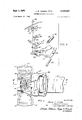
- FIG. 4 is an exploded view of the entire latch assembly, except for the cover and belt, of the present invention.
- FIG. 5 is a sectional view taken on lines VV of FIG. 3 and shows the latch assembly of the present invention
- FIG. 6 is a bottom plan View of the latch assembly of the present invention.
- FIG. 7 is a sectional view of the latch assembly of the present invention taken on lines VII-VII of FIG. 6.
- FIG. 1 shows a typical and pertinent setting for the apparatus of the present invention, viz, an automobile body 11, a passenger 13 on seat 15 inside the body 11.
- the passenger is constrained by safety lap belt segments 17 and 17' (which are buckled together at 19) and harness belt 21 attached at one end to the automobile frame, body, or pillar, as shown at 23 somewhat above and behind the passengers head.
- the harness belt 21 is attached at its lower end 25 to one side of the lap belt 17.
- a retractor as is now known to the art, might be employed.
- FIG. 2 shows the relative positions of the latch assembly 27 and attached harness belt 21, with respect to the anchor member 29 and attached lap belt portions 17 and 17.
- the swivel post 31 is shown disposed in the irregular slot 33 on latch plate 36.
- the jaws 35 are mounted to the latch plate 36 underneath the spring plate 37, the rivets 39 serving to connect both the spring plate and snap jaws to the latch plate, as well as provide pivot points for each of the jaws 35.
- the swivel post 31 is about to be received by the jaws 35, subsequent to their opening as shown in phantom line in FIG. 3.
- the jaws are opened by pressing manually inwardly, i.e. squeezing, the finger levers or press portions 41 at the extremities of the cross over arms 43 which extend up and then across from each of the jaws 35.
- the squeezed position is shown in phantom line in FIG. 3, as is the resultant opened position of the jaws 35.
- the corresponding swivel post position In conjunction with this open jaw position is shown, also in phantom line, the corresponding swivel post position.
- the post 31 is depicted closer to the narrow slot end than in FIG. 2.
- the latch plate is rigidly attached to the lap belt portions 17 and 17' via the 'base plate 45, and therefore all these structures also shown in an intermediate position, in phantom line.
- FIG. 3 shows three sequential positions of the latch structure relative to the swivel post 31 on the lap belt anchor assembly.
- FIG. 2 shows the swivel post 31 inserted into the wider end of latch slot 33, and just approaching the closed jaws 35.
- FIG. 3 the phantom line position shows the swivel post 31 passing through the opened jaws 35
- the heavy lines in FIG. 3 show the swivel post 31 locked between the reclosed jaws 35, and the finger levers 41 spread back out to their normal position.
- This sequence substantially describes the operation of the preferred embodiment.
- FIG. 4 shows an exploded view of all the parts of the latch assembly only, without its cover 47, or the harness belt 21.
- the harness may be seen in FIG. 3 to be connected to the latch plate 36 via looped connection about the knurl bar 49.
- the knurl bar is slot connected across the irregular belt slot 51 and retained therein by retainer pin 52.
- Belt friction and fraying at the end 53 of belt slot 51, is minimized by the slip lip 55 which is press clipped over the edge 53, as shown in the section view of FIG. 5.
- Rivets 39 connect the spring clip 37 to the latch plate 36 with the snap jaws 35 sandwiched therebetween. Each jaw pivots on one of the rivets 39.
- the leaf spring 57 is fastened to the spring clip 37 between the lower pinch tabs 59 and upper tab 60.
- FIG. 4 the leaf spring is shown in its unrestrained, straightened configuration, but under assembly the leaf spring is bowed into a loaded condition between the finger levers 41 of the cross over arms 43 (see FIGS. 2 and 6).
- the ear portions of spring clip 37 extend into the space between the jaw 35 and cross over arm 43 and abut against the inner face of the riser portion 66, of the arm 43. This abutment serves to delimit the extent of inward swing of the jaws toward the closed position.
- the inward closure of the jaws 35 is arrested in the position shown in FIG. 2, so that a slight opening always is present to facilitate insertion of the swivel post 31.
- the post is completely engaged in the narrow, or swivel, end of slot 33, and encircled by the jaws 35, it is constrained from slipping out of the slot by the groove 67 which extends circumferentially around the post 31.
- the jaw 35 locks into the groove 67 and restrains the swivel post from axial displacement out of the latch slot.
- the pin 31 may drop down and out from the slot 33, thereby effecting a disconnect between the harness belt latch assembly and lap belt anchor member.
- the jaws although retaining the pin 31 in the slot 33, do not transmit tension forces between the harness belt and the lap belt; rather such forces are transmitted directly from the post 31 to the swivel end portion of the slot 33, against which the post bears under harness tension.
- the belt force is transmitted through the post as a shearing force normal to the post axis, while the restraint against post disengagement is a tensile force in the post, transmitted from the jaws at the post groove.
- This latter tensile force is independent of the shearing force from impact loading,,and is generally much lesser in magnitude.
- a special leaf spring to jaw lever engagement is effected by a channelform portion 71 of the finger lever, seen in FIGS. 6 and 7.
- the lea-f spring 57 is not directly connected to the jaw arms 43, but rather guidably slides with respect thereto in the channels 71, all the while urging the jaw arms outwardly to close the jaws 35.
- This sliding contact delivers smoother, easier operation of the jaws, with less manual exertion.
- the ends of the leaf spring riveted or otherwise fixed to the levers 41 excessive bowing stresses would be generated in the spring, upon fiexure thereof during jaw operation. These increased stresses would lead to increased spring fatigue, earlier spring failure, and earlier reduction of the spring coefiicient.
- special irregular, concentrated stresses would occur at the point of fastening the spring to the arm. It is apparent that the novel, channel sliding engagement provides a greatly improved and longer lived spring mechanism.
- the entire apparatus works easily and quicky under the influence of one hand only, and may be connected or disconnected with rapidity. Yet, the apparatus will transmit extreme tensile forces between the shoulder belt and lap belt without disconnecting except when actuated to do so.
- the latch mechanism swivels easily and freely on the anchor structure, so that the harness belt easily swings on the lap belt to the angular orientation appropriate for untwisted extension to its connection point on the automobile frame or body, near the occupants head.
- a quickly connectable and disconnectable swivel union for joining at least two separable structures comprising:
- an anchor unit including a base plate member
- a swivel post secured to said base and provided with a circumferential groove spaced from said base plate
- a swivelling latch assembly including a. latch frame with an elongate slot formed therein having a swivel end dimensioned to guidably receive and seat said swivel post,
- resilient means normally retaining said jaws closed in said circumferential groove, and release means for manually urging said jaws open to release said swivel post from said slot.
- a swivelling connector for joining one end of the should belt to the lap belt, comprising:
- an anchor unit having a base plate portion securely fixed to said lap belt
- a swivel post projecting from said plate and defining a circumferential groove spaced from said plate;
- a swivellin g latch mechanism including a latch frame connected to said one end of said shoulder belt, and formed with an elongate slot portion having a swivel end dimensioned to guidably, shearingly, seat said swivel post,
- each of said cross over arms includes a channelform portion into which one end of said leaf spring is slideably seated, to bowedly bear outwardly against the bottom of said channel and thereby hold said arms open and jaws closed.
- said means for connecting said base to said lap belt is a pair of end slots in opposite ends of said base plate, through each of which a loose end of said lap belt is looped and stitched.
- a quickly connectable and disconnectable swivel union for joining separable structures comprising:
- an anchor unit attached to one of said separable structures and having an upstanding swivel post portion with a circumferential groove formed thereon, intermediate the ends thereof;
- a swivelling latch assembly including a latch frame with an elongate slot having a swivel end formed therein as a shear transmitting seat for said swivel post,
- post retention means on said frame, adjacent said swivel end of said slot, and normally projecting into said groove and engaging said post, thereby to maintain said post in engagement with said shear transmitting seat and to arrest axial post,
Landscapes
- Buckles (AREA)
- Automotive Seat Belt Assembly (AREA)
Applications Claiming Priority (1)
| Application Number | Priority Date | Filing Date | Title |
|---|---|---|---|
| US71284068A | 1968-03-13 | 1968-03-13 |
Publications (1)
| Publication Number | Publication Date |
|---|---|
| US3526432A true US3526432A (en) | 1970-09-01 |
Family
ID=24863775
Family Applications (1)
| Application Number | Title | Priority Date | Filing Date |
|---|---|---|---|
| US712840A Expired - Lifetime US3526432A (en) | 1968-03-13 | 1968-03-13 | Swivelling belt connector |
Country Status (5)
| Country | Link |
|---|---|
| US (1) | US3526432A (cg-RX-API-DMAC7.html) |
| JP (1) | JPS4918366B1 (cg-RX-API-DMAC7.html) |
| DE (1) | DE1911872A1 (cg-RX-API-DMAC7.html) |
| FR (1) | FR2003764A1 (cg-RX-API-DMAC7.html) |
| GB (1) | GB1189967A (cg-RX-API-DMAC7.html) |
Cited By (8)
| Publication number | Priority date | Publication date | Assignee | Title |
|---|---|---|---|---|
| US3682498A (en) * | 1970-02-21 | 1972-08-08 | Edith Rutzki | Safety belts |
| US3796461A (en) * | 1971-09-29 | 1974-03-12 | Robbins J Seat Belt Co | Quick disconnect seat belt tongue |
| US4786078A (en) * | 1987-06-22 | 1988-11-22 | Schreier Steven E | Shoulder belt adjuster |
| USD313338S (en) | 1987-10-09 | 1991-01-01 | Recreation Systems, Inc. | Camper tie down holder |
| US5522404A (en) * | 1992-12-22 | 1996-06-04 | Williams; Rick | Adjustable safety and assistance harnessing devices |
| USD772105S1 (en) * | 2015-09-25 | 2016-11-22 | Standard Car Truck Company | Auto rack railroad car restraint clip |
| US10897964B1 (en) | 2019-07-02 | 2021-01-26 | Intertek Industrial Corporation | Adjustable connectors for use with webbing of patient harness systems and other types of safety belt systems |
| US11246379B2 (en) | 2019-07-02 | 2022-02-15 | Intertek Industrial Corporation | Adjustable connectors for use with webbing of patient harness systems and other types of safety belt systems |
Families Citing this family (1)
| Publication number | Priority date | Publication date | Assignee | Title |
|---|---|---|---|---|
| JPS52114062U (cg-RX-API-DMAC7.html) * | 1976-02-25 | 1977-08-30 |
Citations (15)
| Publication number | Priority date | Publication date | Assignee | Title |
|---|---|---|---|---|
| US393400A (en) * | 1888-11-27 | Eliel l | ||
| US438009A (en) * | 1890-10-07 | Joseph a | ||
| US493719A (en) * | 1893-03-21 | hendebson | ||
| US928367A (en) * | 1909-01-16 | 1909-07-20 | Clinton C De Witt | Wire-rope clamp. |
| US1178135A (en) * | 1914-01-06 | 1916-04-04 | Marcus Ray Cowell | Connecting device. |
| US1247258A (en) * | 1917-03-02 | 1917-11-20 | Nicholas P Geisert | Separable fastener. |
| US1384962A (en) * | 1921-07-19 | T ktjhne | ||
| US2059456A (en) * | 1934-05-19 | 1936-11-03 | Hodges Frederick James | Insulator clamp |
| US2348100A (en) * | 1940-10-24 | 1944-05-02 | George B Wadsworth | Splicing device for electrical conductors |
| US2446951A (en) * | 1945-10-31 | 1948-08-10 | Quilter John Raymond Cuthbert | Disconnectible push coupling |
| US2695770A (en) * | 1948-11-12 | 1954-11-30 | Byron Jackson Co | Deadline stabilizer |
| DE1181508B (de) * | 1960-06-28 | 1964-11-12 | Spinnfaser Ag | Verbindung fuer verhaeltnismaessig steife Schlaeuche aus Gummi oder Kunststoff |
| US3378301A (en) * | 1967-03-06 | 1968-04-16 | American Safety Equip | Shoulder strap-lap belt buckle connector |
| US3397431A (en) * | 1967-05-12 | 1968-08-20 | Hydro Craft Inc | Tube clamp assembly |
| US3406433A (en) * | 1967-01-05 | 1968-10-22 | Ford Motor Co | Seat belt coupling device |
-
1968
- 1968-03-13 US US712840A patent/US3526432A/en not_active Expired - Lifetime
-
1969
- 1969-03-08 DE DE19691911872 patent/DE1911872A1/de not_active Withdrawn
- 1969-03-10 FR FR6906595A patent/FR2003764A1/fr not_active Withdrawn
- 1969-03-12 GB GB02962/69A patent/GB1189967A/en not_active Expired
- 1969-03-13 JP JP44018823A patent/JPS4918366B1/ja active Pending
Patent Citations (15)
| Publication number | Priority date | Publication date | Assignee | Title |
|---|---|---|---|---|
| US1384962A (en) * | 1921-07-19 | T ktjhne | ||
| US438009A (en) * | 1890-10-07 | Joseph a | ||
| US493719A (en) * | 1893-03-21 | hendebson | ||
| US393400A (en) * | 1888-11-27 | Eliel l | ||
| US928367A (en) * | 1909-01-16 | 1909-07-20 | Clinton C De Witt | Wire-rope clamp. |
| US1178135A (en) * | 1914-01-06 | 1916-04-04 | Marcus Ray Cowell | Connecting device. |
| US1247258A (en) * | 1917-03-02 | 1917-11-20 | Nicholas P Geisert | Separable fastener. |
| US2059456A (en) * | 1934-05-19 | 1936-11-03 | Hodges Frederick James | Insulator clamp |
| US2348100A (en) * | 1940-10-24 | 1944-05-02 | George B Wadsworth | Splicing device for electrical conductors |
| US2446951A (en) * | 1945-10-31 | 1948-08-10 | Quilter John Raymond Cuthbert | Disconnectible push coupling |
| US2695770A (en) * | 1948-11-12 | 1954-11-30 | Byron Jackson Co | Deadline stabilizer |
| DE1181508B (de) * | 1960-06-28 | 1964-11-12 | Spinnfaser Ag | Verbindung fuer verhaeltnismaessig steife Schlaeuche aus Gummi oder Kunststoff |
| US3406433A (en) * | 1967-01-05 | 1968-10-22 | Ford Motor Co | Seat belt coupling device |
| US3378301A (en) * | 1967-03-06 | 1968-04-16 | American Safety Equip | Shoulder strap-lap belt buckle connector |
| US3397431A (en) * | 1967-05-12 | 1968-08-20 | Hydro Craft Inc | Tube clamp assembly |
Cited By (8)
| Publication number | Priority date | Publication date | Assignee | Title |
|---|---|---|---|---|
| US3682498A (en) * | 1970-02-21 | 1972-08-08 | Edith Rutzki | Safety belts |
| US3796461A (en) * | 1971-09-29 | 1974-03-12 | Robbins J Seat Belt Co | Quick disconnect seat belt tongue |
| US4786078A (en) * | 1987-06-22 | 1988-11-22 | Schreier Steven E | Shoulder belt adjuster |
| USD313338S (en) | 1987-10-09 | 1991-01-01 | Recreation Systems, Inc. | Camper tie down holder |
| US5522404A (en) * | 1992-12-22 | 1996-06-04 | Williams; Rick | Adjustable safety and assistance harnessing devices |
| USD772105S1 (en) * | 2015-09-25 | 2016-11-22 | Standard Car Truck Company | Auto rack railroad car restraint clip |
| US10897964B1 (en) | 2019-07-02 | 2021-01-26 | Intertek Industrial Corporation | Adjustable connectors for use with webbing of patient harness systems and other types of safety belt systems |
| US11246379B2 (en) | 2019-07-02 | 2022-02-15 | Intertek Industrial Corporation | Adjustable connectors for use with webbing of patient harness systems and other types of safety belt systems |
Also Published As
| Publication number | Publication date |
|---|---|
| DE1911872A1 (de) | 1970-05-06 |
| FR2003764A1 (cg-RX-API-DMAC7.html) | 1969-11-14 |
| JPS4918366B1 (cg-RX-API-DMAC7.html) | 1974-05-09 |
| GB1189967A (en) | 1970-04-29 |
Similar Documents
| Publication | Publication Date | Title |
|---|---|---|
| US2893088A (en) | Safety belt buckle | |
| US3526432A (en) | Swivelling belt connector | |
| US3898715A (en) | Fitting for adjusting a safety belt | |
| US3790209A (en) | Non-detachable snap-lock connector for combination shoulder and lap safety harness | |
| US3865397A (en) | Vehicle safety belt systems | |
| GB2116624A (en) | Releasable connector | |
| US2836868A (en) | Safety strap buckle | |
| CN108068670A (zh) | 儿童安全座椅 | |
| US3510151A (en) | Latch for a three-point safety belt for motor vehicles | |
| US1298615A (en) | Safety apparatus for aviators. | |
| CN110712615A (zh) | 织带高度调整装置 | |
| US5024391A (en) | Retractor with auxiliary braking mechanism | |
| US2896284A (en) | Safety belt and buckle structure | |
| JPH085357B2 (ja) | 締付装置 | |
| US3298739A (en) | Seat belt safety apparatus | |
| US4394036A (en) | Passive safety belt arrangement | |
| US4118053A (en) | Safety belt device with a winder/unwinder especially for automobiles | |
| US3132898A (en) | Impact absorbing seat belt | |
| EP1896302A1 (en) | Belt tension indicator | |
| US5454613A (en) | Automatic locking device for an auxiliary seat | |
| US4319667A (en) | Locking device for seatbelt systems | |
| US4193614A (en) | Passive restraining belt for seated vehicle occupant | |
| EP3707033A1 (en) | Emergency device for the quick release of safety belts for vehicles | |
| KR200147500Y1 (ko) | 꼬임방지용 텅플레이트 | |
| CN115303148A (zh) | 车辆座椅碰撞保护装置和车辆座椅 |
Legal Events
| Date | Code | Title | Description |
|---|---|---|---|
| AS | Assignment |
Owner name: TRW AUTOMOTIVE PRODUCTS, INC. EUCLID OHIO 44117 A Free format text: ASSIGNMENT OF ASSIGNORS INTEREST.;ASSIGNOR:FIRESTONE TIRE & RUBBER COMPANY;REEL/FRAME:004296/0155 Effective date: 19840629 |