US3439733A - Foundry molding machine - Google Patents
Foundry molding machine Download PDFInfo
- Publication number
- US3439733A US3439733A US516634A US3439733DA US3439733A US 3439733 A US3439733 A US 3439733A US 516634 A US516634 A US 516634A US 3439733D A US3439733D A US 3439733DA US 3439733 A US3439733 A US 3439733A
- Authority
- US
- United States
- Prior art keywords
- box
- core
- sand
- reservoir
- core box
- Prior art date
- Legal status (The legal status is an assumption and is not a legal conclusion. Google has not performed a legal analysis and makes no representation as to the accuracy of the status listed.)
- Expired - Lifetime
Links
- 238000000465 moulding Methods 0.000 title description 13
- 239000004576 sand Substances 0.000 description 32
- 239000011347 resin Substances 0.000 description 22
- 229920005989 resin Polymers 0.000 description 22
- 239000000203 mixture Substances 0.000 description 14
- 239000000463 material Substances 0.000 description 13
- 238000007664 blowing Methods 0.000 description 10
- 238000000034 method Methods 0.000 description 10
- 239000003054 catalyst Substances 0.000 description 9
- 239000007787 solid Substances 0.000 description 8
- 239000007789 gas Substances 0.000 description 7
- 238000001723 curing Methods 0.000 description 6
- 238000010438 heat treatment Methods 0.000 description 6
- 239000012466 permeate Substances 0.000 description 6
- XAGFODPZIPBFFR-UHFFFAOYSA-N aluminium Chemical group [Al] XAGFODPZIPBFFR-UHFFFAOYSA-N 0.000 description 5
- 229910052782 aluminium Inorganic materials 0.000 description 5
- 125000006850 spacer group Chemical group 0.000 description 5
- NBIIXXVUZAFLBC-UHFFFAOYSA-N Phosphoric acid Chemical compound OP(O)(O)=O NBIIXXVUZAFLBC-UHFFFAOYSA-N 0.000 description 4
- 230000000712 assembly Effects 0.000 description 4
- 238000000429 assembly Methods 0.000 description 4
- 238000001816 cooling Methods 0.000 description 4
- 230000033001 locomotion Effects 0.000 description 4
- 238000004519 manufacturing process Methods 0.000 description 4
- NJPPVKZQTLUDBO-UHFFFAOYSA-N novaluron Chemical compound C1=C(Cl)C(OC(F)(F)C(OC(F)(F)F)F)=CC=C1NC(=O)NC(=O)C1=C(F)C=CC=C1F NJPPVKZQTLUDBO-UHFFFAOYSA-N 0.000 description 4
- 239000002253 acid Substances 0.000 description 3
- 238000010276 construction Methods 0.000 description 3
- 238000010586 diagram Methods 0.000 description 3
- 238000007789 sealing Methods 0.000 description 3
- XLYOFNOQVPJJNP-UHFFFAOYSA-N water Substances O XLYOFNOQVPJJNP-UHFFFAOYSA-N 0.000 description 3
- 229910001018 Cast iron Inorganic materials 0.000 description 2
- 239000003638 chemical reducing agent Substances 0.000 description 2
- 239000000446 fuel Substances 0.000 description 2
- XPFVYQJUAUNWIW-UHFFFAOYSA-N furfuryl alcohol Chemical compound OCC1=CC=CO1 XPFVYQJUAUNWIW-UHFFFAOYSA-N 0.000 description 2
- 238000013007 heat curing Methods 0.000 description 2
- 238000002156 mixing Methods 0.000 description 2
- 230000002093 peripheral effect Effects 0.000 description 2
- 235000011007 phosphoric acid Nutrition 0.000 description 2
- 229920001807 Urea-formaldehyde Polymers 0.000 description 1
- 239000003377 acid catalyst Substances 0.000 description 1
- GZCGUPFRVQAUEE-SLPGGIOYSA-N aldehydo-D-glucose Chemical compound OC[C@@H](O)[C@@H](O)[C@H](O)[C@@H](O)C=O GZCGUPFRVQAUEE-SLPGGIOYSA-N 0.000 description 1
- 229910000147 aluminium phosphate Inorganic materials 0.000 description 1
- 239000011230 binding agent Substances 0.000 description 1
- 230000005540 biological transmission Effects 0.000 description 1
- 239000004202 carbamide Substances 0.000 description 1
- 238000006555 catalytic reaction Methods 0.000 description 1
- 238000004891 communication Methods 0.000 description 1
- 230000002939 deleterious effect Effects 0.000 description 1
- 238000009429 electrical wiring Methods 0.000 description 1
- 230000005611 electricity Effects 0.000 description 1
- 230000003028 elevating effect Effects 0.000 description 1
- 238000005265 energy consumption Methods 0.000 description 1
- 230000010006 flight Effects 0.000 description 1
- 239000007849 furan resin Substances 0.000 description 1
- 239000011810 insulating material Substances 0.000 description 1
- 239000007788 liquid Substances 0.000 description 1
- 238000012423 maintenance Methods 0.000 description 1
- 238000005192 partition Methods 0.000 description 1
- 239000000843 powder Substances 0.000 description 1
- 239000000047 product Substances 0.000 description 1
- 238000004904 shortening Methods 0.000 description 1
- 239000011973 solid acid Substances 0.000 description 1
- 239000000126 substance Substances 0.000 description 1
Images
Classifications
-
- B—PERFORMING OPERATIONS; TRANSPORTING
- B22—CASTING; POWDER METALLURGY
- B22C—FOUNDRY MOULDING
- B22C9/00—Moulds or cores; Moulding processes
- B22C9/12—Treating moulds or cores, e.g. drying, hardening
-
- B—PERFORMING OPERATIONS; TRANSPORTING
- B22—CASTING; POWDER METALLURGY
- B22C—FOUNDRY MOULDING
- B22C15/00—Moulding machines characterised by the compacting mechanism; Accessories therefor
- B22C15/23—Compacting by gas pressure or vacuum
- B22C15/24—Compacting by gas pressure or vacuum involving blowing devices in which the mould material is supplied in the form of loose particles
Definitions
- gas burners are generally employed producing a flame which impinges directly on the core or mold box. These machines work at curing or heating temperatures in the range of approximately 600 to 700 F. If one of these many burners employed is not functioning properly, the heating of the box will be uneven and the box may shrink or distort causing the production of inaccurate cores or molds, broken cores or molds, or improperly cured cores. Moreover, such systems generally shorten the life of the expensive patterns or boxes employed.
- One of the most economical and easily workable materials which can be employed for a core box is aluminum, but which cannot be subjected to such extreme temperatures and produce continually accurate molds or cores. Moreover, long cure times are still required since the high temperatures simply transfer the heat from the heated box inwardly to the interior of the core or mold.
- Another principal object is the provision of a foundry mold or core making machine of simplified construction not requiring high maintenance and fuel cost for the production of molds or cores.
- Still another object is the provision of a machine and method for the curing of molds or cores at a temperature which makes it possible to use low temperature materials, such as aluminum, in the construction of the mold or core box which maintain their strength and will not distort in such temperature range. Moreover, materials such as the aforementioned aluminum can conduct heat about 4.5 times faster than cast iron, for example.
- Yet another object is the provision of a core or mold making machine not requiring water cooled sand-resin reservoirs which are employed to prevent the resins from reacting before entering the forming box. Needless to say, these cooling systems are expensive to build and maintain.
- the object again is a simplified machine having the above-noted advantages.
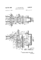
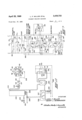
- FIG. 1 is a side elevation of a machine in accordance with the present invention
- FIG. 2 is an end elevation of the machine shown in FIG. 1 as seen from the right thereof;
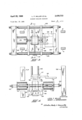
- FIG. 3 is an enlarged horizontal section taken substantially on the line 33 of FIG. 1 illustrating in detail the core box opening and closing mechanism of the machine;
- FIG. 4 is a front elevation of the mechanism illustrated in FIG. 3 as seen from the bottom of such view;
- FIG. 5 is a fragmentary vertical section taken substantially on the line 5-5 of FIG. 3 with the core box opened;
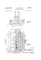
- FIG. 6 is an enlarged fragmentary vertical section taken substantially on the line 6-6 of FIG. 1 showing the sand-resin mix reservoir and the power driven agitator disposed therewithin;
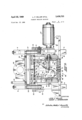
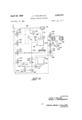
- FIG' 7 is a schematic electrical wiring diagram illustrating the cycle of operation of the illustrated machine embodiment
- FIG. 8 is a schematic pneumatic piping diagram illustrating perhaps more clearly the operating components of the illustrated machine
- FIG. 9 is an enlarged fragmentary vertical section of an exemplary core box illustrating the vents for the sand blowing operation which are also utilized as ports for the admission of the hot air to permeate the blown core;
- FIG. 10 is a schematic piping diagram illustrating the mechanism for heating the air and supplying the same to the core box.
- the illustrated machine may include a base 1 having mounted thereon a bottom frame 2 upwardly from which extend four corner frame .posts 3, 4, 5 and 6.
- a top frame 7 is supported thereon and includes two main horizontal beams 8 and 9.
- two cylindrical hoppers 10 and 11 At the righthand side of the machine as seen in FIG. 1 there is provided two cylindrical hoppers 10 and 11, side-by-side, which may be supplied from an overhead conveyor system with a sand-resin mix, and a sand-catalyst mix, respectively.
- a rotating circular table as indicated at 12 and 13 which may be driven by the motors 14 and 15 through the transmissions 17 and 18, respectively.
- Posts 19 and 20 support ploughs 21 and 22, respectively, extending radially of the rotating table and such are effective to plough material falling onto the tables from the hoppers off into a funnel 23 positioned therebeneath.
- the bottom of the funnel will be closed .by a slide cut-off plate 24.
- the speed of the motors 14 and 15 will control the amount of materiel fed from the respective hoppers 10 and 11, and thus may actively control the proportion of resin and catalyst in the mix being dumped into the hopper 23.
- Other blending or mixing devices may, of course, be employed for supplying the machine with the properly blended sandresin mix.
- the beams 8 and 9 are each provided with a pair of depending rods as shown at 26 and 27.
- Such rods may be secured to the beams by the fasteners shown, and the lower ends of such rods are provided with laterally projecting axles as shown at 28 and 29 on which are journalled flanged rollers 30 and 31, respectively.
- Horizontal rails 32 and 33 ride on the flanged rollers thus supported on the bottom of the rods suspended from the beams 8 and 9.
- a pair of transverse frame members 34 and 35 extending between the rails 32 and 33 support a sand-mix blow reservoir shown generally at 36.
- piston-cylinder assembly 37 Reciprocation of the reservoir on the tops of the rollers 30 and 31 is obtained by the piston-cylinder assembly 37, the rod 38 of which is connected to the reservoir at 39.
- pistoncylinder assembly 37 may be mounted on a support plate or bracket 40 extending between the frame legs 5 and 6 of the machine as seen more clearly in FIG. 2.
- a blowhead shown generally at 42 in FIG. 1 is mounted on the top frame 7 and is provided with a blow valve 43.
- the details of the blowhead and valve are shown more clearly in FIG. 6.
- the blowhead 42 includes a main inlet passage 44 from the blow-valve 43 leading to the main horizontal passage 45.
- the blowhead includes two laterally spaced blow inlets 46 and 47 communicating with the horizontal passage 45.
- a tapped aperture in the blowhead may be provided with plug 48 as indicated while on the opposite side of the blowhead a pipe 49 is threaded into a similar tapped aperture and may lead to a pre-fill valve.
- Each of the inlet ports 46 and 47 may be provided in conventional manner with a resiliently deformable peripheral sealing ring as indicated at 50.
- an exhaust port 51 Centrally disposed between the inlet ports is an exhaust port 51 also provided with a peripheral sealing ring 52 and a sand retaining screen 53 which may be held in place by a centrall disposed fastener 54.
- the port 51 communicates with horizontal passages 55 leading to exhaust valve 56 shown in FIG. 1.
- piston-cylinder assembly 37 which is operative to recriprocate or shuttle the reservoir 36 will alternately position such reservoir beneath the hopper 23 and beneath the blowhead 42 to be clamped thereagainst by the core box therebeneath by means of the vertically movable table 58 and the clamp cylinder 59 in the base of the machine.
- the reservoir 36 comprises a cylinder 60 which is closed at each end by closure members 61 and 62 which are sealed thereto by means of the O-rings indicated at 63 and 64.
- the end closures are held in place by fasteners 65.
- the top of the cylinder 60 is provided with a large diameter vertically extending fill-opening 66, the top of which is provided with a ring 67 sealed by O-rinvg 68 to the flange 69.
- the end closures 61 and 62 are provided with vertically extending passages 70 and 71 which in the blow position of the resenvoir 36 are aligned with the air inlet openings 46 and 47, respectively.
- Such passages 70 and 71 enter the interior of the reservoir behind annular deflector plates 72 and 73 secured to the interior of the closures within the cylinder 60' by fasteners 74.
- the deflectors are provided with a slight clearance with the interior of the cylinder 60 as indicated at 75.
- the bottom of the cylinder 60 is provided with a discharge port or opening 77 having a flaring mouth 78.
- the passage 77 is provided in a port member 79 which may be threaded into the bottom of the cylinder 60 as well as the support plate 80'.
- the port members fits within a bottom or blow-plate 81 which may be provided with vent openings as indicated at 82.
- Journalled in the closure 62 is the shaft 85 of agitator 86 which is driven by motor 87.
- the shaft is driven by a flanged speed reducer 88 secured to the outer side of the closure 62 by fasteners 89 and the totally enclosed motor 87 is mounted directly on the speed reducer.
- the agitator 86 secured to the end of the shaft 85 includes a diametral or transverse bar 90 with helical opposite hand blades 91 and 92 extending from the opposite ends thereof.
- the helical blades fit closely adjacent the interior of the cylinder 60 and rotation of the shaft 85 in the direction of the arrow 93 will move the material within the reservoir in the directions of the arrows 94 and 95 or centrally toward the discharge opening 77 and away from the annular air inlets at the opposite ends of the cylinder.
- the sand mix may be dumped into the reservoir in the position beneath the hopper 23 when the piston-cylinder assembly 37 is retracted.
- the extension of the piston-cylinder assembly 37 will then move the reservoir to the position shown in FIGS. 1 and 6, and elevation of the table 58 will then move the core box upwardly against the bottom of the blow-plate 81 to cause the entire reservoir to elevate sealing the respective inlet and discharge passages.
- air will be admitted from the blowvalve 43 causing the sand within the reservoir to fluff up or fluidize and be discharged through the mouth 78 of the port 71. Shortly thereafter the air pressure is exhausted through the ports 55 to the exhaust valve 56.
- the core box is then unclamped from the reservoir for the cure cycle, and the reservoir is then returned to the fill position.
- the core box into which the material is blown through the port 77 may comprise two laterally separable halves 9'8 and 99, the interior of Which may be patterned to form, for example, a worm gear housing core.
- the core box halves are mounted on the rods of piston-cylinder assemblies 101 and 102, and it can be seen that extension of the assemblies will close the core box while retraction will open the same for stripping of the core therefrom.
- piston-cylinder assemblies are supported on transverse frame members 10 3 and 104 which are interconnected by rods 105 and 106.
- the rods 105 and 106 are supported on brackets 107 and 108 on the table 58 so that the entire core box opening and closing mechanism moves vertically with the table.
- the table 58 may be provided with a slot 111 in which is mounted a hot air pedestal 112 having an upwardly projecting core lightener 113 thereon as indicated in FIG. 3, and a handle 114 may be connected to the pedestal.
- the details of the core box are shown more clearly in FIG. 9 hereinafter described.
- a bracket 116 Attached to the blow-plate 81 and horizontally movable therewith is a bracket 116 on which is mounted a vertically extending heat cure spacer shown generally at 117.
- spacer includes a pad 118 on the bottom thereof having a laterally directed exhaust port 119 therein.
- Post 120 Vertically projecting upwardly from the spacer 117 are four posts 120 which will underlie the blowhead 42 when the piston-cylinder assembly 37 is retracted.
- the core box half 99 includes a core box mounting plate '122 on which the patterned interior 123 of the box is secured.
- the patterned portion 123 of the box may include a central horizontal partition 124 dividing the interiorinto two chambers 125 and 1-26.
- Screened vent openings 127 are po sitioned throughout the patterned portion of the core box communicating with the chambers 125 and 126. The arrangement and size of such vents is, of course, designed to obtain a properly compacted blown sand article within the box.
- a heater mounting plate 130 Secured to the exterior of the core box mounting plate is a heater mounting plate 130 which has positioned therein ring heaters of the electrical type shown at 131 and 132.
- the somewhat larger ring heater 131 may, for example, be an 1800 watt-1'20 volt heater, while the smaller heater 132 may be 750 watts-120 volts.
- a plate 133 of insulating material is interposed between the heater mounting plate 130 and the mounting plate 134 for the core box clamps which will move the core box halves 98 and 99 laterally to open same and firmly press them together for the clamped blow cure position.
- the lightener 113 is provided with a vertical passage 136 and has a plurality of radially extending screened ports 137 as well as a top screened port 13 8 providing communication between the vertical passage and the inte-rior of the core box.
- the vertical passage 1 36 at its lower end communicates with passage 139 in the hot air pedestal 112.
- the core box halves will be clamped together and the table 58 will be elevated to clamp the thus formed core box directly beneath the blow-plate 81, and the sand-resin mix will be blown through the port 77 into the top opening 140 of the core box, and the screened vents '52 in the blow-plate will serve to vent the upper end of the core.
- the air passes through the screened vents into the chambers 125 and 12-6 in each core box half and is vented therefrom through ports 141 and 142 shown in FIG. 9.
- thermocouple 14 5 is located in the passage 139 of the hot air pedestal 112 to measure the temperature ofthe air therein, and a thermocouple 146 may be located in the wall of the core box to measure the box temperature.
- FIGS. 7 and '8 there is illustrated one of a wide variety of control systems which may be employed to operate the illustrated machine.
- a start push button 150 may be employed to energize relay 151 to close switches 152, 153, 154 and 1'55.
- the switch 152 energizes horizontal clamp solenoid 156 shifting valve 157 seen in FIG. 8 supplying pneumatic pressure from line 158 to the blind ends of the 7 clamp piston-cylinder assemblies 101 and 102, causing the core box to clamp closed.
- the closing of switch contacts 153 energizes fill solenoid 160 through manually operated selector switch 161 to shift valves 162 supplying pneumatic pressure to the blind end of the carriage cylinder 37, shifting the reservoir 36 from the fill to the blow position.
- the closing of switch contacts 154 then permits the relay 151 to be de-energized by manual stop push button 163.
- the closing of contacts 155 by the relay 151 will then energize the vertical clamp solenoid 164 when the limit switch 165 is closed.
- the limit switch 165 will be closed by the proper position of the reservoir 36 in registry with the blowhead 42.
- the solenoid 164 shifts valve 166 to supply pressure from the line 158 to the bottom of the clamp cylinder 59 through line 168 having therein check valve 169, flow control valve 170, and shutoff valve 171.
- valve 183 shifts valve 184 in three-quarter inch line 185 to supply air from three inch line 186 to the blowhead through the pre-fill pipe 49 illustrated in FIG. 6.
- This is omrative to force the sand through the discharge opening into the closed core box therebeneath, and simultaneously with the energization of the solenoid 182, pre-fill timer 188 as well as agitator timer 189 are also energized.
- Relay 190 controlling switch contacts 191 which in turn energize motor 87 driving the agitator.
- the timer 188 will time out at a very short interval and will then energize the blow timer 193 through the line 194.
- blow solenoid 195 shifting valve 196 to open the blow valve 43 connected to the three inch line 186 to ram or pack the sand firmly into the core box.
- the blow time as determined by the timer 193 may be approximately one-quarter of a second, and when the timer 193 thus times out, the solenoid 195 will be deenergized permitting the shuttle valve 197 to open the exhaust valve 56.
- a differential safety valve 200 is connected to the blowhead 42 or sand reservoir 36 by means of a one-quarter inch line 201 and is connected to a three-quarter inch line 203 communicating with lines 168 and 204.
- Pilot operated valve 205 is effective to shift shutoff valve 206 to connect line 204 to cylinder 59 to cause rapid elevation of table 58.
- the relay 208 will be energized through selector switch 209 which in turn closes switch contacts 210 energizing relay 211.
- Relay 211 then closes switch contacts 212 to energize heat timer 213 and heat solenoid 214.
- Heat solenoid 214 shifts valve 215 in turn shifting threeway valve 216.
- the shifting of valve 216 connects heat line 217 to line 218.
- the three-way valve 216 in its normal position connects the line 218 to the exhaust line 219.
- the heat timer 213 may have a maximum time cycle of approximately two and one-half minutes although it will be appreciated that cores may be cured in considerably less time as, for example, approximately twenty to thirty seconds. It is noted that various manual switches may be positioned throughout the circuit such as the heat selector switch 220 and the repeat blow switch 221. At the conclusion of the heat cycle controlled by the setting of the timer 213, the relay 211 may then be employed to de-encrgize or repeat the cycle.
- thermocouple 234 is provided in the line 217 to monitor the temperature of the air leaving the heater 230, and this thermocouple together with the thermocouple 146 measuring the box temperature and the thermocouple 145 measuring the entering air temperature may be connected to a switch box 235 feeding the information thus obtained back to the controller 226 which in turn regulates the air and electrical heater temperatures.
- the operation of the illustrated machine is as follows. Metered amounts of sand are fed from the hoppers and 11 containing, respectively, measured amounts of resin and catalyst into the hopper 23 to drop into the reservoir 36 positioned therebeneath by the retraction of the piston-cylinder assembly 37. With the core box closed by the clamps 101 and 102, the piston-cylinder 37 is then extended to the center line of the machine beneath the blowhead 42. The clamp cylinder 59 is then elevated to elevate the table and the closed core box to clamp the latter against the reservoir 36 in turn to clamp the reservoir 8 to the blowhead. The blow cycle is then initiated and the sand within the reservoir is transported into the core box to be packed firmly therein with air passing from the vents through the lines 218 and 219 to atmosphere.
- the core box and core box clamps still closed, are lowered slightly to permit the reservoir to be retracted to the fill position beneath the hopper 23, and the vertical heat cure spacer 117 is then positioned in the center line of the machine positioning the pad 118 above the top of the core box.
- the core box is then again vertically clamped against the pad 118 and the spacer 117 against the blowhead.
- the three-way valve 216 is now shifted.
- the hot air then passes through the line 218 into the four compartments common to the core box vents through the ports 14-1, 1142, 143 and 144, as well as the port 139 leading to the lightener 113.
- the hot air then passes through the vents and permeates the blown core, and then passes outwardly through the screened port of passage 119 in the pad 1'18.
- the passage 119 may be connected to suitable exhaust fans or the like to be conducted out of the room in which the machine is operating since both moisture and deleterious gases may be included in such exhaust.
- the driving of the moisture from the core has been found to be extremely helpful in accelerating the cure by the method herein disclosed.
- valve 216 is again shifted and the box is then unclamped by the lowering of the table and then unclamped horizontally and the core is then removed manually or automatically.
- the box may then be blown clean, sprayed, and then the reservoir is repositioned in the center line of the machine for a repeat of the above-described cycle.
- the hot air heater 230 may elevate the compressed air temperature from about 85 F. to about 400 F. as measured by the thermocouple 234. The temperature of the air will then drop to about 300 F. or just below that as it enters the core box as measured by the thermocouple 145. The temperature of the core box as maintained by the ring heaters 131 and 132 may be maintained at the desired level throughout the cycle of the machine.
- Resins A200, 122-0, and CR- lSl are commercially available from Archer-Daniels-Midland Company (ADM Chemicals, Foundry Products Division, Cleveland, Ohio).
- Resin A200 is a furfural alcohol base material and is classed as a cold or air set material.
- Resin 122-C is a furfural alcohol urea formaldehyde resin classed as a hot box material, meaning that it is a material with long pot life requiring curing temperatures around 600 degrees Fahrenheit.
- Resin CR-151 is a urea modified phenolic also classed as a hot box material.
- binder materials used would be suitable for either a hot box, warm box, or air set use, depending upon the amount and type of catalyst used.
- the following are typical of some of the acid catalysts that are used:
- bench life of the mixed sand also becomes shorter as the cure time is shortened which requires a machine having a fairly rapid cycle of operation.
- the term bench life may be defined as a time limit within which satisfactory cores can be made after the resin is mixed with the catalyst and sand.
- the cost of core boxes may be reduced since existing hot box systems usually employing furan resins require temperatures in the vicinity of 600 to 700 F. With the present process, requiring temperatures of only about 300 F. It is possible to use low temperature materials in construcing mold and core boxes. Also, in such hot box systems, water cooling is usually required to prevent the resins from reacting before entering the box, and, needless to say, these cooling systems are expensive and difficult to maintain. The less heat required for the present process not only reduces the amount of energy required to form the sand articles, but also enables greater accuracy of the article to be obtained.
- resin-catalyst systems which are used to bond the sand grains together may burn at temperatures in excess of 350 F. during the curing cycle, and accordingly if the temperatures are maintained below 300 F. such burning does not occur.
- Such low temperatures permit the use of aluminum in the construction of the boxes, and since aluminum can conduct heat approximately 4.5 times faster than cast iron, a warm core box may be maintained with little electrical heat energy.
- the Warm core box and the hot air blown or permeated through the core will thus produce accurate cores in a minimal cure time.
- the warm box tends to cure a shell on the sand article while the hot air permeated through the interior of the article cures the inside thereof.
- certain areas of the core are not cured when the core is first removed from the core box, but within minutes the core will be completely cured.
- a core blowing machine comprising a sand-resin mix reservoir having a central discharge opening therein, means to support a core box clamped beneath said sand resin mix reservoir, means to blow sand from said reservoir to such core box through such discharge opening, and means to permeate a low temperature accelerator through such core box substantially to cure the core within the same, said reservoir including a power-driven agitator therein operative to increase the bench life of such sand-resin mix, said agitator being in the form of a screw type conveyor operative to move such mix toward such central discharge opening of said reservoir.
- a foundry molding machine comprising a blowhead, a sand reservoir, means operative to clamp a core box and the like to said reservoir and said reservoir to said head, vent means connected to such box, and means to switch said vent means from exhaust to a source of an accelerator under pressure after sand is blown within such box to cause the same to permeate the sand within such box and accelerate curing of the sand.
- a foundry molding machine as set forth in claim 5 including means to remove said reservoir from such box and to replace the same with a vented pressure pad prior to permeating such accelerator through the box.
- a foundry molding machine as set forth in claim 5 including means operative to heat the box.
- a foundry molding machine as set forth in claim 5 including means operative to fill said reservoir With proportional amounts of sand containing a resin and catalyst.
Landscapes
- Engineering & Computer Science (AREA)
- Mechanical Engineering (AREA)
- Casting Devices For Molds (AREA)
Description
April 1969 L. F. MILLER ETAL 3,439,733
FOUNDRY MOLDING MACHINE Filed Dec. 27, 1965 Sheet of e INVENTORS LEON E MILLER "1 HENRY J. HERBRUGGEN BY awn 7141 0 ATTORNEYS A ril 22, 1969 L. F. MILLER ETAL 3,439,733
FOUNDRY MOLDING MACHINE Filed Dec. 27, 1965 Sheet of e 1 m 8 W 07 i m" i I04 JET .3
I04 l I03 n fa" 101 "\IOS "mm F M :34 I34 INVENTORS L LEON E MILLER g HENRY J. HERBRUG'GEN BY ammd a 0 ATTORNEYS April 22, 9 L. F. MILLER ETAL FOUNDRY MOLDING MACHINE 3 I of 6 Sheet Filed Dec. 27, 1965 n2 hr INVENTORS LEG/V F. M/LLER HENRY J. HERBRUGGE/V dmflmyhydflmwulfi ATTORNEYS April 1969 L. F. MILLER ETAL 3,439,733
FOUNDRY MOLDING MACHINE Filed Dec. 27, 1965 Sheet 4 of e HEN/'7) J. HERBRUGGE/V ATTORNEYS April 22, 1969 L. F. MILLEF: ETAL FOUNDRY MOLDING MACHINE Sheet Filed Dec. 27, 1965 ATTORNEYS On? mm Hula Mm @mm :I. J.
21 mmw mmmA 0 N m: 55 mnmv L H April 22, 1969 L. F. MILLER ETAL 3,439,733
FOUNDRY MOLDING MACHINE Filed Dec. 27, 1965 Sheet 6 of 6 :95; I96: 1 44 I56 J f lh 5 l57 F/K\ A a 1 L91. I g? 4 J l I n g ag, I I 217 d fals fJg. [E7
. INVENTORS LEON F MILLER HENRY J. HERBRUGGEN ATTORNEYS United States Patent 3,439,733 FOUNDRY MOLDING MACHINE Leon F. Miller, Rocky River, and Henry J. Herbruggen, Westlake, Ohio, assignors to The Sherwin-Williams Company, a corporation of Ohio Filed Dec. 27, 1965, Ser. No. 516,634 Int. Cl. B22c 5/08, 7/00, 5/04 U.S. Cl. 164200 9 Claims ABSTRACT OF THE DISCLOSURE This invention relates generally as indicated to a foundry sand forming machine and method and more particularly to a process and machine for producing sand molds or cores by passing hot air therethrough.
In conventional hot box core or mold making machines, gas burners are generally employed producing a flame which impinges directly on the core or mold box. These machines work at curing or heating temperatures in the range of approximately 600 to 700 F. If one of these many burners employed is not functioning properly, the heating of the box will be uneven and the box may shrink or distort causing the production of inaccurate cores or molds, broken cores or molds, or improperly cured cores. Moreover, such systems generally shorten the life of the expensive patterns or boxes employed. One of the most economical and easily workable materials which can be employed for a core box is aluminum, but which cannot be subjected to such extreme temperatures and produce continually accurate molds or cores. Moreover, long cure times are still required since the high temperatures simply transfer the heat from the heated box inwardly to the interior of the core or mold.
Often times conventional hot box machines require special core removal equipment since the high temperatures create poor workingconditions and to cycle at optimum speed, mechanical handling and removal equipment is required. Moreover, special equipment is often required to remove hot moisture containing gases which ordinarily must be carried away from the sand core or mold to obtain the proper cure. Needless to say, such high temperature sand forming systems are costly to construct, operate, and are not the most reliable.
It is accordingly a principal object of the present invention to provide a foundry sand forming machine and a method which will operate at a temperature about 300 F. and yet still produce a mold or core in a relatively short cycle time.
Another principal object is the provision of a foundry mold or core making machine of simplified construction not requiring high maintenance and fuel cost for the production of molds or cores.
Still another object is the provision of a machine and method for the curing of molds or cores at a temperature which makes it possible to use low temperature materials, such as aluminum, in the construction of the mold or core box which maintain their strength and will not distort in such temperature range. Moreover, materials such as the aforementioned aluminum can conduct heat about 4.5 times faster than cast iron, for example.
3,439,733 Patented Apr. 22, 1969 "ice In the resin-catalysis systems, used to bond the sand grains together, burning generally occurs at temperatures in excess of 350 F. during the cure portion of the cycle. This generally produces cores of not the best quality and it can be seen that it is desirable for a variety of reasons to maintain the temperature of the heating medium employed of from about 250 to about 350 F.
With such lower temperatures and, of course, less fuel consumption it is possible to obtain a faster cure time than with the conventional hot box gas flame impinged directly on the mold or core box. This can be accomplished by the combination of a warm core box, which may be heated continually with electrical heating elements, and hot air blown or permeated through the core or mold producing a minimal cure time. The warm box cures a shell on the core while the hot air cures the inside of the core, thus permitting the mold or core to be removed from the machine during a very short cure cycle. It is, therefore, another principal object of the present invention to provide a foundry core or mold making machine and process which will utilize low energy consumption and yet still have rapid cure cycles.
Yet another object is the provision of a core or mold making machine not requiring water cooled sand-resin reservoirs which are employed to prevent the resins from reacting before entering the forming box. Needless to say, these cooling systems are expensive to build and maintain. The object again is a simplified machine having the above-noted advantages.
Other objects and advantages of the present invention will become apparent as the following description proceeds.
To the accomplishment of the foregoing and related ends, the invention, then comprises the features hereinafter fully described and particularly pointed out in the claims, the following description and the annexed drawings setting forth in detail certain illustrative embodiments of the invention, this being indicative, however, of but one of a few of the various ways in which the principles of the invention may be employed.
In said annexed drawings:
FIG. 1 is a side elevation of a machine in accordance with the present invention;
FIG. 2 is an end elevation of the machine shown in FIG. 1 as seen from the right thereof;
FIG. 3 is an enlarged horizontal section taken substantially on the line 33 of FIG. 1 illustrating in detail the core box opening and closing mechanism of the machine;
FIG. 4 is a front elevation of the mechanism illustrated in FIG. 3 as seen from the bottom of such view;
FIG. 5 is a fragmentary vertical section taken substantially on the line 5-5 of FIG. 3 with the core box opened;
FIG. 6 is an enlarged fragmentary vertical section taken substantially on the line 6-6 of FIG. 1 showing the sand-resin mix reservoir and the power driven agitator disposed therewithin;
FIG' 7 is a schematic electrical wiring diagram illustrating the cycle of operation of the illustrated machine embodiment;
FIG. 8 is a schematic pneumatic piping diagram illustrating perhaps more clearly the operating components of the illustrated machine;
FIG. 9 is an enlarged fragmentary vertical section of an exemplary core box illustrating the vents for the sand blowing operation which are also utilized as ports for the admission of the hot air to permeate the blown core; and
FIG. 10 is a schematic piping diagram illustrating the mechanism for heating the air and supplying the same to the core box.
3 MACHINE, GENERAL ARRANGEMENT Referring now to FIGS. 1 through 6 and more particularly to FIGS. 1 and 2, the illustrated machine may include a base 1 having mounted thereon a bottom frame 2 upwardly from which extend four corner frame .posts 3, 4, 5 and 6. A top frame 7 is supported thereon and includes two main horizontal beams 8 and 9. At the righthand side of the machine as seen in FIG. 1 there is provided two cylindrical hoppers 10 and 11, side-by-side, which may be supplied from an overhead conveyor system with a sand-resin mix, and a sand-catalyst mix, respectively. Directly beneath each hopper is a rotating circular table as indicated at 12 and 13 which may be driven by the motors 14 and 15 through the transmissions 17 and 18, respectively. Posts 19 and 20 support ploughs 21 and 22, respectively, extending radially of the rotating table and such are effective to plough material falling onto the tables from the hoppers off into a funnel 23 positioned therebeneath. In the position of the machine shown in FIG. 1 the bottom of the funnel will be closed .by a slide cut-off plate 24. It can thus be understood that the speed of the motors 14 and 15 will control the amount of materiel fed from the respective hoppers 10 and 11, and thus may actively control the proportion of resin and catalyst in the mix being dumped into the hopper 23. Other blending or mixing devices may, of course, be employed for supplying the machine with the properly blended sandresin mix.
Referring now momentarily to FIG. 6, it will be seen that the beams 8 and 9 are each provided with a pair of depending rods as shown at 26 and 27. Such rods may be secured to the beams by the fasteners shown, and the lower ends of such rods are provided with laterally projecting axles as shown at 28 and 29 on which are journalled flanged rollers 30 and 31, respectively. Horizontal rails 32 and 33 ride on the flanged rollers thus supported on the bottom of the rods suspended from the beams 8 and 9. A pair of transverse frame members 34 and 35 extending between the rails 32 and 33 support a sand-mix blow reservoir shown generally at 36. Reciprocation of the reservoir on the tops of the rollers 30 and 31 is obtained by the piston-cylinder assembly 37, the rod 38 of which is connected to the reservoir at 39. Such pistoncylinder assembly 37 may be mounted on a support plate or bracket 40 extending between the frame legs 5 and 6 of the machine as seen more clearly in FIG. 2.
A blowhead shown generally at 42 in FIG. 1 is mounted on the top frame 7 and is provided with a blow valve 43. The details of the blowhead and valve are shown more clearly in FIG. 6. The blowhead 42 includes a main inlet passage 44 from the blow-valve 43 leading to the main horizontal passage 45. The blowhead includes two laterally spaced blow inlets 46 and 47 communicating with the horizontal passage 45. A tapped aperture in the blowhead may be provided with plug 48 as indicated while on the opposite side of the blowhead a pipe 49 is threaded into a similar tapped aperture and may lead to a pre-fill valve. Each of the inlet ports 46 and 47 may be provided in conventional manner with a resiliently deformable peripheral sealing ring as indicated at 50. Centrally disposed between the inlet ports is an exhaust port 51 also provided with a peripheral sealing ring 52 and a sand retaining screen 53 which may be held in place by a centrall disposed fastener 54. The port 51 communicates with horizontal passages 55 leading to exhaust valve 56 shown in FIG. 1.
It can now be seen that the piston-cylinder assembly 37 which is operative to recriprocate or shuttle the reservoir 36 will alternately position such reservoir beneath the hopper 23 and beneath the blowhead 42 to be clamped thereagainst by the core box therebeneath by means of the vertically movable table 58 and the clamp cylinder 59 in the base of the machine.
Referring again to FIG. 6, it will be seen that the reservoir 36 comprises a cylinder 60 which is closed at each end by closure members 61 and 62 which are sealed thereto by means of the O-rings indicated at 63 and 64. The end closures are held in place by fasteners 65. The top of the cylinder 60 is provided with a large diameter vertically extending fill-opening 66, the top of which is provided with a ring 67 sealed by O-rinvg 68 to the flange 69. The end closures 61 and 62 are provided with vertically extending passages 70 and 71 which in the blow position of the resenvoir 36 are aligned with the air inlet openings 46 and 47, respectively. Such passages 70 and 71 enter the interior of the reservoir behind annular deflector plates 72 and 73 secured to the interior of the closures within the cylinder 60' by fasteners 74. The deflectors are provided with a slight clearance with the interior of the cylinder 60 as indicated at 75.
The bottom of the cylinder 60 is provided with a discharge port or opening 77 having a flaring mouth 78. The passage 77 is provided in a port member 79 which may be threaded into the bottom of the cylinder 60 as well as the support plate 80'. The port members -fits within a bottom or blow-plate 81 which may be provided with vent openings as indicated at 82.
Journalled in the closure 62 is the shaft 85 of agitator 86 which is driven by motor 87. The shaft is driven by a flanged speed reducer 88 secured to the outer side of the closure 62 by fasteners 89 and the totally enclosed motor 87 is mounted directly on the speed reducer.
The agitator 86 secured to the end of the shaft 85 includes a diametral or transverse bar 90 with helical opposite hand blades 91 and 92 extending from the opposite ends thereof. The helical blades fit closely adjacent the interior of the cylinder 60 and rotation of the shaft 85 in the direction of the arrow 93 will move the material within the reservoir in the directions of the arrows 94 and 95 or centrally toward the discharge opening 77 and away from the annular air inlets at the opposite ends of the cylinder.
The sand mix may be dumped into the reservoir in the position beneath the hopper 23 when the piston-cylinder assembly 37 is retracted. The extension of the piston-cylinder assembly 37 will then move the reservoir to the position shown in FIGS. 1 and 6, and elevation of the table 58 will then move the core box upwardly against the bottom of the blow-plate 81 to cause the entire reservoir to elevate sealing the respective inlet and discharge passages. When the machine is ready for the blowing operation, air will be admitted from the blowvalve 43 causing the sand within the reservoir to fluff up or fluidize and be discharged through the mouth 78 of the port 71. Shortly thereafter the air pressure is exhausted through the ports 55 to the exhaust valve 56. The core box is then unclamped from the reservoir for the cure cycle, and the reservoir is then returned to the fill position.
The core box into which the material is blown through the port 77 may comprise two laterally separable halves 9'8 and 99, the interior of Which may be patterned to form, for example, a worm gear housing core. As seen in FIGS. 3 and 4, the core box halves are mounted on the rods of piston-cylinder assemblies 101 and 102, and it can be seen that extension of the assemblies will close the core box while retraction will open the same for stripping of the core therefrom. Such piston-cylinder assemblies are supported on transverse frame members 10 3 and 104 which are interconnected by rods 105 and 106. The rods 105 and 106 are supported on brackets 107 and 108 on the table 58 so that the entire core box opening and closing mechanism moves vertically with the table.
The table 58 may be provided with a slot 111 in which is mounted a hot air pedestal 112 having an upwardly projecting core lightener 113 thereon as indicated in FIG. 3, and a handle 114 may be connected to the pedestal. The details of the core box are shown more clearly in FIG. 9 hereinafter described.
Attached to the blow-plate 81 and horizontally movable therewith is a bracket 116 on which is mounted a vertically extending heat cure spacer shown generally at 117. Such spacer includes a pad 118 on the bottom thereof having a laterally directed exhaust port 119 therein. Vertically projecting upwardly from the spacer 117 are four posts 120 which will underlie the blowhead 42 when the piston-cylinder assembly 37 is retracted.
EXEM'PLARY CO'RE BOX Referring now to FIG. 9, there is illustrated one type of core box which may be employed with the present invention, such being for the production of a steering 8 gear housing. Each core box half will be substantially identical in form, and accordingly only one core box half will be described in detail. The core box half 99 includes a core box mounting plate '122 on which the patterned interior 123 of the box is secured. The patterned portion 123 of the box may include a central horizontal partition 124 dividing the interiorinto two chambers 125 and 1-26. Screened vent openings 127 are po sitioned throughout the patterned portion of the core box communicating with the chambers 125 and 126. The arrangement and size of such vents is, of course, designed to obtain a properly compacted blown sand article within the box.
Secured to the exterior of the core box mounting plate is a heater mounting plate 130 which has positioned therein ring heaters of the electrical type shown at 131 and 132. The somewhat larger ring heater 131 may, for example, be an 1800 watt-1'20 volt heater, while the smaller heater 132 may be 750 watts-120 volts. A plate 133 of insulating material is interposed between the heater mounting plate 130 and the mounting plate 134 for the core box clamps which will move the core box halves 98 and 99 laterally to open same and firmly press them together for the clamped blow cure position.
The lightener 113 is provided with a vertical passage 136 and has a plurality of radially extending screened ports 137 as well as a top screened port 13 8 providing communication between the vertical passage and the inte-rior of the core box. The vertical passage 1 36 at its lower end communicates with passage 139 in the hot air pedestal 112.
During the blowing operation the core box halves will be clamped together and the table 58 will be elevated to clamp the thus formed core box directly beneath the blow-plate 81, and the sand-resin mix will be blown through the port 77 into the top opening 140 of the core box, and the screened vents '52 in the blow-plate will serve to vent the upper end of the core. The air passes through the screened vents into the chambers 125 and 12-6 in each core box half and is vented therefrom through ports 141 and 142 shown in FIG. 9. Similar ports 143 and 144 are provided in the chambers of the core box half 98 so that during the blowing operation air will be vented from the core box through the five ports 139, 140, 141, 1'42, 143 and 144. A thermocouple 14 5 is located in the passage 139 of the hot air pedestal 112 to measure the temperature ofthe air therein, and a thermocouple 146 may be located in the wall of the core box to measure the box temperature.
MACHINE CONTROL SYSTEM Referring now to FIGS. 7 and '8, there is illustrated one of a wide variety of control systems which may be employed to operate the illustrated machine. Referring first to FIG. 7, a start push button 150 may be employed to energize relay 151 to close switches 152, 153, 154 and 1'55. The switch 152 energizes horizontal clamp solenoid 156 shifting valve 157 seen in FIG. 8 supplying pneumatic pressure from line 158 to the blind ends of the 7 clamp piston-cylinder assemblies 101 and 102, causing the core box to clamp closed.
The closing of switch contacts 153 energizes fill solenoid 160 through manually operated selector switch 161 to shift valves 162 supplying pneumatic pressure to the blind end of the carriage cylinder 37, shifting the reservoir 36 from the fill to the blow position. The closing of switch contacts 154 then permits the relay 151 to be de-energized by manual stop push button 163. The closing of contacts 155 by the relay 151 will then energize the vertical clamp solenoid 164 when the limit switch 165 is closed. The limit switch 165 will be closed by the proper position of the reservoir 36 in registry with the blowhead 42. The solenoid 164 shifts valve 166 to supply pressure from the line 158 to the bottom of the clamp cylinder 59 through line 168 having therein check valve 169, flow control valve 170, and shutoff valve 171. This application of pressure to the bottom of the clamp piston-cylinder assembly causes the table 58 with the clamped closed core box thereon to elevate against the blow-plate on the bottom of the reservoir 36 elevating the same against the blowhead 42, clamping the assembly in a vertically aligned position. When proper clamp pressure has been obtained, pressure switch 173 seen at the top of FIG. 7 will be closed energizing relay 174 which will close switch contacts 175, 176 and 177. The switch energizes vertical clamp pressure limit solenoid 178 which will shift valve 179 supplying pressure from line 158 to line 180, shifting shut-off valve 171. The closing of contacts 176 energizes pre-fill solenoid 182 shifting valve 183. The shifting of valve 183 in turn shifts valve 184 in three-quarter inch line 185 to supply air from three inch line 186 to the blowhead through the pre-fill pipe 49 illustrated in FIG. 6. This is omrative to force the sand through the discharge opening into the closed core box therebeneath, and simultaneously with the energization of the solenoid 182, pre-fill timer 188 as well as agitator timer 189 are also energized. Relay 190 controlling switch contacts 191 which in turn energize motor 87 driving the agitator. The timer 188 will time out at a very short interval and will then energize the blow timer 193 through the line 194. This will then close the circuitry to the blow solenoid 195 shifting valve 196 to open the blow valve 43 connected to the three inch line 186 to ram or pack the sand firmly into the core box. The blow time as determined by the timer 193 may be approximately one-quarter of a second, and when the timer 193 thus times out, the solenoid 195 will be deenergized permitting the shuttle valve 197 to open the exhaust valve 56.
As seen in FIG. 8, a differential safety valve 200 is connected to the blowhead 42 or sand reservoir 36 by means of a one-quarter inch line 201 and is connected to a three-quarter inch line 203 communicating with lines 168 and 204. Pilot operated valve 205 is effective to shift shutoff valve 206 to connect line 204 to cylinder 59 to cause rapid elevation of table 58. When the blow timer 193 times out, the relay 208 will be energized through selector switch 209 which in turn closes switch contacts 210 energizing relay 211. Relay 211 then closes switch contacts 212 to energize heat timer 213 and heat solenoid 214. Heat solenoid 214 shifts valve 215 in turn shifting threeway valve 216. The shifting of valve 216 connects heat line 217 to line 218. The three-way valve 216 in its normal position connects the line 218 to the exhaust line 219.
The heat timer 213 may have a maximum time cycle of approximately two and one-half minutes although it will be appreciated that cores may be cured in considerably less time as, for example, approximately twenty to thirty seconds. It is noted that various manual switches may be positioned throughout the circuit such as the heat selector switch 220 and the repeat blow switch 221. At the conclusion of the heat cycle controlled by the setting of the timer 213, the relay 211 may then be employed to de-encrgize or repeat the cycle.
7 BLOW HEAT CURE-CONTROL Referring now to FIG. 10, electricity is supplied to the heater plates 130 of the respective core box halves through lines 223 and 224, and controller operated switch 225 in line 223 will turn such heaters on and off. The controller 226 may simply be set by means of the dial 227 at the desired temperature. The controller 226 also controls gas valve 228 which regulates a gas burner 229 producing, for example, 50,000 Btu. The burner 229 provides heat to heater 230 receiving air from a convenient plant source from line 231 through pressure regulator 232. Such hot air heater may be a simple heat exchanger much like the hot water heater wherein the air is passed through coils or fin-tubes to be heated. From the heat exchanger the hot air serving as an accelerator for curing the sand passes into the line 217 through a flow rate controlling manometer 233 having pressure regulators on each side thereof. During the heat cycle, the valve 216 will be positioned then to pass the hot air into line 218 into the core box as indicated. A thermocouple 234 is provided in the line 217 to monitor the temperature of the air leaving the heater 230, and this thermocouple together with the thermocouple 146 measuring the box temperature and the thermocouple 145 measuring the entering air temperature may be connected to a switch box 235 feeding the information thus obtained back to the controller 226 which in turn regulates the air and electrical heater temperatures.
It can now be seen that during the blow operation, the air will pass through the ports 141, 142, 139, 144 and 14 3 into the line 218 which will then be exhausted through line 219 when the three-way valve 216 is positioned with the solenoid thereof de-energized. However, during the cure portion of the cycle such solenoid will be energized shifting the valve to permit the hot air then to flow back through the line 218 and to permeate the blown core through the multiplicity of screened vent openings in the core box.
OP-ERATION Briefly, the operation of the illustrated machine is as follows. Metered amounts of sand are fed from the hoppers and 11 containing, respectively, measured amounts of resin and catalyst into the hopper 23 to drop into the reservoir 36 positioned therebeneath by the retraction of the piston-cylinder assembly 37. With the core box closed by the clamps 101 and 102, the piston-cylinder 37 is then extended to the center line of the machine beneath the blowhead 42. The clamp cylinder 59 is then elevated to elevate the table and the closed core box to clamp the latter against the reservoir 36 in turn to clamp the reservoir 8 to the blowhead. The blow cycle is then initiated and the sand within the reservoir is transported into the core box to be packed firmly therein with air passing from the vents through the lines 218 and 219 to atmosphere.
At this point the core box and core box clamps, still closed, are lowered slightly to permit the reservoir to be retracted to the fill position beneath the hopper 23, and the vertical heat cure spacer 117 is then positioned in the center line of the machine positioning the pad 118 above the top of the core box. The core box is then again vertically clamped against the pad 118 and the spacer 117 against the blowhead.
The three-way valve 216 is now shifted. The hot air then passes through the line 218 into the four compartments common to the core box vents through the ports 14-1, 1142, 143 and 144, as well as the port 139 leading to the lightener 113. The hot air then passes through the vents and permeates the blown core, and then passes outwardly through the screened port of passage 119 in the pad 1'18. The passage 119 may be connected to suitable exhaust fans or the like to be conducted out of the room in which the machine is operating since both moisture and deleterious gases may be included in such exhaust. The driving of the moisture from the core has been found to be extremely helpful in accelerating the cure by the method herein disclosed.
After the predetermined short cure cycle in which the hot air is permeated through the mold or core, the valve 216 is again shifted and the box is then unclamped by the lowering of the table and then unclamped horizontally and the core is then removed manually or automatically. The box may then be blown clean, sprayed, and then the reservoir is repositioned in the center line of the machine for a repeat of the above-described cycle.
For example, the hot air heater 230 may elevate the compressed air temperature from about 85 F. to about 400 F. as measured by the thermocouple 234. The temperature of the air will then drop to about 300 F. or just below that as it enters the core box as measured by the thermocouple 145. The temperature of the core box as maintained by the ring heaters 131 and 132 may be maintained at the desired level throughout the cycle of the machine.
SAND MIXTURES obtained at a maximum box and air temperature of 300 F.
Type of Percent 4 Acid Cone, Percent Cure time Bench life resin resin to Type acid percent acid to (sec.) (mim) sand resin 12241.. 2 K3PO 80 30 25-30 20-25 A-200 35 25-30 18-22 40 25-30 -20 50 25-30 10-15 YEP-10B 20 OP40B 25-30 10 80 H5P0 K31 0; at 85%..- 10 EP-40B 25 25-30 10 90 H3PO4 EP-O-O 50 Solids 19 10 30 30 10 H PO; 85 30 25-30 10 35 20-25 10 18-22 8 16-20 5 U R-l51-.- 2 EP-40O 50 Solids 30 15-20 10-15 EP-40B Solids 30 15-20 10 Solids 30 13-15 7 A-200 2 PzO5-D1y a. 30 35 10-15 3P0; 30 25-30 10-12 Resins A200, 122-0, and CR- lSl are commercially available from Archer-Daniels-Midland Company (ADM Chemicals, Foundry Products Division, Cleveland, Ohio). Resin A200 is a furfural alcohol base material and is classed as a cold or air set material. Resin 122-C is a furfural alcohol urea formaldehyde resin classed as a hot box material, meaning that it is a material with long pot life requiring curing temperatures around 600 degrees Fahrenheit. Resin CR-151 is a urea modified phenolic also classed as a hot box material.
Some of the binder materials used would be suitable for either a hot box, warm box, or air set use, depending upon the amount and type of catalyst used. The following are typical of some of the acid catalysts that are used:
(1) H PO ,Phosphoric acid 80% and 85% concentration (2) P O -Phosphoric acid anhydride (dry powder) (3) EP 40-B-Liquid at 100% solids (4) EP 40CWater solution EP 40-D at 50% solids (5) EP 40D--Solid acid at 100% solids (6) EP 40-=E-Super H PO at 77% solids Using hot air to cure a cold-set resin may seem to be somewhat of an anomaly, but it will be appreciated that such cold-set resins will cure at room temperature and that the hot air simply accelerates the process. It is also to be noted that the cure time may be shortened by varying the percentage of catalyst in each example with the larger the percent of catalyst usually shortening the cure time. However, the bench life of the mixed sand also becomes shorter as the cure time is shortened which requires a machine having a fairly rapid cycle of operation. The term bench life may be defined as a time limit within which satisfactory cores can be made after the resin is mixed with the catalyst and sand.
It can now be seen that there is provided a sand forming machine and method having a wide variety of advantages. For example, the cost of core boxes may be reduced since existing hot box systems usually employing furan resins require temperatures in the vicinity of 600 to 700 F. With the present process, requiring temperatures of only about 300 F. It is possible to use low temperature materials in construcing mold and core boxes. Also, in such hot box systems, water cooling is usually required to prevent the resins from reacting before entering the box, and, needless to say, these cooling systems are expensive and difficult to maintain. The less heat required for the present process not only reduces the amount of energy required to form the sand articles, but also enables greater accuracy of the article to be obtained. This is, of course, due to the fact that high temperatures may warp or distort the patterned box, and, of course, the use of gas burners which impinge directly upon such boxes may cause uneven heating if but one of the burners is not operating properly. A distorted box may, of course, not only cause inaccurate cores, but also broken or improperly cured cores.
With the short cure times set forth above it is, of course, apparent that relatively high production is possible at lower temperatures which create better and safer working conditions. Moreover, these lower temperatures will increase the box life as well as the reliability of the system. It is also apparent that a more simplified machine without the complex cooling and heaters may be provided since a single hot air heater may provide the hot air for an entire bank of machines.
Moreover, resin-catalyst systems which are used to bond the sand grains together may burn at temperatures in excess of 350 F. during the curing cycle, and accordingly if the temperatures are maintained below 300 F. such burning does not occur. Such low temperatures permit the use of aluminum in the construction of the boxes, and since aluminum can conduct heat approximately 4.5 times faster than cast iron, a warm core box may be maintained with little electrical heat energy. The Warm core box and the hot air blown or permeated through the core will thus produce accurate cores in a minimal cure time. The warm box tends to cure a shell on the sand article while the hot air permeated through the interior of the article cures the inside thereof. However, certain areas of the core are not cured when the core is first removed from the core box, but within minutes the core will be completely cured.
Other modes of applying the principles of the invention may be employed, change being made as regards the details described, provided the features stated in any of the following claims or the equivalent of such be employed.
We, therefore, particularly point out and distinctly claim as our invention:
1. A core blowing machine comprising a sand-resin mix reservoir having a central discharge opening therein, means to support a core box clamped beneath said sand resin mix reservoir, means to blow sand from said reservoir to such core box through such discharge opening, and means to permeate a low temperature accelerator through such core box substantially to cure the core within the same, said reservoir including a power-driven agitator therein operative to increase the bench life of such sand-resin mix, said agitator being in the form of a screw type conveyor operative to move such mix toward such central discharge opening of said reservoir.
2. A core blowing machine as set forth in claim 1 wherein such discharge opening is located in the bottom of said reservoir and said screw type conveyor comprises opposite hand screw flights laterally on opposite sides thereof.
3. A core blowing machine as set forth in claim 1 wherein said reservoir is mounted for horizontal shuttling movement, a pressure pad connected to said reservoir for movement therewith and having an exhaust port therein, and means to clamp such core box against said pad prior to permeating such accelerator therethrough.
4. A core blowing machine as set forth in claim 1 wherein such core box is provided with a plurality of vents to permit the blowing of such sand-resin mix therein, such vents being utilized to permeate such accelerator through the core box after such blowing operation 5. A foundry molding machine comprising a blowhead, a sand reservoir, means operative to clamp a core box and the like to said reservoir and said reservoir to said head, vent means connected to such box, and means to switch said vent means from exhaust to a source of an accelerator under pressure after sand is blown within such box to cause the same to permeate the sand within such box and accelerate curing of the sand.
6. A foundry molding machine as set forth in claim 5 including means to remove said reservoir from such box and to replace the same with a vented pressure pad prior to permeating such accelerator through the box.
7. A foundry molding machine as set forth in claim 5 including means operative to heat the box.
8. A foundry molding machine as set forth in claim 5 including means operative to fill said reservoir With proportional amounts of sand containing a resin and catalyst.
9. A foundry molding machine as set forth in claim 5 wherein said reservoir is mounted for horizontal shuttling movement, a pressure pad connected to said reservoir for shuttling movement therewith and having an exhaust opening therein, and means to clamp such box to said pressure pad after the sand is blown therein and prior to the permeating of such accelerator therethrough.
(References on following page) References Cited UNITED STATES PATENTS Demmler 164-234 Herbruggen 164201 Herbruggen 164-201 Shallenberger et a1. 164200 X Hatch 164-402 X Miller 164-201 1 2 FOREIGN PATENTS 11/1930 Germany. 4/1932 Germany.
5 J. SPENCER OVERHOLSER, Primary Examiner.
EUGENE MAR, Assistant Examiner.
US. Cl. X.R. 16421, 234
Applications Claiming Priority (1)
| Application Number | Priority Date | Filing Date | Title |
|---|---|---|---|
| US51663465A | 1965-12-27 | 1965-12-27 |
Publications (1)
| Publication Number | Publication Date |
|---|---|
| US3439733A true US3439733A (en) | 1969-04-22 |
Family
ID=24056457
Family Applications (1)
| Application Number | Title | Priority Date | Filing Date |
|---|---|---|---|
| US516634A Expired - Lifetime US3439733A (en) | 1965-12-27 | 1965-12-27 | Foundry molding machine |
Country Status (1)
| Country | Link |
|---|---|
| US (1) | US3439733A (en) |
Cited By (11)
| Publication number | Priority date | Publication date | Assignee | Title |
|---|---|---|---|---|
| US3580326A (en) * | 1968-03-27 | 1971-05-25 | British Cast Iron Res Ass | Apparatus for making foundry cores and moulds |
| US3590906A (en) * | 1968-02-16 | 1971-07-06 | British Leyland Austin Morris | Cold-box resin-bonded foundry core-making machine |
| US3662812A (en) * | 1966-05-14 | 1972-05-16 | British Cast Iron Res Ass | Apparatus for mixing sand/resin/catalyst and blower-forming foundry cores |
| US3704743A (en) * | 1969-07-21 | 1972-12-05 | Baker Perkins Ltd | Method and apparatus for manufacture of cold setting foundry moulds and cores |
| US3822737A (en) * | 1971-03-29 | 1974-07-09 | Baker Perkins Ltd | Apparatus for preparing foundry molds or cores from cold quick setting sand/binder/catalyst mixtures |
| US3834442A (en) * | 1972-08-18 | 1974-09-10 | Baker Perkins Ltd | Method and apparatus for the preparation of foundry moulds or cores |
| US3994332A (en) * | 1975-04-21 | 1976-11-30 | The Quaker Oats Company | Apparatus and method for manufacturing cores and molds with means for independently releasing catalyst and resin mixes |
| US4000770A (en) * | 1975-04-21 | 1977-01-04 | The Quaker Oats Company | Apparatus and method for manufacturing cores and molds |
| WO1980002520A1 (en) * | 1979-05-18 | 1980-11-27 | Liteinoi Tekh I Avtom Liteinog | Sand-blasting machine |
| WO1980002521A1 (en) * | 1979-05-21 | 1980-11-27 | Liteinoi Tekh I Avtom Liteinog | Sand-blasting machine |
| FR2887793A1 (en) * | 2005-07-04 | 2007-01-05 | Sebastien Labbe | Production of components or cores of sand with organic or mineral heat hardening binder generally destined for use in foundry industry |
Citations (8)
| Publication number | Priority date | Publication date | Assignee | Title |
|---|---|---|---|---|
| US1480747A (en) * | 1921-08-13 | 1924-01-15 | Henry L Demmler | Means for venting core boxes |
| DE513378C (en) * | 1930-11-26 | Wilhelm Seidemann | Centrifugal sand molding machine | |
| DE549630C (en) * | 1930-07-12 | 1932-04-29 | Masch U Werkzeugfabrik Kabel | Sand blow molding machine |
| US2656575A (en) * | 1950-03-25 | 1953-10-27 | Fed Foundry Supply Company | Core blowing apparatus |
| US2680889A (en) * | 1952-04-09 | 1954-06-15 | Fed Foundry Supply Co | Core blowing apparatus |
| US2852818A (en) * | 1954-11-26 | 1958-09-23 | Shalco Engineering Corp | Core blowing machine for making shell molds |
| US3253304A (en) * | 1961-07-27 | 1966-05-31 | Osborn Mfg Co | Mold and core blowing machine and process |
| US3290733A (en) * | 1962-02-26 | 1966-12-13 | Osborn Mfg Co | Mold and core blowing machine |
-
1965
- 1965-12-27 US US516634A patent/US3439733A/en not_active Expired - Lifetime
Patent Citations (8)
| Publication number | Priority date | Publication date | Assignee | Title |
|---|---|---|---|---|
| DE513378C (en) * | 1930-11-26 | Wilhelm Seidemann | Centrifugal sand molding machine | |
| US1480747A (en) * | 1921-08-13 | 1924-01-15 | Henry L Demmler | Means for venting core boxes |
| DE549630C (en) * | 1930-07-12 | 1932-04-29 | Masch U Werkzeugfabrik Kabel | Sand blow molding machine |
| US2656575A (en) * | 1950-03-25 | 1953-10-27 | Fed Foundry Supply Company | Core blowing apparatus |
| US2680889A (en) * | 1952-04-09 | 1954-06-15 | Fed Foundry Supply Co | Core blowing apparatus |
| US2852818A (en) * | 1954-11-26 | 1958-09-23 | Shalco Engineering Corp | Core blowing machine for making shell molds |
| US3253304A (en) * | 1961-07-27 | 1966-05-31 | Osborn Mfg Co | Mold and core blowing machine and process |
| US3290733A (en) * | 1962-02-26 | 1966-12-13 | Osborn Mfg Co | Mold and core blowing machine |
Cited By (13)
| Publication number | Priority date | Publication date | Assignee | Title |
|---|---|---|---|---|
| US3662812A (en) * | 1966-05-14 | 1972-05-16 | British Cast Iron Res Ass | Apparatus for mixing sand/resin/catalyst and blower-forming foundry cores |
| US3590906A (en) * | 1968-02-16 | 1971-07-06 | British Leyland Austin Morris | Cold-box resin-bonded foundry core-making machine |
| US3580326A (en) * | 1968-03-27 | 1971-05-25 | British Cast Iron Res Ass | Apparatus for making foundry cores and moulds |
| US3704743A (en) * | 1969-07-21 | 1972-12-05 | Baker Perkins Ltd | Method and apparatus for manufacture of cold setting foundry moulds and cores |
| US3822737A (en) * | 1971-03-29 | 1974-07-09 | Baker Perkins Ltd | Apparatus for preparing foundry molds or cores from cold quick setting sand/binder/catalyst mixtures |
| US3834442A (en) * | 1972-08-18 | 1974-09-10 | Baker Perkins Ltd | Method and apparatus for the preparation of foundry moulds or cores |
| US3994332A (en) * | 1975-04-21 | 1976-11-30 | The Quaker Oats Company | Apparatus and method for manufacturing cores and molds with means for independently releasing catalyst and resin mixes |
| US4000770A (en) * | 1975-04-21 | 1977-01-04 | The Quaker Oats Company | Apparatus and method for manufacturing cores and molds |
| WO1980002520A1 (en) * | 1979-05-18 | 1980-11-27 | Liteinoi Tekh I Avtom Liteinog | Sand-blasting machine |
| DE2953668C1 (en) * | 1979-05-18 | 1983-12-15 | Vsesojuznyj naučno-issledovatel'skij institut litejnogo mašinostroenija, litejnoj technologii i avtomatizacii litejnogo proizvodstva, Moskva | Blowing machine |
| WO1980002521A1 (en) * | 1979-05-21 | 1980-11-27 | Liteinoi Tekh I Avtom Liteinog | Sand-blasting machine |
| DE2953670C1 (en) * | 1979-05-21 | 1984-11-15 | Vsesojuznyj naučno-issledovatel'skij institut litejnogo mašinostroenija, litejnoj technologii i avtomatizacii litejnogo proizvodstva, Moskva | Blowing machine |
| FR2887793A1 (en) * | 2005-07-04 | 2007-01-05 | Sebastien Labbe | Production of components or cores of sand with organic or mineral heat hardening binder generally destined for use in foundry industry |
Similar Documents
| Publication | Publication Date | Title |
|---|---|---|
| US3439733A (en) | Foundry molding machine | |
| US3528481A (en) | Core making machine with hardening gas manifold | |
| US3587709A (en) | Foundry sand forming method | |
| US3428110A (en) | Process for the production of foundry cores and molds | |
| US3429359A (en) | Method and apparatus for blowing cores using microwave energy | |
| US4135569A (en) | Molding machine clean out | |
| US3580326A (en) | Apparatus for making foundry cores and moulds | |
| CN106378420A (en) | Mould core making method for casting sodium silicate sand air-blowing hardening | |
| CN104259411B (en) | Casting equipment and method for continuous production of controllable-density oxidation-free foamed aluminum sheets | |
| US3141192A (en) | Molding apparatus | |
| CN105583362A (en) | Casting method for producing steel casting through precoated sand | |
| US3494412A (en) | Foundry mold blowing machine with multi-stage mixer | |
| US6505671B1 (en) | Method for producing a sand core | |
| US3704743A (en) | Method and apparatus for manufacture of cold setting foundry moulds and cores | |
| US3888293A (en) | Method of making a foundry core | |
| US3550206A (en) | Rotational casting apparatus | |
| US3708154A (en) | Production of foundry cores | |
| US3662812A (en) | Apparatus for mixing sand/resin/catalyst and blower-forming foundry cores | |
| CA1042623A (en) | Apparatus and method for forming foundry cores and molds | |
| US2929119A (en) | Machine for making shell cores | |
| CN105835289B (en) | A kind of high bubble foaming production line of temperature control type melamine | |
| US3834442A (en) | Method and apparatus for the preparation of foundry moulds or cores | |
| GB2046152A (en) | A Molding Machine | |
| GB1341983A (en) | Production of foundry cores | |
| US3464677A (en) | Foundry sand mixer system |