US3431663A - Ejector for scraper bowl - Google Patents
Ejector for scraper bowl Download PDFInfo
- Publication number
- US3431663A US3431663A US562583A US3431663DA US3431663A US 3431663 A US3431663 A US 3431663A US 562583 A US562583 A US 562583A US 3431663D A US3431663D A US 3431663DA US 3431663 A US3431663 A US 3431663A
- Authority
- US
- United States
- Prior art keywords
- ejector
- bowl
- scraper bowl
- section
- side walls
- Prior art date
- Legal status (The legal status is an assumption and is not a legal conclusion. Google has not performed a legal analysis and makes no representation as to the accuracy of the status listed.)
- Expired - Lifetime
Links
- 244000208734 Pisonia aculeata Species 0.000 description 4
- 238000010276 construction Methods 0.000 description 3
- 238000012986 modification Methods 0.000 description 2
- 230000004048 modification Effects 0.000 description 2
- 230000008602 contraction Effects 0.000 description 1
- 230000008878 coupling Effects 0.000 description 1
- 238000010168 coupling process Methods 0.000 description 1
- 238000005859 coupling reaction Methods 0.000 description 1
- 238000007599 discharging Methods 0.000 description 1
- 238000006073 displacement reaction Methods 0.000 description 1
- 230000005484 gravity Effects 0.000 description 1
Images

Classifications
-
- E—FIXED CONSTRUCTIONS
- E02—HYDRAULIC ENGINEERING; FOUNDATIONS; SOIL SHIFTING
- E02F—DREDGING; SOIL-SHIFTING
- E02F3/00—Dredgers; Soil-shifting machines
- E02F3/04—Dredgers; Soil-shifting machines mechanically-driven
- E02F3/64—Buckets cars, i.e. having scraper bowls
- E02F3/65—Component parts, e.g. drives, control devices
- E02F3/654—Scraper bowls and components mounted on them
- E02F3/655—Loading or elevator mechanisms
-
- E—FIXED CONSTRUCTIONS
- E02—HYDRAULIC ENGINEERING; FOUNDATIONS; SOIL SHIFTING
- E02F—DREDGING; SOIL-SHIFTING
- E02F3/00—Dredgers; Soil-shifting machines
- E02F3/04—Dredgers; Soil-shifting machines mechanically-driven
- E02F3/64—Buckets cars, i.e. having scraper bowls
- E02F3/6454—Towed (i.e. pulled or pushed) scrapers
- E02F3/6472—Towed (i.e. pulled or pushed) scrapers with elements of the scraper bowls being pivotable for dumping the soil
Definitions
- An ejector for a scraper bowl having a transportable bowl frame that includes transversely spaced and longitudinally extending side walls.
- the ejector has a back wall section supported for pivotal movement about a fixed horizontal axis located above the cutting edge, and a front floor section between the side walls with the rear thereof hingedly connected to the back wall section.
- Guide means support the forward end of the floor section for movement along the side walls whereby raising the back wall section about its fixed pivotal axis causes the floor section to be drawn rearwardly to discharge the load in the bowl.
- ejectors have been utilized for discharging a load from the scraper bowl.
- the most common of the prior used ejector constructions can be classified as being either of the rollout or push-out variety.
- the rollout ejector is hinged to the rear of the scraper bowl for pivotal movement about a fixed transverse axis and suitable means are provided for pivoting the ejector forwardly and rearwardly in the bowl.
- the push-out ejector on the other hand, consists of a plate that is reciprocated along the floor of the bowl from the rear thereof toward the cutting edge.
- a principal object of this invention is to provide an ejector for a scraper bowl that is so designed that the weight of the material serves to aid the operating means for moving the ejector to the ejecting position.
- Another object of the invention is to provide a pull-back ejector for a scraper bowl that permits the material to be discharged from the bottom of the bowl.
- a further object of this invention is to provide a scraper bowl with a two-piece ejector, one part of which constitutes the floor portion and the other part the back portion and so supported that ejection of the material occurs by moving the floor portion rearwardly and simultaneously tilting it at an increasing angle with respect to the ground so that the load is dropped by gravity.
- the invention is incorporated in a scraper bowl comprising a transportable bowl frame that includes transversely spaced and longitudinally extending side walls.
- a cutting blade extends between the lower portions of the side walls so as to form a bowl mouth that is located forwardly of a pull-back ejector made in accordance with the invention.
- the transportable bowl frame that includes transversely spaced and longitudinally extending side walls.
- a cutting blade extends between the lower portions of the side walls so as to form a bowl mouth that is located forwardly of a pull-back ejector made in accordance with the invention.
- the ejector comprises a back wall section supported for pivotal movement about a fixed horizontal axis located above the cutting edge.
- the ejector has a front floor section between the side walls and has the rear thereof hingedly connected to the back wall section adjacent the lower forward edge of the latter.
- Guide means support the forward end of the floor section for movement along the side walls so that upon raising the back wall section about its fixed pivotal axis, the floor section is drawn rearwardly to discharge the load in the bowl.
- FIGURE 1 is an elevation view showing a tractor and scraper bowl arrangement incorporating an ejector made in accordance with the invention
- FIGURE 2 is an enlarged elevational side view of the scraper bowl shown in FIGURE 1;
- FIGURE 3 is a view similar to FIGURE 2 with the ejector located in the raised position;
- FIGURE 4 is a plan view of the scraper bowl taken on line 44 of FIGURE 2;
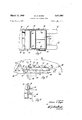
- FIGURE 5 is an enlarged fragmentary view showing in detail the guide means incorporated with the front end of the ejector floor section, and
- FIGURE 6 is an enlarged sectional view taken on line 66 of FIGURE 5.
- FIGURE 1 shows a scraper unit comprising a 4-wheel tractor 10 having front steerable wheels 12 and an engine 14 that is drivingly connected to the rear wheels 16 in a conventional manner.
- a hitch arrange ment 18 Adjacent the rear of the tractor 10, a hitch arrange ment 18 is provided for supporting the forward end of a trailing scraper bowl 20 which is supported at its rear by wheels 22.
- the hitch arrangement 18 provides a vertical axis about which the tractor and scraper bowl are connected for articulated movement and includes hydraulic means 24 for raising and lowering the forward end of the scraper bowl 20 so as to control the depth of cut and also provide an elevated position so as to permit transportation of the cut material from one location to another.
- the hydraulic means 24 acts on a coupling member 26 that extends rearwardly for rigid connection with the main bowl frame 28 which includes transversely spaced and longitudinally extending structural members 30 which carry bowl side walls 32 while other structural reenforcing members 34 span the longitudinal members and form a rigid frame unit.
- an apron 36 is provided for pivotal movement between a lowered and raised position about a transverse horizontal axis passing through a pivotal connection 38.
- a crankarm 40 has one end thereof rigidly attached to the apron at the pivotal connection 38 while the other end is pivotally connected to a double-acting hydraulic cylinder 42 supported by the main bowl frame 28 through a pivot connection 44.
- the apron 36 is moved to the raised position and the usual bowl mouth is exposed, the lower end of which is defined by a conventional transversely extending cutting blade 46.
- the rear portion of the bowl frame supports a twopiece ejector made in accordance with the invention and which can be generally described as a pull-back type.
- the ejector comprises a rear section 50 and a front section 52 which serves as the floor portion of the scraper bowl.
- the rear section 50 consists of a back wall 54 which is arcuate in cross section and extends transversely between the side walls 32 of the main bowl frame.
- the opposite sides of the back wall 54 are rigidly connected with parallel and transversely spaced arms or material retaining walls 56 and 58.
- the respective walls 56 and 58 are triangular in configuration with the apex thereof pivotally mounted to the bowl frame through aligned pivotal connections 60 and 62 so that the section 50 can rotate as a unit about a transverse horizontal axis passing through the latter-mentioned pivotal connections.
- the lower forward end of the back wall 54 is connected by a piano type hinge 64 to the section 52 which extends forwardly and terminates adjacent the cutting blade 46 with a material spreading blade 66.
- each side of the forward end of the floor section 52 is supported by guide means generally indicated by the numeral 67 which comprises a roller support bracket 68 connected to the fioor section 52, a ramp 69, and a track plate 70 secured to the side wall 32 by a plurality of bolts 72.
- Each roller bracket 68 has the lower end thereof fixed to the floor section 52 while the upper end rotatably carries a roller 74 that rests upon the upper end of the ramp 69 fixed on the side wall 32 forwardly of the track plate 70.
- the track plate 70 has outwardly projecting and longitudinally extending ribs 76 formed thereon with the lower rib located next to the ramp 69 for accommodating the roller 74 as it moves rearwardly when the ejector is raised in a manner to be described hereinafter.
- a pair of double-acting hydraulic cylinders 78 and 80 are provided for actuating the ejector and are located alongside the walls 56 and 58, respectively.
- Each of the ejector cylinders has one end thereof pivotally connected to the bowl frame adjacent the rear wheel 22 while the other end is pivotally connected to the associated wall.
- the roller 74 then moves within the track plate 70 rearwardly until full expansion of the ejector cylinders is reached. It will be understood that during such action any material within the bowl will be discharged from the bottom of the scraper bowl and the spreading blade 66 provides a uniform spread depth of the discharged material. Moreover, by causing the forward end of the ejector to ride down a ramp during the initial ejection movement, the weight of the material on the downwardly inclined floor section provides a rearwardly directed force component the aids the ejector cylinders to I raise the rear section 50 of the ejector. Thereafter, as the material drops ahead of the floor section, the spreading blade 66 cuts into the discharged layer of material to further facilitate the upward movement of the rear section 50.
- the track plate 70 of the guide means 67 is adjustably supported on the bowl frame so that the spread depth can be controlled during the ejection operation.
- the track plate 70 is formed with a plurality of equally spaced and longitudinally aligned apertures that accommodate the bolts 72 for securing the plate 70 to the side walls 32 of the scraper bowl.
- Four rows of corresponding and similarly spaced apertures 82 are formed in the side walls 32 and are located along inclined axes which are parallel to the ramp 69 so that the track plate 70 can be adjustably lowered for obtaining different spread depths.
- a scraper bowl comprising a transportable bowl frame including transversely spaced longitudinally extending side walls, a cutting edge extending transversely between the lower portions of said side walls to form a bowl mouth, a pull-back ejector in said bowl frame comprising a back wall section supported for pivotal movement about a fixed horizontal axis located above the cutting edge, said back wall section including an upstanding rear wall and a pair of laterally spaced material retaining walls fixed to said rear wall continuously with said side walls, a front floor section between said side walls and having the rear thereof hingedly connected to said back wall section adjacent the lower forward edge thereof, means for guiding the forward end of said floor section for movement along said side walls, operating means connected between said bowl frame and the back wall section for raising the latter about the fixed horizontal axis whereby the floor section is drawn rearwardly to discharge the load in said bowl, said guide means comprising a ramp and a track plate, said ramp causing the forward end of said floor section to initially drop downwardly relative to the cutting edge for substantial horizontal sliding support by the track
- said means adjustably securing said track plate to the side walls comprises a plurality of equally spaced apertures provided in a portion of said track plate and the side walls of the scraper bowl for locating and securing said track plate at a desired height relative to the cutting edge.
- each side of the forward end of the floor section supports a roller and the track plate has longitudinal ribs formed thereon for accommodating the roller.
Landscapes
- Engineering & Computer Science (AREA)
- Mining & Mineral Resources (AREA)
- Mechanical Engineering (AREA)
- Civil Engineering (AREA)
- General Engineering & Computer Science (AREA)
- Structural Engineering (AREA)
- Soil Working Implements (AREA)
- Vehicle Cleaning, Maintenance, Repair, Refitting, And Outriggers (AREA)
Description
March 11, 1969 w. H. EIGER EJECTOR FOR SCRAPER BOWL Sheet Filed July 5, 1966 INVENTOR. ZZIz'ZZzb m l Eager BL. MW .1" L1 if g? March 11, 1969 w. H. EIGER 3,431,663
EJECTOR FOR SCRAPER BOWL Filed July 5, 1966 Sheet 2 of INVENTOR.
gkzl w AT TOR/VB? United States Patent 4 Claims ABSTRACT OF THE DISCLOSURE An ejector for a scraper bowl having a transportable bowl frame that includes transversely spaced and longitudinally extending side walls. The ejector has a back wall section supported for pivotal movement about a fixed horizontal axis located above the cutting edge, and a front floor section between the side walls with the rear thereof hingedly connected to the back wall section. Guide means support the forward end of the floor section for movement along the side walls whereby raising the back wall section about its fixed pivotal axis causes the floor section to be drawn rearwardly to discharge the load in the bowl.
complete ejection of the load in the bowl.
Various forms of ejectors have been utilized for discharging a load from the scraper bowl. The most common of the prior used ejector constructions can be classified as being either of the rollout or push-out variety. The rollout ejector is hinged to the rear of the scraper bowl for pivotal movement about a fixed transverse axis and suitable means are provided for pivoting the ejector forwardly and rearwardly in the bowl. The push-out ejector, on the other hand, consists of a plate that is reciprocated along the floor of the bowl from the rear thereof toward the cutting edge. Although both of these ejectors have enjoyed wide acceptance, it is becoming apparent that as the size of the bowl increases this form of ejector construction becomes difficult to use unless a corresponding increase in the size and capacity of the hydraulic system and associated components is made for operating the ejector. Although this may be one answer to the problem of handling steadily increasing loads in scrapers, thought has been given to other solutions in the interest in arriving at an ejector design that will assure more eflicient loading and unloading of the scraper. The subject invention is one of these solutions which in operating principle uses the weight of the material in the bowl to assist ejection thereby eliminating the need for large hydraulic operating jacks and/or high pressure hydraulic systems.
Accordingly, a principal object of this invention is to provide an ejector for a scraper bowl that is so designed that the weight of the material serves to aid the operating means for moving the ejector to the ejecting position.
Another object of the invention is to provide a pull-back ejector for a scraper bowl that permits the material to be discharged from the bottom of the bowl.
A further object of this invention is to provide a scraper bowl with a two-piece ejector, one part of which constitutes the floor portion and the other part the back portion and so supported that ejection of the material occurs by moving the floor portion rearwardly and simultaneously tilting it at an increasing angle with respect to the ground so that the load is dropped by gravity.
More specifically, the invention is incorporated in a scraper bowl comprising a transportable bowl frame that includes transversely spaced and longitudinally extending side walls. A cutting blade extends between the lower portions of the side walls so as to form a bowl mouth that is located forwardly of a pull-back ejector made in accordance with the invention. In the preferred form, the
ejector comprises a back wall section supported for pivotal movement about a fixed horizontal axis located above the cutting edge. In addition, the ejector has a front floor section between the side walls and has the rear thereof hingedly connected to the back wall section adjacent the lower forward edge of the latter. Guide means support the forward end of the floor section for movement along the side walls so that upon raising the back wall section about its fixed pivotal axis, the floor section is drawn rearwardly to discharge the load in the bowl.
A more complete understanding of the subject invention will be obtained from the following detailed description when taken with the drawing in which:
FIGURE 1 is an elevation view showing a tractor and scraper bowl arrangement incorporating an ejector made in accordance with the invention;
FIGURE 2 is an enlarged elevational side view of the scraper bowl shown in FIGURE 1;
FIGURE 3 is a view similar to FIGURE 2 with the ejector located in the raised position;
FIGURE 4 is a plan view of the scraper bowl taken on line 44 of FIGURE 2;
FIGURE 5 is an enlarged fragmentary view showing in detail the guide means incorporated with the front end of the ejector floor section, and
FIGURE 6 is an enlarged sectional view taken on line 66 of FIGURE 5.
Referring now to the drawings, FIGURE 1 shows a scraper unit comprising a 4-wheel tractor 10 having front steerable wheels 12 and an engine 14 that is drivingly connected to the rear wheels 16 in a conventional manner. Adjacent the rear of the tractor 10, a hitch arrange ment 18 is provided for supporting the forward end of a trailing scraper bowl 20 which is supported at its rear by wheels 22. The hitch arrangement 18 provides a vertical axis about which the tractor and scraper bowl are connected for articulated movement and includes hydraulic means 24 for raising and lowering the forward end of the scraper bowl 20 so as to control the depth of cut and also provide an elevated position so as to permit transportation of the cut material from one location to another. The hydraulic means 24 acts on a coupling member 26 that extends rearwardly for rigid connection with the main bowl frame 28 which includes transversely spaced and longitudinally extending structural members 30 which carry bowl side walls 32 while other structural reenforcing members 34 span the longitudinal members and form a rigid frame unit.
As is conventional in scraper bowls and as best seen in FIGURE 2, an apron 36 is provided for pivotal movement between a lowered and raised position about a transverse horizontal axis passing through a pivotal connection 38. A crankarm 40 has one end thereof rigidly attached to the apron at the pivotal connection 38 while the other end is pivotally connected to a double-acting hydraulic cylinder 42 supported by the main bowl frame 28 through a pivot connection 44. Thus upon contraction of cylinder 42, the apron 36 is moved to the raised position and the usual bowl mouth is exposed, the lower end of which is defined by a conventional transversely extending cutting blade 46.
The rear portion of the bowl frame supports a twopiece ejector made in accordance with the invention and which can be generally described as a pull-back type. The ejector comprises a rear section 50 and a front section 52 which serves as the floor portion of the scraper bowl. As seen in FIGURES 2 and 4, the rear section 50 consists of a back wall 54 which is arcuate in cross section and extends transversely between the side walls 32 of the main bowl frame. The opposite sides of the back wall 54 are rigidly connected with parallel and transversely spaced arms or material retaining walls 56 and 58. The respective walls 56 and 58 are triangular in configuration with the apex thereof pivotally mounted to the bowl frame through aligned pivotal connections 60 and 62 so that the section 50 can rotate as a unit about a transverse horizontal axis passing through the latter-mentioned pivotal connections. The lower forward end of the back wall 54 is connected by a piano type hinge 64 to the section 52 which extends forwardly and terminates adjacent the cutting blade 46 with a material spreading blade 66.
As best seen in FIGURES 4 and 5, each side of the forward end of the floor section 52 is supported by guide means generally indicated by the numeral 67 which comprises a roller support bracket 68 connected to the fioor section 52, a ramp 69, and a track plate 70 secured to the side wall 32 by a plurality of bolts 72. Each roller bracket 68 has the lower end thereof fixed to the floor section 52 while the upper end rotatably carries a roller 74 that rests upon the upper end of the ramp 69 fixed on the side wall 32 forwardly of the track plate 70. It will be noted that the track plate 70 has outwardly projecting and longitudinally extending ribs 76 formed thereon with the lower rib located next to the ramp 69 for accommodating the roller 74 as it moves rearwardly when the ejector is raised in a manner to be described hereinafter.
A pair of double-acting hydraulic cylinders 78 and 80 are provided for actuating the ejector and are located alongside the walls 56 and 58, respectively. Each of the ejector cylinders has one end thereof pivotally connected to the bowl frame adjacent the rear wheel 22 while the other end is pivotally connected to the associated wall. Thus, it should be apparent that upon expanding the ejector cylinders 78 and 80, as shown in FIGURE 3, the back wall section 50 is rotated counterclockwise about the pivotal connections 60 and 62 so as to draw hinged section 52 rearwardly and cause the roller 74 to move down the ramp 69 until it engages the lower rib 76 on the track plate 70. As seen in FIGURE 5, the roller 74 then moves within the track plate 70 rearwardly until full expansion of the ejector cylinders is reached. It will be understood that during such action any material within the bowl will be discharged from the bottom of the scraper bowl and the spreading blade 66 provides a uniform spread depth of the discharged material. Moreover, by causing the forward end of the ejector to ride down a ramp during the initial ejection movement, the weight of the material on the downwardly inclined floor section provides a rearwardly directed force component the aids the ejector cylinders to I raise the rear section 50 of the ejector. Thereafter, as the material drops ahead of the floor section, the spreading blade 66 cuts into the discharged layer of material to further facilitate the upward movement of the rear section 50.
Finally, it will be noted that the track plate 70 of the guide means 67, as shown in FIGURE 5, is adjustably supported on the bowl frame so that the spread depth can be controlled during the ejection operation. In this regard, the track plate 70 is formed with a plurality of equally spaced and longitudinally aligned apertures that accommodate the bolts 72 for securing the plate 70 to the side walls 32 of the scraper bowl. Four rows of corresponding and similarly spaced apertures 82 are formed in the side walls 32 and are located along inclined axes which are parallel to the ramp 69 so that the track plate 70 can be adjustably lowered for obtaining different spread depths.
Various changes and modifications can be made in this construction without departing from the spirit of the invention. Such changes and modifications are contemplated by the inventor and he does not wish to be limited except by the scope of the appended claims.
I claim:
1. A scraper bowl comprising a transportable bowl frame including transversely spaced longitudinally extending side walls, a cutting edge extending transversely between the lower portions of said side walls to form a bowl mouth, a pull-back ejector in said bowl frame comprising a back wall section supported for pivotal movement about a fixed horizontal axis located above the cutting edge, said back wall section including an upstanding rear wall and a pair of laterally spaced material retaining walls fixed to said rear wall continuously with said side walls, a front floor section between said side walls and having the rear thereof hingedly connected to said back wall section adjacent the lower forward edge thereof, means for guiding the forward end of said floor section for movement along said side walls, operating means connected between said bowl frame and the back wall section for raising the latter about the fixed horizontal axis whereby the floor section is drawn rearwardly to discharge the load in said bowl, said guide means comprising a ramp and a track plate, said ramp causing the forward end of said floor section to initially drop downwardly relative to the cutting edge for substantial horizontal sliding support by the track plate upon energization of the operating means, and means for adjustably securing said track plate to the side walls to vary the vertical displacement of the forward end of said floor section relative to the cutting edge whereby the spread depth of the discharged material is controlled.
2. The scraper bowl of claim 1 wherein said means adjustably securing said track plate to the side walls comprises a plurality of equally spaced apertures provided in a portion of said track plate and the side walls of the scraper bowl for locating and securing said track plate at a desired height relative to the cutting edge.
3. The scraper bowl of claim 1 wherein each side of the forward end of the floor section supports a roller and the track plate has longitudinal ribs formed thereon for accommodating the roller.
4. The scraper bowl of claim 3 wherein the axis of roller rotation is located above the hinged connection between the floor section and the back wall section when the ejector is in the normal position.
References Cited UNITED STATES PATENTS 2,064,023 12/1936 Maloon 37-126 2,220,472 11/1940 Brodersen 37126 2,274,904 3/1942 Lawler 37144 2,347,291 4/ 1944 Shaetfer 37126 2,368,196 1/1945 Brodersen 37-126 3,057,090 10/1962 Mazzarins 37-426 3,274,711 9/1966 Johnson et al 37129 3,300,882 1/1967 Fryer 37-129 3,303,587 2/196'7 Rockwell 37129 XR 3,328,903 7/1967 Campbell et al. 37129 EDGAR S. BURR, Primary Examiner.
US. Cl. X.R.
Applications Claiming Priority (1)
| Application Number | Priority Date | Filing Date | Title |
|---|---|---|---|
| US56258366A | 1966-07-05 | 1966-07-05 |
Publications (1)
| Publication Number | Publication Date |
|---|---|
| US3431663A true US3431663A (en) | 1969-03-11 |
Family
ID=24246867
Family Applications (1)
| Application Number | Title | Priority Date | Filing Date |
|---|---|---|---|
| US562583A Expired - Lifetime US3431663A (en) | 1966-07-05 | 1966-07-05 | Ejector for scraper bowl |
Country Status (2)
| Country | Link |
|---|---|
| US (1) | US3431663A (en) |
| GB (1) | GB1137794A (en) |
Cited By (9)
| Publication number | Priority date | Publication date | Assignee | Title |
|---|---|---|---|---|
| US3521388A (en) * | 1967-11-22 | 1970-07-21 | Mrs Manufacturing Co | Method and apparatus for removing earth and the like materials |
| US3680234A (en) * | 1970-03-02 | 1972-08-01 | Mrs Manufacturing Co | Earth moving vehicle dumping structure |
| US3693273A (en) * | 1970-12-14 | 1972-09-26 | Caterpillar Tractor Co | Scraper apron for improved closing in rock |
| US3732636A (en) * | 1971-10-04 | 1973-05-15 | Clark Equipment Co | Unitized body structure for earth moving apparatus |
| US4071965A (en) * | 1975-04-28 | 1978-02-07 | Caterpillar Tractor Co. | Pivoted ejector with hinged door for earthmoving scrapers |
| US6032389A (en) * | 1998-05-13 | 2000-03-07 | Eagle-Picher Industries, Inc. | Earth mover with leveling device or fixed cutting edge earth mover |
| US6041528A (en) * | 1998-09-23 | 2000-03-28 | Harvey Mfg. Corp. | High performance ejector scraper |
| US6092316A (en) * | 1997-01-27 | 2000-07-25 | Kan-Am Industries, Inc. | Ejector apparatus for an earth moving scraper bowl |
| US20070267225A1 (en) * | 2006-05-19 | 2007-11-22 | Congdon Thomas M | Auger loading apparatus and machine with same |
Citations (10)
| Publication number | Priority date | Publication date | Assignee | Title |
|---|---|---|---|---|
| US2064023A (en) * | 1936-02-08 | 1936-12-15 | Heil Co | Scraper |
| US2220472A (en) * | 1939-02-11 | 1940-11-05 | Slusser Mclean Scraper Company | Heavy duty scraper |
| US2274904A (en) * | 1939-08-14 | 1942-03-03 | Buckeye Traction Ditcher Co | Trail builder attachment for tractors |
| US2347291A (en) * | 1942-10-28 | 1944-04-25 | Gar Wood Ind Inc | Scraper |
| US2368196A (en) * | 1941-02-11 | 1945-01-30 | Slusser Mclean Scraper Company | Hauling scraper |
| US3057090A (en) * | 1959-09-21 | 1962-10-09 | Gen Motors Corp | Scraper bowl |
| US3274711A (en) * | 1963-05-13 | 1966-09-27 | Johnson Mfg Company | Earth scraper with retractable bottom wall |
| US3300882A (en) * | 1963-12-23 | 1967-01-31 | Gen Motors Corp | Ejector for scrapers |
| US3303587A (en) * | 1964-03-06 | 1967-02-14 | Allis Chalmers Mfg Co | Earthmover |
| US3328903A (en) * | 1964-04-02 | 1967-07-04 | Caterpillar Tractor Co | Ejector mechanism for earthmoving scraper |
-
1966
- 1966-07-05 US US562583A patent/US3431663A/en not_active Expired - Lifetime
-
1967
- 1967-06-29 GB GB30082/67A patent/GB1137794A/en not_active Expired
Patent Citations (10)
| Publication number | Priority date | Publication date | Assignee | Title |
|---|---|---|---|---|
| US2064023A (en) * | 1936-02-08 | 1936-12-15 | Heil Co | Scraper |
| US2220472A (en) * | 1939-02-11 | 1940-11-05 | Slusser Mclean Scraper Company | Heavy duty scraper |
| US2274904A (en) * | 1939-08-14 | 1942-03-03 | Buckeye Traction Ditcher Co | Trail builder attachment for tractors |
| US2368196A (en) * | 1941-02-11 | 1945-01-30 | Slusser Mclean Scraper Company | Hauling scraper |
| US2347291A (en) * | 1942-10-28 | 1944-04-25 | Gar Wood Ind Inc | Scraper |
| US3057090A (en) * | 1959-09-21 | 1962-10-09 | Gen Motors Corp | Scraper bowl |
| US3274711A (en) * | 1963-05-13 | 1966-09-27 | Johnson Mfg Company | Earth scraper with retractable bottom wall |
| US3300882A (en) * | 1963-12-23 | 1967-01-31 | Gen Motors Corp | Ejector for scrapers |
| US3303587A (en) * | 1964-03-06 | 1967-02-14 | Allis Chalmers Mfg Co | Earthmover |
| US3328903A (en) * | 1964-04-02 | 1967-07-04 | Caterpillar Tractor Co | Ejector mechanism for earthmoving scraper |
Cited By (10)
| Publication number | Priority date | Publication date | Assignee | Title |
|---|---|---|---|---|
| US3521388A (en) * | 1967-11-22 | 1970-07-21 | Mrs Manufacturing Co | Method and apparatus for removing earth and the like materials |
| US3680234A (en) * | 1970-03-02 | 1972-08-01 | Mrs Manufacturing Co | Earth moving vehicle dumping structure |
| US3693273A (en) * | 1970-12-14 | 1972-09-26 | Caterpillar Tractor Co | Scraper apron for improved closing in rock |
| US3732636A (en) * | 1971-10-04 | 1973-05-15 | Clark Equipment Co | Unitized body structure for earth moving apparatus |
| US4071965A (en) * | 1975-04-28 | 1978-02-07 | Caterpillar Tractor Co. | Pivoted ejector with hinged door for earthmoving scrapers |
| US6092316A (en) * | 1997-01-27 | 2000-07-25 | Kan-Am Industries, Inc. | Ejector apparatus for an earth moving scraper bowl |
| US6032389A (en) * | 1998-05-13 | 2000-03-07 | Eagle-Picher Industries, Inc. | Earth mover with leveling device or fixed cutting edge earth mover |
| US6041528A (en) * | 1998-09-23 | 2000-03-28 | Harvey Mfg. Corp. | High performance ejector scraper |
| US20070267225A1 (en) * | 2006-05-19 | 2007-11-22 | Congdon Thomas M | Auger loading apparatus and machine with same |
| US7707754B2 (en) * | 2006-05-19 | 2010-05-04 | Caterpillar Inc. | Auger loading apparatus and machine with same |
Also Published As
| Publication number | Publication date |
|---|---|
| GB1137794A (en) | 1968-12-27 |
Similar Documents
| Publication | Publication Date | Title |
|---|---|---|
| US3210868A (en) | Earthmoving scraper with auxiliary bowl mounted conveyor | |
| US9605407B2 (en) | Apparatus with divergent V-wing blade configuration | |
| US3431663A (en) | Ejector for scraper bowl | |
| US2988832A (en) | Positive ejection mechanism for earth moving apparatus | |
| US2994976A (en) | Stabilizer for positive ejection mechanism for earth moving apparatus | |
| US6019568A (en) | Spill gate for trailer tipper | |
| US5839212A (en) | Ejector apparatus for an earth moving scraper bowl | |
| US2252763A (en) | Scraper | |
| DE1484707B2 (en) | Schurfkubel vehicle | |
| US4308677A (en) | Ejector type scraper | |
| US3176863A (en) | Ejector bucket for front end loader | |
| US2271790A (en) | Load ejector | |
| US2078501A (en) | Road scraper | |
| US4366635A (en) | Pivoting ejector for elevator scraper | |
| US2304786A (en) | Scraper | |
| US3782573A (en) | Bucket for use on a loader, tractor or the like | |
| US5181574A (en) | Scraper blade mount for bulldozer | |
| US2169946A (en) | Scraper | |
| US4055007A (en) | Earth handling apparatus | |
| US3483640A (en) | Apparatus for improving the stability of an elevator scraper during unloading | |
| US2112105A (en) | Telescoping scraper | |
| US3057090A (en) | Scraper bowl | |
| US2513129A (en) | Land leveling drag | |
| CA1051832A (en) | Scraper bowl with movable floor section | |
| JPS586813B2 (en) | Dokousukre Pasiyariyou |