US3412444A - Method for making capacitor having porous electrode of sintered powder on foil - Google Patents
Method for making capacitor having porous electrode of sintered powder on foil Download PDFInfo
- Publication number
- US3412444A US3412444A US546714A US54671466A US3412444A US 3412444 A US3412444 A US 3412444A US 546714 A US546714 A US 546714A US 54671466 A US54671466 A US 54671466A US 3412444 A US3412444 A US 3412444A
- Authority
- US
- United States
- Prior art keywords
- foil
- powder
- tantalum
- strip
- capacitors
- Prior art date
- Legal status (The legal status is an assumption and is not a legal conclusion. Google has not performed a legal analysis and makes no representation as to the accuracy of the status listed.)
- Expired - Lifetime
Links
- 239000003990 capacitor Substances 0.000 title description 73
- 239000011888 foil Substances 0.000 title description 67
- 239000000843 powder Substances 0.000 title description 62
- 238000000034 method Methods 0.000 title description 56
- GUVRBAGPIYLISA-UHFFFAOYSA-N tantalum atom Chemical compound [Ta] GUVRBAGPIYLISA-UHFFFAOYSA-N 0.000 description 61
- 229910052751 metal Inorganic materials 0.000 description 39
- 239000002184 metal Substances 0.000 description 39
- 239000008188 pellet Substances 0.000 description 29
- 238000000576 coating method Methods 0.000 description 28
- 230000008569 process Effects 0.000 description 25
- 239000011248 coating agent Substances 0.000 description 24
- 238000005245 sintering Methods 0.000 description 24
- 239000000463 material Substances 0.000 description 23
- 239000007787 solid Substances 0.000 description 21
- 229910052715 tantalum Inorganic materials 0.000 description 21
- NUJOXMJBOLGQSY-UHFFFAOYSA-N manganese dioxide Chemical compound O=[Mn]=O NUJOXMJBOLGQSY-UHFFFAOYSA-N 0.000 description 16
- 230000000873 masking effect Effects 0.000 description 12
- 239000004065 semiconductor Substances 0.000 description 11
- 238000004519 manufacturing process Methods 0.000 description 10
- 239000012298 atmosphere Substances 0.000 description 9
- 239000007788 liquid Substances 0.000 description 9
- 238000001816 cooling Methods 0.000 description 7
- 238000012545 processing Methods 0.000 description 7
- XKRFYHLGVUSROY-UHFFFAOYSA-N Argon Chemical compound [Ar] XKRFYHLGVUSROY-UHFFFAOYSA-N 0.000 description 6
- UHOVQNZJYSORNB-UHFFFAOYSA-N Benzene Chemical compound C1=CC=CC=C1 UHOVQNZJYSORNB-UHFFFAOYSA-N 0.000 description 6
- KFZMGEQAYNKOFK-UHFFFAOYSA-N Isopropanol Chemical compound CC(C)O KFZMGEQAYNKOFK-UHFFFAOYSA-N 0.000 description 6
- BQCADISMDOOEFD-UHFFFAOYSA-N Silver Chemical compound [Ag] BQCADISMDOOEFD-UHFFFAOYSA-N 0.000 description 6
- YXFVVABEGXRONW-UHFFFAOYSA-N Toluene Chemical compound CC1=CC=CC=C1 YXFVVABEGXRONW-UHFFFAOYSA-N 0.000 description 6
- 238000005520 cutting process Methods 0.000 description 6
- 229910052709 silver Inorganic materials 0.000 description 6
- 239000004332 silver Substances 0.000 description 6
- 238000010924 continuous production Methods 0.000 description 5
- MIVBAHRSNUNMPP-UHFFFAOYSA-N manganese(2+);dinitrate Chemical compound [Mn+2].[O-][N+]([O-])=O.[O-][N+]([O-])=O MIVBAHRSNUNMPP-UHFFFAOYSA-N 0.000 description 5
- XLYOFNOQVPJJNP-UHFFFAOYSA-N water Chemical compound O XLYOFNOQVPJJNP-UHFFFAOYSA-N 0.000 description 5
- LYCAIKOWRPUZTN-UHFFFAOYSA-N Ethylene glycol Chemical compound OCCO LYCAIKOWRPUZTN-UHFFFAOYSA-N 0.000 description 4
- NBIIXXVUZAFLBC-UHFFFAOYSA-N Phosphoric acid Chemical compound OP(O)(O)=O NBIIXXVUZAFLBC-UHFFFAOYSA-N 0.000 description 4
- 239000011230 binding agent Substances 0.000 description 4
- 238000010438 heat treatment Methods 0.000 description 4
- 239000011261 inert gas Substances 0.000 description 4
- WABPQHHGFIMREM-UHFFFAOYSA-N lead(0) Chemical compound [Pb] WABPQHHGFIMREM-UHFFFAOYSA-N 0.000 description 4
- 238000011068 loading method Methods 0.000 description 4
- 238000003825 pressing Methods 0.000 description 4
- 238000000926 separation method Methods 0.000 description 4
- OKTJSMMVPCPJKN-UHFFFAOYSA-N Carbon Chemical compound [C] OKTJSMMVPCPJKN-UHFFFAOYSA-N 0.000 description 3
- 241000237858 Gastropoda Species 0.000 description 3
- 238000007743 anodising Methods 0.000 description 3
- 229910052786 argon Inorganic materials 0.000 description 3
- 238000000151 deposition Methods 0.000 description 3
- 238000010586 diagram Methods 0.000 description 3
- 238000001035 drying Methods 0.000 description 3
- 239000003792 electrolyte Substances 0.000 description 3
- 229910002804 graphite Inorganic materials 0.000 description 3
- 239000010439 graphite Substances 0.000 description 3
- 239000000243 solution Substances 0.000 description 3
- 238000010561 standard procedure Methods 0.000 description 3
- RTAQQCXQSZGOHL-UHFFFAOYSA-N Titanium Chemical compound [Ti] RTAQQCXQSZGOHL-UHFFFAOYSA-N 0.000 description 2
- QCWXUUIWCKQGHC-UHFFFAOYSA-N Zirconium Chemical compound [Zr] QCWXUUIWCKQGHC-UHFFFAOYSA-N 0.000 description 2
- 229910052782 aluminium Inorganic materials 0.000 description 2
- XAGFODPZIPBFFR-UHFFFAOYSA-N aluminium Chemical compound [Al] XAGFODPZIPBFFR-UHFFFAOYSA-N 0.000 description 2
- 229910000147 aluminium phosphate Inorganic materials 0.000 description 2
- 238000013459 approach Methods 0.000 description 2
- 238000004140 cleaning Methods 0.000 description 2
- 239000004020 conductor Substances 0.000 description 2
- 238000007598 dipping method Methods 0.000 description 2
- 239000012153 distilled water Substances 0.000 description 2
- AMWRITDGCCNYAT-UHFFFAOYSA-L hydroxy(oxo)manganese;manganese Chemical compound [Mn].O[Mn]=O.O[Mn]=O AMWRITDGCCNYAT-UHFFFAOYSA-L 0.000 description 2
- WGCNASOHLSPBMP-UHFFFAOYSA-N hydroxyacetaldehyde Natural products OCC=O WGCNASOHLSPBMP-UHFFFAOYSA-N 0.000 description 2
- 229910052758 niobium Inorganic materials 0.000 description 2
- 239000010955 niobium Substances 0.000 description 2
- GUCVJGMIXFAOAE-UHFFFAOYSA-N niobium atom Chemical compound [Nb] GUCVJGMIXFAOAE-UHFFFAOYSA-N 0.000 description 2
- BPUBBGLMJRNUCC-UHFFFAOYSA-N oxygen(2-);tantalum(5+) Chemical compound [O-2].[O-2].[O-2].[O-2].[O-2].[Ta+5].[Ta+5] BPUBBGLMJRNUCC-UHFFFAOYSA-N 0.000 description 2
- 238000000197 pyrolysis Methods 0.000 description 2
- 239000002002 slurry Substances 0.000 description 2
- 229910001936 tantalum oxide Inorganic materials 0.000 description 2
- 239000010936 titanium Substances 0.000 description 2
- 229910052719 titanium Inorganic materials 0.000 description 2
- 229910052726 zirconium Inorganic materials 0.000 description 2
- 241000499489 Castor canadensis Species 0.000 description 1
- 235000011779 Menyanthes trifoliata Nutrition 0.000 description 1
- XSTXAVWGXDQKEL-UHFFFAOYSA-N Trichloroethylene Chemical group ClC=C(Cl)Cl XSTXAVWGXDQKEL-UHFFFAOYSA-N 0.000 description 1
- 239000007864 aqueous solution Substances 0.000 description 1
- 239000012300 argon atmosphere Substances 0.000 description 1
- 239000010953 base metal Substances 0.000 description 1
- 230000015572 biosynthetic process Effects 0.000 description 1
- 230000000740 bleeding effect Effects 0.000 description 1
- 239000010406 cathode material Substances 0.000 description 1
- 238000011109 contamination Methods 0.000 description 1
- 238000012937 correction Methods 0.000 description 1
- 230000007423 decrease Effects 0.000 description 1
- 230000001419 dependent effect Effects 0.000 description 1
- 230000000994 depressogenic effect Effects 0.000 description 1
- 230000000694 effects Effects 0.000 description 1
- 229920001971 elastomer Polymers 0.000 description 1
- 230000008030 elimination Effects 0.000 description 1
- 238000003379 elimination reaction Methods 0.000 description 1
- 238000005530 etching Methods 0.000 description 1
- 230000008570 general process Effects 0.000 description 1
- 239000012535 impurity Substances 0.000 description 1
- 238000011065 in-situ storage Methods 0.000 description 1
- 238000007373 indentation Methods 0.000 description 1
- 230000006698 induction Effects 0.000 description 1
- 239000011572 manganese Substances 0.000 description 1
- 235000012054 meals Nutrition 0.000 description 1
- 238000002156 mixing Methods 0.000 description 1
- 239000002991 molded plastic Substances 0.000 description 1
- 230000003647 oxidation Effects 0.000 description 1
- 238000007254 oxidation reaction Methods 0.000 description 1
- 238000004806 packaging method and process Methods 0.000 description 1
- 239000003973 paint Substances 0.000 description 1
- 239000000088 plastic resin Substances 0.000 description 1
- 239000010453 quartz Substances 0.000 description 1
- 238000007493 shaping process Methods 0.000 description 1
- VYPSYNLAJGMNEJ-UHFFFAOYSA-N silicon dioxide Inorganic materials O=[Si]=O VYPSYNLAJGMNEJ-UHFFFAOYSA-N 0.000 description 1
- 229920002379 silicone rubber Polymers 0.000 description 1
- 238000005476 soldering Methods 0.000 description 1
- 239000000126 substance Substances 0.000 description 1
- 239000002966 varnish Substances 0.000 description 1
- 238000003466 welding Methods 0.000 description 1
Images


Classifications
-
- H—ELECTRICITY
- H01—ELECTRIC ELEMENTS
- H01G—CAPACITORS; CAPACITORS, RECTIFIERS, DETECTORS, SWITCHING DEVICES, LIGHT-SENSITIVE OR TEMPERATURE-SENSITIVE DEVICES OF THE ELECTROLYTIC TYPE
- H01G9/00—Electrolytic capacitors, rectifiers, detectors, switching devices, light-sensitive or temperature-sensitive devices; Processes of their manufacture
- H01G9/0029—Processes of manufacture
-
- Y—GENERAL TAGGING OF NEW TECHNOLOGICAL DEVELOPMENTS; GENERAL TAGGING OF CROSS-SECTIONAL TECHNOLOGIES SPANNING OVER SEVERAL SECTIONS OF THE IPC; TECHNICAL SUBJECTS COVERED BY FORMER USPC CROSS-REFERENCE ART COLLECTIONS [XRACs] AND DIGESTS
- Y10—TECHNICAL SUBJECTS COVERED BY FORMER USPC
- Y10T—TECHNICAL SUBJECTS COVERED BY FORMER US CLASSIFICATION
- Y10T29/00—Metal working
- Y10T29/43—Electric condenser making
Definitions
- ABSTRACT on THE DISCLOSURE A method for fabricating structures suitable for use as anodes for capacitors. Moistened powder is deposited on each of film-forming metal appendages which extend from and are integral with a film-forming metal strip. The powder is fused to the appendages at a temperature below the sintering temperature of the film-forming metal thereby providing a porous mass of the powder bonded to each of the appendages. The porous mass and the appendages are thereafter sintered to provide capacitor anodes.
- the present invention relates to electrolytic capacitors and more particularly relates to novel solid electrolytic capacitors.
- solid electrolytic capacitors may be manufactured by the following method: A sintered porous slug of a valve metal such as tantalum, zirconium, aluminum, niobium, and titanium is anodized in an electrolyte to form an oxide layer on the surfaces of the slug.
- the oxide layer serves as a dielectric for the capacitor.
- a semiconductor coating is applied over the oxide layer and an electrically conducting material, such as graphite and silver paint, is applied to the semiconductor layer.
- the semiconductor coating and electrically conducting coating serves as a cathode and the original metallic slu serves as an anode. After connecting leads to the base metal (anode) and to the conducting coating (cathode), the solid electrolytic capacitor is sealed in a metal case or is molded with a plastic resin.
- the basic slug is a porous tantalum slug obtained by pressing and sintering tantalum powder.
- the tantalum slug is then anodized in an electrolyte such as phosphoric acid to form an oxide (dielectric) layer on the surfaces thereof.
- a film of semiconductor material, such as manganese dioxide is closely attached to the oxide layer by dipping the anodized slugs in an aqueous solution of manganese nitrate and converting the manganese nitrate to manganese dioxide by pyrolysis.
- the manganese dioxide layer is then coated with a conducting layer such as graphite and silver.
- solid electrolytic capacitors can be formed by depositing a metallic powder on a foil of the same material and sintering the powder to form a solid pellet bonded to the foil. The foil and pellet are then anodized to form a dielectric layer and a semiconductor coating and conducting coating are added as previously described to form a cathode. The foil and the pellet serve as an anode for the capacitor.
- the powder on foil approach to capacitor manufacturing was conceived to eliminate handling problems for small solid electrolytic capacitors.
- the handling of powder on foil capacitors is significantly reduced as compared to the handling involved in the use of sintered slugs. It has also been found that elimination of the pressing operation and the binder previously associated with sintering significantly improves the quality of solid electrolytic capacitors. These capacitors can be operated safely and reliably at a higher percentage of the formation voltage of the oxide film than capacitors made according to the aforementioned sintered slug procedures.
- Powder on foil capacitors have previously been made by dispensing metallic powder droplets in a carrier liquid onto a film-forming metal provided with depressions or indentations for containing the metallic powder.
- the metallic powder and film-forming metal must be of the same material.
- the foil containing a plurality of individual powder droplets is processed as a whole and the completed individual capacitors are separated from the foil at the end of the major processing steps. This procedure reduces the amount of handling of individual capacitors and eliminates contamination and damage during processing by eliminating the pressing of individual slugs and the use of binders. This procedure is advantageous in that it lends itself to mechanization.
- problems involved in the fabrication of powder on foil capacitors as previously described. These problems will be discussed in the following paragraphs.
- the foil containing the metallic powder droplets has to be sintered in a horizontal position because, after drying, the powder without binder will fall off the foil in any other position.
- the wet powder cannot be introduced to the sintering furnace because the liquid will turn to steam at sintering temperatures to explode the pellets.
- This limitation also makes handling delicate, especially after the powder has been dried. Also, it limits the loading density of the vacuum sintering furnaces which are usually used.
- the present invention has eliminated the above mentioned problems by the addition of a process step and by the use of preformed continuous strips of foil to facilitate separation of individual capacitors and loading in the sintering furnace.
- the additional step which will be more fully described in this specification, involves passing the foil through a continuous furnace containing an inert atmosphere after the powder has been deposited in the depressions. The powder is fused and/or bonded. to the foil in the continuous furnace. After this step, the foil can be handled freely. For example, a strip of fused and bonded pellets can be wound on a frame and sintered in any position.
- Capacitors produced by the method of the present invention are readily distinguishable over prior art powder on foil capacitors because the semiconductor coating and conductive coating completely encloses the sintered pellet and the backing foil portion containing the pellet.
- the semiconductor coatings and conductive coatings are added to the top of the pellet contained in a depression in the foil. Thus, extra capacitance is obtained by covering the dielectric oxide layer on the back and sides of the capacitor.
- the present invention in another of its aspects, relates to novel features of the instrumentalities described herein for teaching the principal object of the invention and to the novel principles employed in the instrumentalities whether or not these features and principles may be used in the said object and/ or in the said field.
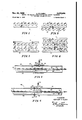
- FIGURE 1 shows a single row of foil cups integrally attached to a strip of foil.
- FIGURE 2 shows a row of foil cups on each side of a strip of foil.
- FIGURE 3 shows two rows of foil cups integrally formed with two strips of foil.
- FIGURE 4 shows an array of several rows of foil cups with interconnections required for dimensional stability during processing.
- FIGURE 5 is an illustrative embodiment of one type of continuous type furnace which can be used to fuse the powder to the foil.
- FIGURE 6 is an illustrative embodiment of another type of continuous type furnace which can be used to fuse the powder to the foil.
- FIGURE 7 is .a view illustrating how a strip of foil cups may be wound around a frame so as to facilitate loading in a batch-type sintering furnace.
- FIGURE 8 is a perspective view of a means for applying masking material to the strip of foil cups.
- FIGURE 9 is a fiow diagram for continuously processing powder on foil capacitors.
- the present invention is a group of unitarily fabricated capacitors.
- the capacitors are fabricated from a strip of film forming metal having multiple appendages extending therefrom and integrally joined thereto and a mass of said metal fusibly held on the appendages.
- the appendages are holding members for the masses" of said metal.
- a dielectric oxide coating, semiconductor coating, and conductive coating are deposited over the appendages and masses of metal to form solid electrolytic capacitors.
- the mass of said metal may be a porous sintered mass obtained by dispensing a controlled deposit of metallic powder in a depression formed in the appendage and by fusing the powder to the depression. After the metallic powder is fused to the appendage it is sintered using standard techniques.
- FIGURE 1 illustrates a strip of metal 10 with a row of cups 11 integrally formed thereon.
- FIGURE 2 illustrates a strip of meal 12 with a row of cups 13 integrally formed on each side thereof.
- FIGURE 3 illustrates a pair of integrally formed strips 14 and 15 having a plurality of cups 16 formed therebetween.
- FIGURE 4 illustrates several rows of integrally formed strips 17 and cups 18.
- Common to all of the approaches shown in FIGURES 1 through 4 is the connection of individual integrally formed foil cups to a strip of metal.
- FIGURES 1 through 4 It can be seen in FIGURES 1 through 4 that the cups are so attached to the strips that cutting along straight lines will separate individual rows to strips and will separate individual capacitors. It can also be seen that individual capacitors can be separated by cutting the reduced portion connecting the cups or depressed portions to the strips. Cutting the reduced portion connecting the cups to the strips is considerably easier than cutting around the entire cup as previously described.
- tantalum powder is being deposited onto tantalum foil.
- the balance of the disclosed capacitor fabrication processes will also be directed towards the fabrication of solid electrolytic tantalum capacitors.
- Tantalum powder is dried and fused onto tantalum foil by passing strips of the foil through a continuous furnace such as the tube type furnaces shown in FIG- URES 5 and 6. An inert atmosphere is obtained in the continuous furnaces by bleeding argon or a similar material therein.
- the temperatures required for the fusing operation vary between 1400 C. and the final sintering temperature of 2000 C. upwards. These high temperatures require the use of materials that will not contaminate the tantalum foil and powder. Suitable methods of heat shielding, cooling, supporting the foil, etc. have to be employed to prevent undesirable side effects. Generally, all components held at high temperatures should be made of tantalum.
- the time required for fusing will vary, obviously, according to the temperature employed. Several minutes will be required at lower temperatures while seconds will be sufiicient at higher temperatures. It is to be pointed out that this is a pre-sintering process. The purpose of this portion of the process is to secure the tantalum powder to the tantalum foil so that handling is facilitated. A method for continuously sintering tantalum capacitors in an inert atmosphere as contrasted to a vacuum atmosphere will be discussed later in this specification.
- FIGURE 5 An RF induction heated tube furnace 23 for continuously fusing tantalum powder to tantalum foil can be discussed.
- a fragmentary view of the walls 24 of the furnace 23 is shown in FIGURE 5.
- RF heater coils 25 are disposed about the walls 24 and are connected to an appropriate power source.
- Platens 26 and 27 are disposed within the tube walls 24 so as to be in field of the coils 25.
- the platens 26 and 27 are of high resistivity metal and develop heat because of eddy current losses therein.
- the port 33 is disposed just above the platens 26 and 27 so as to permit the inert gas arriving in the the direction of the arrow 34 to be distributed in the direction of the arrows 35' and 36.
- the strip 30 moves in the direction of the arrow 37.
- the cooling plate 29 is a means for quickly cooling the fused powder droplets 32 before the droplet is subjected to atmospheric conditions.
- FIGURE 6 a resistance heated continuous furnace for fusing and bonding tantalum powder to tantalum foil can be discussed.
- FIGURE 6 A fragmentary View of the wall 41 of the furnace 40 is shown in FIGURE 6.
- the wall 41 encloses the resistance heated platens 42 and 43 which are coupled in series and connected to an appropriate power source by the wires 44 and 45.
- feedthrough means 46 in the wall 41 for the wires 44 and 45.
- a supporting plate 47 and cooling plate 48 disposed in the furnace 40. It can be seen that the supporting plate 47 and cooling plate 48 are disposed so as to direct the strip 49 of cups 50' containing powder droplets 51 between the platens 42 and 43.
- the entrance port 52 for introducing inert gases to the furnace 40.
- the entrance port is disposed so that inert gas entering in the direction of the arrow 53 is distributed over the platens 42 and 43 in the direction of the arrows 54 and 55.
- the strip 49 moves in the direction of the arrow 56.
- the tubular wall in the furnaces 23 and 40 may be either tantalum or quartz.
- the platens 26 and 27 in the furnace 23 and the platens 42 and 43 in the furnace 40 may be tantalum or a suitable material which will not contaminate tantalum.
- FIGURE 7 a view illustrating how a strip of fused tantalum foil and tantalum powder droplets may be wound around a frame can be discussed.
- a strip of foil can be wound around a vacuum furnace frame as shown in FIGURE 7.
- the vacuum furnace frame consists of the horizontal member 59 and the U-shaped member 60 welded thereto at the weld points 61 and 62.
- a strip 63 of tantalum powder pellets 64 may be wound around the frame substantially as shown in FIGURE 7.
- the frame then can be suspended in a vacuum sintering furnace.
- the purpose of wrapping the strip 63 around the frame is to facilitate handling and to increase furnace loading.
- masking material is applied to the foil in order to limit the area to be covered with a semiconductor material, such as manganese dioxide, and subsequent cathode materials.
- a semiconductor material such as manganese dioxide
- cathode materials a means for applying a masking material, such as silicon rubber or heat resistant varnish, can be discussed.
- a base 67 which can be fabricated of any suitable structural material.
- a pair of opposing rollers 68 and 69 are rotatably mounted on the base 67.
- the roller 68 rotates in the direction of the arrow 68' and the roller 69 rotates in the direction of the arrow 69'.
- suitable rollers 68 and 69 can be made of a hard core, covered with rubber for applying the masking material to the foil.
- the rollers are slowly driven by a motor means not shown in FIGURE 8.
- feeding means 70 and 71 for applying masking material to the rollers 68 and 69 which is, in turn, applied to the strip 72 which has the pellets 73 attached thereto. It can be seen that the masking material is applied to both sides of the strip and the portion connecting each pellet 73. The strip is moved in the direction of the arrow 74 as the masking material is applied. After the masking material is applied, the strips of pellets may be dipped in various solutions for the application of a semiconductor material.
- FIGURE 9 a continuous process flow diagram for producing powder on foil capacitors can be discussed. As stated previously, for illustrative purposes, this flow chart will be directed towards fabricating solid electrolytic tantalum capacitors.
- the first step in the continuous process which is designated as 75, consists of shaping the tantalum foil for receiving the powdered tantalum.
- This step assumes, for illustrative purposes, that the powdered tantalum is deposited in a cup or depression formed in the tantalum foil. As stated previously, the powder may be deposited on flat foil.
- the cup or depression may be made by any number of thin metal forming techniques, and need not be further discussed in this specification. Tantalum foil, 0.002 inch thick having 0.2 inch diameter cups formed 0.1 inch deep is obviously easy to form. The various configurations of foil strips have been discussed in conjunction with FIGURES 1 through 4.
- the next step in the continuous process involves cleaning the preformed tantalum foil strip to remove oxides, dirt, etc. Cleaning solutions, such as trichlorethylene are adequate for this step of process. Chemical or electrochemical etching of the foil may improve the surface purity of the foil and remove impurities introduced when the foil is preshaped.
- the next step consists of dispensing tantalum powder into the depressions formed in the tantalum foil. It has been found that controlled amounts of tantalum or other metallic powders can be deposited in a carrier liquid.
- a slurry is formed by mixing tantalum powder in liquids such as distilled water, isopropyl alcohol, benzene, toluene, distilled water mixed with glycol, and the like. Liquids are selected on the basis of viscosity, surface tension and ease of removal from the powder.
- the slurry obtained is placed in a dispensing means such as the dropper shown in FIGURE 9. Control of the drop size is attained by a number of factors.
- the dense tantalum powder settles to the bottom of the dispensing means and a vibrator means, associated with the dispensing means, is used to assure free and uniform flow of tantalum powder in the capillary tube of the dispensing means.
- the dropping rate is also controlled .by the amount of liquid fed into the dispensing means, the surface te nsion of the liquid and the material of the tip of the dispensing means.
- the dispensing of tantalum powder by the means and methods described above is a simple way for measuring small amounts of powder such as 10-100 mg. amounts.
- the next step in the process consists of drying the droplet of tantalum powder. As shown in the illustrative flow diagram, drying may be accomplished by a heating means such as an infrared lamp.
- the next step in the process consists of fusing the tantalum powder to the tantalum foil.
- the fusing operation may be carried out in a continuous type furnace such as described in conjunction with FIG- URES and 6.
- the temperatures required in this step vary between 1400 C. and the final sintering temperatures of 2000 C. upwards.
- residence time in the continuous furnace will vary according to the temperatures employed. Several minutes will be required at the lower temperatures, while seconds will be sufiicient at higher temperatures. It has been found that 1500 C. for 2 minutes is sufiicient to fuse droplets approximately 0.25 inch in diameter and 0.1 inch thick.
- this step of the process fusing of tantalum powder onto tantalum foil, takes place in an inert atmosphere.
- next two steps in the process designated as 80 and 81 are illustrated at batch-type operations but may be accomplished continuously if a continuous vacuum furnace is available or if sintering is accomplished in an inert atmosphere. It has been found that by using high purity tantalum foil and high purity powder, sintering accomplished in an argon atmosphere is quite satisfactory.
- the sintering furnace can be continuous with the fusing furnace previously described or can replace the fusing furnace.
- strips of fused tantalum pellets are wound about a frame as described in conjunction with FIGURE 7 and the frame is suspended in a vacuum furnace as depicted in the step designated as 81.
- the next step in the process consists of anodizing the foil and sintered pellet to obtain a dielectric oxide layer.
- Tantalum film and sintered pellets may be suitably anodized in an electrolyte such as phosphoric acid.
- the next step, designated as 8 3 is the application of a masking material to limit the area of the semiconductor coating.
- the masking material may be rolled onto the strip as discussed in conjunction with FIGURE 8.
- the next step in the process involves curing the masking material applied in the previous step of the process. As illustrated in FIGURE 9, this step may be accomplished with a heating means such as an infrared lamp.
- the next step in the process designated as 85 involves the application of manganese nitrate (Mn (NO to the anodized pellet. This may be done by dipping as shown in FIGURE 9.
- Mn manganese nitrate
- the pellets, which are porous tantalum bodies, are impregnated with the manganese nitrate.
- the next step involves pyrolysis of the foil and pellets covered with manganese nitrate to obtain a manganese dioxide coating.
- the foils and pellets are pyrolyzed at temperatures between 200 and 400 C. following standard procedures.
- the next illustrative step in the process involves the reformation of the oxide coating in any places where it may have been damaged. As illustrated in FIGURE 9, this step, if required, may be accomplished in a typical anodic bath following standard procedures.
- the next step in the process involves the application of a conducting material over the manganese dioxide layer to form a cathode for the capacitor.
- the conductive coating applied in this step of the process may be graphite which is colloidally suspended in a solution.
- the next step in the process involves curing the conducting coating applied in the previous step.
- the curing operation requiring approximately 150 C.
- a heating means such as an infrared light.
- step 90 consists of applying another conductive coating, such as silver, over the conductive coating previously applied.
- the silver may be applied by the bath means illustrated in FIGURE 9. It can be seen that the strip moves through the silver bath so that only the pellets and portion of the backing material covered with tantalum oxide and manganese dioxide are covered with silver. The reduced portion of the strip which was previously masked is not covered.
- the next step in the process involves curing the conductive coating applied in the previous step. As shown in FIGURE 9, this curing operation requiring approximately C. may be accomplished with a heating means, such as an infrared lamp.
- the next step in the process consists of welding or otherwise connecting a lead wire to the tantalum foil to provide an anode lead for the capacitor.
- the lead wire is attached to the tantalum foil in a position removed from the tantalum oxide and manganese oxide coating so as to prevent shorting the anode of the capacitor to the cathode.
- the next step in the process consists of soldering or otherwise connecting a lead wire to the conductive coatings applied over the manganese dioxide.
- the lead wire attached in this step serves as a cathode lead for the capacitor.
- the next and final illustrated step in the process involves separating the individual capacitors from the foil strip and packaging the capacitor.
- the package may be a molded plastic container or a hermetically sealed container. As stated previously, the separation of individual capacitors is accomplished easily by cutting the reduced portion of the strip leading to the pellet.
- the resulting product obtained after the anodic oxidation step is a strip of metallic foil having a plurality of spaced apart capacitor anodes at tached thereto.
- Each capacitor anode has a backing portion of film forming metal which is an integral appendage of the strip and a porous sintered mass of said metal which is fused thereto.
- a method for fabricating anodes suitable for use in said capacitors which comprises the steps of providing a strip of a film-forming metal which has been pre-shaped to have integral appendages extending therefrom and associated each with one of the anodes,
- each mass to convert it to a porous pellet of said metal and to integrally join said porous pellet with its associated appendage so that it constitutes together with said appendage the anode for one of said capacitors.
- said moistened powder consists essentially of a metal selected from the group consisting of tantalum, aluminum, niobium, Zirconium or titanium and a liquid selected from the group consisting of water, isopropyl alcohol, benzene, toluene and water with glycol.
- a method for fabricating structures suitable for use as anodes for capacitors including the steps of providing a strip of film-forming metal having integral appendages extending therefrom, depositing moistened filmforming metal powder on each of said metal appendages, and sintering said powder to form a porous mass of metal and to bond the masses to said appendages respectively, each porous mass and appendage together providing said anode for one of said capacitors, the improvement comprising prior to sintering, fusing said powder to said appendages at a temperature below the sintering temperature of said film-forming metal to provide a porous mass of said powder bonded to each appendage.
Landscapes
- Engineering & Computer Science (AREA)
- Power Engineering (AREA)
- Manufacturing & Machinery (AREA)
- Microelectronics & Electronic Packaging (AREA)
- Fixed Capacitors And Capacitor Manufacturing Machines (AREA)
- Powder Metallurgy (AREA)
Priority Applications (9)
| Application Number | Priority Date | Filing Date | Title |
|---|---|---|---|
| US546714A US3412444A (en) | 1966-05-02 | 1966-05-02 | Method for making capacitor having porous electrode of sintered powder on foil |
| SE6003/67A SE333195B (sv) | 1966-05-02 | 1967-04-27 | Grupp av enhetligt framstaellda elektrolytkondensatorer omfattande en metallfolieremsa och sma formkroppar av sammansintrat pulver fastsmaelta pa remsan samt saett att framstaella en sadan grupp |
| BR189016/67A BR6789016D0 (pt) | 1966-05-02 | 1967-04-28 | Grupo de capacitores unitariamente fabricados e processo para sua fabricacao |
| DE1589727A DE1589727C3 (de) | 1966-05-02 | 1967-05-02 | Elektrolytkondensator und Verfahren zu dessen Herstellung |
| FR104851A FR1521282A (fr) | 1966-05-02 | 1967-05-02 | Condensateur électrolytique et son procédé de fabrication |
| NL676706140A NL139620B (nl) | 1966-05-02 | 1967-05-02 | Verbetering van de werkwijze voor het vervaardigen van elektrolytische condensatoren, alsmede condensator vervaardigd volgens deze verbeterde werkwijze. |
| GB20259/67A GB1167055A (en) | 1966-05-02 | 1967-05-02 | Powder on Foil Capacitor. |
| BE697903D BE697903A (fa) | 1966-05-02 | 1967-05-02 | |
| NL7209692A NL7209692A (fa) | 1966-05-02 | 1972-07-13 |
Applications Claiming Priority (1)
| Application Number | Priority Date | Filing Date | Title |
|---|---|---|---|
| US546714A US3412444A (en) | 1966-05-02 | 1966-05-02 | Method for making capacitor having porous electrode of sintered powder on foil |
Publications (1)
| Publication Number | Publication Date |
|---|---|
| US3412444A true US3412444A (en) | 1968-11-26 |
Family
ID=24181688
Family Applications (1)
| Application Number | Title | Priority Date | Filing Date |
|---|---|---|---|
| US546714A Expired - Lifetime US3412444A (en) | 1966-05-02 | 1966-05-02 | Method for making capacitor having porous electrode of sintered powder on foil |
Country Status (7)
| Country | Link |
|---|---|
| US (1) | US3412444A (fa) |
| BE (1) | BE697903A (fa) |
| BR (1) | BR6789016D0 (fa) |
| DE (1) | DE1589727C3 (fa) |
| GB (1) | GB1167055A (fa) |
| NL (2) | NL139620B (fa) |
| SE (1) | SE333195B (fa) |
Cited By (11)
| Publication number | Priority date | Publication date | Assignee | Title |
|---|---|---|---|---|
| US3530342A (en) * | 1968-04-19 | 1970-09-22 | Mallory & Co Inc P R | Method for making solid electrolytic capacitors utilizing a strip configuration |
| US3544434A (en) * | 1968-10-29 | 1970-12-01 | Ronald R Giller | Thick film capactors for miniaturized circuitry |
| US3579813A (en) * | 1968-12-23 | 1971-05-25 | Matsuo Electric Co | Method of making electronic components on comblike metal fingers and severing the fingers |
| US3986869A (en) * | 1974-03-01 | 1976-10-19 | Showa Denko Kabushiki Kaisha | Process for making electrolytic capacitor anodes forming a continuum of anodes and cutting the continuum into individual bodies |
| US5075940A (en) * | 1990-04-06 | 1991-12-31 | Rohm Co., Ltd. | Process for producing solid electrolytic capacitors |
| US5394295A (en) * | 1993-05-28 | 1995-02-28 | Avx Corporation | Manufacturing method for solid state capacitor and resulting capacitor |
| US6046091A (en) * | 1997-06-10 | 2000-04-04 | Usf Filtration And Seperations Group, Inc. | Capacitor and method of making |
| US6079089A (en) * | 1997-06-10 | 2000-06-27 | Usf Filtration And Separations Group, Inc. | Method of making a capacitor |
| WO2001016973A1 (de) * | 1999-08-30 | 2001-03-08 | Epcos Ag | Anode für elektrolytkondensatoren, elektrolyt-kondensator und verfahren zur herstellung der anode |
| US20110053764A1 (en) * | 2009-09-03 | 2011-03-03 | Toyo Aluminium Kabushiki Kaisha | Porous aluminum material having improved bending strength and production method therefor |
| US20110117435A1 (en) * | 2007-08-09 | 2011-05-19 | Mcgervey Donald L | High-power battery |
Families Citing this family (2)
| Publication number | Priority date | Publication date | Assignee | Title |
|---|---|---|---|---|
| NL7203719A (fa) * | 1972-03-20 | 1973-09-24 | ||
| GB2110878B (en) * | 1981-12-01 | 1986-02-05 | Standard Telephones Cables Ltd | Batch process for making capacitors |
Citations (6)
| Publication number | Priority date | Publication date | Assignee | Title |
|---|---|---|---|---|
| US2406345A (en) * | 1942-04-15 | 1946-08-27 | Joseph B Brennan | Electrode and method of making same |
| US2478856A (en) * | 1948-06-10 | 1949-08-09 | Battelle Development Corp | Method of recovering surface permeability of a porous body |
| US2733389A (en) * | 1956-01-31 | ellison | ||
| US2743400A (en) * | 1951-05-29 | 1956-04-24 | Fansteel Metallurgical Corp | Electrolytic devices |
| US3004332A (en) * | 1958-09-02 | 1961-10-17 | Bell Telephone Labor Inc | Powder metallurgy process |
| US3144328A (en) * | 1960-05-17 | 1964-08-11 | Mallory & Co Inc P R | Method of producing porous sintered tantalum anodes |
-
1966
- 1966-05-02 US US546714A patent/US3412444A/en not_active Expired - Lifetime
-
1967
- 1967-04-27 SE SE6003/67A patent/SE333195B/xx unknown
- 1967-04-28 BR BR189016/67A patent/BR6789016D0/pt unknown
- 1967-05-02 GB GB20259/67A patent/GB1167055A/en not_active Expired
- 1967-05-02 NL NL676706140A patent/NL139620B/xx unknown
- 1967-05-02 DE DE1589727A patent/DE1589727C3/de not_active Expired
- 1967-05-02 BE BE697903D patent/BE697903A/xx unknown
-
1972
- 1972-07-13 NL NL7209692A patent/NL7209692A/xx unknown
Patent Citations (6)
| Publication number | Priority date | Publication date | Assignee | Title |
|---|---|---|---|---|
| US2733389A (en) * | 1956-01-31 | ellison | ||
| US2406345A (en) * | 1942-04-15 | 1946-08-27 | Joseph B Brennan | Electrode and method of making same |
| US2478856A (en) * | 1948-06-10 | 1949-08-09 | Battelle Development Corp | Method of recovering surface permeability of a porous body |
| US2743400A (en) * | 1951-05-29 | 1956-04-24 | Fansteel Metallurgical Corp | Electrolytic devices |
| US3004332A (en) * | 1958-09-02 | 1961-10-17 | Bell Telephone Labor Inc | Powder metallurgy process |
| US3144328A (en) * | 1960-05-17 | 1964-08-11 | Mallory & Co Inc P R | Method of producing porous sintered tantalum anodes |
Cited By (20)
| Publication number | Priority date | Publication date | Assignee | Title |
|---|---|---|---|---|
| US3530342A (en) * | 1968-04-19 | 1970-09-22 | Mallory & Co Inc P R | Method for making solid electrolytic capacitors utilizing a strip configuration |
| US3544434A (en) * | 1968-10-29 | 1970-12-01 | Ronald R Giller | Thick film capactors for miniaturized circuitry |
| US3579813A (en) * | 1968-12-23 | 1971-05-25 | Matsuo Electric Co | Method of making electronic components on comblike metal fingers and severing the fingers |
| US3986869A (en) * | 1974-03-01 | 1976-10-19 | Showa Denko Kabushiki Kaisha | Process for making electrolytic capacitor anodes forming a continuum of anodes and cutting the continuum into individual bodies |
| US5075940A (en) * | 1990-04-06 | 1991-12-31 | Rohm Co., Ltd. | Process for producing solid electrolytic capacitors |
| US5394295A (en) * | 1993-05-28 | 1995-02-28 | Avx Corporation | Manufacturing method for solid state capacitor and resulting capacitor |
| US6437967B1 (en) | 1997-06-10 | 2002-08-20 | Usf Filtration And Separations Group, Inc. | Capacitor |
| US6046091A (en) * | 1997-06-10 | 2000-04-04 | Usf Filtration And Seperations Group, Inc. | Capacitor and method of making |
| US6079089A (en) * | 1997-06-10 | 2000-06-27 | Usf Filtration And Separations Group, Inc. | Method of making a capacitor |
| US6215648B1 (en) | 1997-06-10 | 2001-04-10 | Usf Filtration And Separations Group, Inc. | Capacitor |
| US20040136857A1 (en) * | 1999-08-30 | 2004-07-15 | Epcos Ag | Method of producing an anode for a capacitor |
| US6493213B1 (en) | 1999-08-30 | 2002-12-10 | Epcos Ag | Anode for electrolytic capacitors, electrolytic capacitor, and method of producing the anode |
| US6699431B2 (en) | 1999-08-30 | 2004-03-02 | Epcos Ag | Method of producing an anode for a capacitor |
| WO2001016973A1 (de) * | 1999-08-30 | 2001-03-08 | Epcos Ag | Anode für elektrolytkondensatoren, elektrolyt-kondensator und verfahren zur herstellung der anode |
| EP1477998A3 (de) * | 1999-08-30 | 2007-09-05 | Kemet Electronics Corporation | Anode für Elektrolytkondensatoren, Elektrolytkondensator und Verfahren zur Herstellung der Anode |
| US20110117435A1 (en) * | 2007-08-09 | 2011-05-19 | Mcgervey Donald L | High-power battery |
| US8367246B2 (en) | 2007-08-09 | 2013-02-05 | Mcgervey Donald L | High-power battery |
| US20110053764A1 (en) * | 2009-09-03 | 2011-03-03 | Toyo Aluminium Kabushiki Kaisha | Porous aluminum material having improved bending strength and production method therefor |
| CN102009170A (zh) * | 2009-09-03 | 2011-04-13 | 东洋铝株式会社 | 抗弯强度改善的多孔铝材料及其制造方法 |
| CN102009170B (zh) * | 2009-09-03 | 2015-11-25 | 东洋铝株式会社 | 抗弯强度改善的多孔铝材料及其制造方法 |
Also Published As
| Publication number | Publication date |
|---|---|
| NL6706140A (fa) | 1967-11-03 |
| SE333195B (sv) | 1971-03-08 |
| NL7209692A (fa) | 1972-10-25 |
| BE697903A (fa) | 1967-11-03 |
| DE1589727C3 (de) | 1978-11-02 |
| DE1589727B2 (de) | 1978-03-09 |
| DE1589727A1 (de) | 1970-06-11 |
| BR6789016D0 (pt) | 1973-09-06 |
| NL139620B (nl) | 1973-08-15 |
| GB1167055A (en) | 1969-10-15 |
Similar Documents
| Publication | Publication Date | Title |
|---|---|---|
| US3412444A (en) | Method for making capacitor having porous electrode of sintered powder on foil | |
| US2936514A (en) | Electrolytic device | |
| JP4405086B2 (ja) | 固体コンデンサの製造 | |
| US3403303A (en) | Electrolytic device and electrode therefor | |
| US4090288A (en) | Solid electrolyte capacitor with metal loaded resin end caps | |
| US2406345A (en) | Electrode and method of making same | |
| US6261434B1 (en) | Differential anodization process for electrolytic capacitor anode bodies | |
| US3516150A (en) | Method of manufacturing solid electrolytic capacitors | |
| US4494299A (en) | Method of manufacturing solid electrolytic capacitors | |
| US4164455A (en) | Process of forming a solid tantalum capacitor | |
| US3115596A (en) | Electrical condenser | |
| US3277354A (en) | Glass capacitors having a chrome oxide layer on the electrodes | |
| US3424952A (en) | Powder on wire capacitor | |
| US3123894A (en) | Von bonin | |
| US3314124A (en) | Method of manufacturing solid electrolytic capacitor | |
| US3343047A (en) | Hermetically sealed solid tantalum capacitor | |
| US3458916A (en) | Powder on foil solid tantalum capacitor | |
| US3422515A (en) | Method for making porous electrodes comprising freezing wet powder and sintering | |
| US3127660A (en) | gerondeau | |
| JPH0763045B2 (ja) | コンデンサ | |
| JP3378285B2 (ja) | 固体電解コンデンサーの構造及び固体電解コンデンサーの製造方法 | |
| US4280270A (en) | Process for the manufacture of tantalum solid electrolyte capacitors | |
| JP3536951B2 (ja) | タンタル固体電解コンデンサ | |
| JPH05326341A (ja) | 固体電解コンデンサの製造方法 | |
| US3222751A (en) | Preanodization of tantalum electrodes |