US3335479A - Method of fabricating and processing cathode ray tubes - Google Patents
Method of fabricating and processing cathode ray tubes Download PDFInfo
- Publication number
- US3335479A US3335479A US374691A US37469164A US3335479A US 3335479 A US3335479 A US 3335479A US 374691 A US374691 A US 374691A US 37469164 A US37469164 A US 37469164A US 3335479 A US3335479 A US 3335479A
- Authority
- US
- United States
- Prior art keywords
- panel
- studs
- mask
- electrode
- frit
- Prior art date
- Legal status (The legal status is an assumption and is not a legal conclusion. Google has not performed a legal analysis and makes no representation as to the accuracy of the status listed.)
- Expired - Lifetime
Links
- 238000004519 manufacturing process Methods 0.000 title claims description 16
- 238000000034 method Methods 0.000 claims description 22
- 238000010438 heat treatment Methods 0.000 claims description 16
- 238000007789 sealing Methods 0.000 claims description 8
- 230000009471 action Effects 0.000 claims description 2
- OAICVXFJPJFONN-UHFFFAOYSA-N Phosphorus Chemical compound [P] OAICVXFJPJFONN-UHFFFAOYSA-N 0.000 description 19
- 239000011521 glass Substances 0.000 description 13
- 125000006850 spacer group Chemical group 0.000 description 8
- 239000011248 coating agent Substances 0.000 description 5
- 238000000576 coating method Methods 0.000 description 5
- 239000008188 pellet Substances 0.000 description 5
- 230000000873 masking effect Effects 0.000 description 4
- 239000011230 binding agent Substances 0.000 description 3
- 238000000151 deposition Methods 0.000 description 3
- 230000006641 stabilisation Effects 0.000 description 3
- 238000011105 stabilization Methods 0.000 description 3
- XEEYBQQBJWHFJM-UHFFFAOYSA-N Iron Chemical compound [Fe] XEEYBQQBJWHFJM-UHFFFAOYSA-N 0.000 description 2
- PXHVJJICTQNCMI-UHFFFAOYSA-N Nickel Chemical compound [Ni] PXHVJJICTQNCMI-UHFFFAOYSA-N 0.000 description 2
- 239000000020 Nitrocellulose Substances 0.000 description 2
- 239000000654 additive Substances 0.000 description 2
- 230000000996 additive effect Effects 0.000 description 2
- 238000000429 assembly Methods 0.000 description 2
- 230000000712 assembly Effects 0.000 description 2
- 230000008859 change Effects 0.000 description 2
- 230000000694 effects Effects 0.000 description 2
- 239000002184 metal Substances 0.000 description 2
- 229910052751 metal Inorganic materials 0.000 description 2
- 229920001220 nitrocellulos Polymers 0.000 description 2
- 230000002093 peripheral effect Effects 0.000 description 2
- 239000002002 slurry Substances 0.000 description 2
- 238000007711 solidification Methods 0.000 description 2
- 230000008023 solidification Effects 0.000 description 2
- 230000000087 stabilizing effect Effects 0.000 description 2
- 229910045601 alloy Inorganic materials 0.000 description 1
- 239000000956 alloy Substances 0.000 description 1
- 230000008901 benefit Effects 0.000 description 1
- 239000007767 bonding agent Substances 0.000 description 1
- 239000004568 cement Substances 0.000 description 1
- 230000001419 dependent effect Effects 0.000 description 1
- 230000008021 deposition Effects 0.000 description 1
- 229940047127 fiore Drugs 0.000 description 1
- 230000005484 gravity Effects 0.000 description 1
- 229910052742 iron Inorganic materials 0.000 description 1
- 239000000463 material Substances 0.000 description 1
- 230000008018 melting Effects 0.000 description 1
- 238000002844 melting Methods 0.000 description 1
- 238000012986 modification Methods 0.000 description 1
- 230000004048 modification Effects 0.000 description 1
- 229910052759 nickel Inorganic materials 0.000 description 1
- 230000008569 process Effects 0.000 description 1
- 230000002040 relaxant effect Effects 0.000 description 1
- 230000000284 resting effect Effects 0.000 description 1
- 239000007787 solid Substances 0.000 description 1
- 239000010935 stainless steel Substances 0.000 description 1
- 229910001220 stainless steel Inorganic materials 0.000 description 1
Images
Classifications
-
- H—ELECTRICITY
- H01—ELECTRIC ELEMENTS
- H01J—ELECTRIC DISCHARGE TUBES OR DISCHARGE LAMPS
- H01J29/00—Details of cathode-ray tubes or of electron-beam tubes of the types covered by group H01J31/00
- H01J29/02—Electrodes; Screens; Mounting, supporting, spacing or insulating thereof
- H01J29/06—Screens for shielding; Masks interposed in the electron stream
- H01J29/07—Shadow masks for colour television tubes
- H01J29/073—Mounting arrangements associated with shadow masks
Definitions
- an electrode of substantially the same siZe as the phosphor screen of the tube is mounted closely adjacent to the screen.
- the shadow mask cathode ray tube for producing images in color includes a multiapertured masking elec trode which may be spaced about /2 -inch from a mosaic phosphor screen.
- the commercially available RCA 21FBP22 is such a tube.
- the envelopes of tubes which have an electrode mounted adjacent to the screen, usually include a shallowbowl like glass faceplate panel sealed to a glass funnel member by a low temperature melting glass (frit) such as described in US. Patent 2,889,952 issued to S. A. Claypool on June 9, 1959.
- the faceplate panel comprises a curved faceplate portion on which the phosphor screen is disposed and a peripheral sidewall portion.
- a plurality of studs are sealed into or onto the internal surface of the panel, usually the side wall of the panel, and the mask electrode is removably mounted thereon by a plurality of spring support elements which are attached to the mask and which have apertured plate portions that fit over the studs.
- Another object of the invention is the provision of an improved heat treatment method of processing parts of a cathode ray tube.
- the invention disclosed herein may be practiced in the manufacture of a cathode ray tube having a mosaic screen comprising a multiplicity of elemental phosphor deposits critically positioned relative to the apertures of an apertured electrode which is to be mounted in a particular faceplate panel.
- the electrode is provided with apertured support springs attached thereto and is positioned within the panel in a desired spatial relationship therewith.
- One or more studs, a portion thereof which may be precoated with a glass frit, are inserted into the apertures of the sup port springs so that the springs urge the studs against the interior surface of the panel.
- the assembly of panel, electrode, and studs is then subjected to a suitable treatment, such as a heating thereof, to secure the studs to the panel in locations precisely aligned with their associated spring apertures.
- the electrode and/or panel are heat stabilized to relieve the stresses therein. Subsequent to the attachment of the studs and the heat stabilization of the electrode and panel, the elemental phosphor deposits of the mosaic screen are applied to the faceplate panel.
- the improved accuracy of fit between the mask electrode and the studs obtained by my method is especially advantageous in a four stud support arrangement such as has been proposed for a shadow mask cathode ray tube having a rectangular shaped faceplate and mask electrode.
- a 3-spring mask can always be fited onto its 3-stud panel even though, due to manufacturing tolerances, the spring aperture array and the stud array are not identically disposed. This is because the mask can be shifted and rotated slightly until each of the three spring apertures is in alignment with its associated stud. Furthermore, the three springs will be received on the three studs with the mask in only one position relative to the panel. That is, a 3-point support arrangement of three springs on three studs determines a unique position of the mask with relation to the panel. This is true not only for a 3-stud support system but also for three of the four supports of a 4-stud support system.
- the fourth spring and the fourth stud must be positioned so that they mate precisely with each other when the mask is in the unique position determined by the other three supports. Manufacturing tolerances of the prior art methods described above do not permit such precise positioning to be readily obtained.
- both the mask electrode and the panel can be completely heat stabilized with respect to temperatures to which they will be subjected during subsequent processing and operation thereof. No such heat stabilization of the mask and panel is provided in accordance with practices of the prior art.
- the mask electrode and faceplate panel are not completely heat-stabilized before deposition of the phosphor screen.
- the mask and screen then can shift relatively to each other during screen bake-out or during operation of the completed tube because of a heating and stress-relief effect which occurs then. Since this stress relief occurs after the phosphor screen has been deposited, there is a change of register between the phosphor dot and the electron spot.
- the tube is heat stabilized as disclosed herein, there is little or no stress-relief effect to cause change of registry of phosphor dot and electron spot, and a product superior in use to the prior art product is attained.
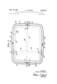
- FIG. 1 is a plan view of a studded cathode ray tube faceplate panel and apertured mask electrode together with a spacing fixture utilized in securing the studs to the p anel;
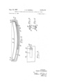
- FIG. 2 is a sectional view taken along line 22 of FIG. 1;
- FIG. 3 is an enlarged elevation view of a portion of the device of FIG. 1 taken along line 3-3 thereof;
- FIGS. 4 and 5 are sectional views of one of the mask mounting studs of FIG. 1 illustrating different process modifications and stages thereof in the securing of the studs to the panel.
- a cathode ray tube glass faceplate panel comprises a generally rectangular faceplate 12 and a side wall 14 extending from the periphery of the faceplate.
- the faceplate 12 is preferably curved, e.g., with an approximately spherical contour, as is known in the art.
- a plurality of electrode mounting studs 16 are attached to the interior surface of the panel side wall 14, preferably one near the mid-point of each of the two long sides 18 and the two short sides 20.
- each stud 16 comprises a hollow circular cup-shaped element having a tapered circular tip 22 forming the bottom of the cup.
- the frame 26 comprises a closed, generally rectangular rim having an L-shaped cross section.
- the masking member 28 comprises a shallow bowl-like multiapertured sheet of metal mounted across the frame 26.
- the mask member 28 has a surface contour which approximately matches the surface contour of the faceplate 12, for example, as described in US. Patent 3,109,116 issued to D. W. Epstein et al., on October 29, 1963.
- Each of the leaf springs 30 see particularly FIG.
- the aperture 32 is preferably of a generally triangular shape (FIG. 3), and the springs are so located that the apertures 32 receive the round tapered tips 22 of the studs 16 in a three point contact (or three small area contacts) therewith.
- the studs are preferably prepared by providing them with a precoating of a bonding agent such as a devitrifiable glass frit.
- a bonding agent such as a devitrifiable glass frit.
- the cup shaped stud 16 is filled with a slurry of glass frit suspended in a binder such as nitrocellulose.
- the stud 16 and frit slurry are then heated to a temperature sufficient to volatize the binder and soften the frit to thereby cause it to glaze, or adhere to, the inner wall of the stud 16.
- the frit 34 is of such a quantity that when glazed to the stud 16 it substantially fills the large cup portion of the stud 16 and protrudes very slightly beyond the open end of the stud in a shallow mound 36.
- the shadow mask electrode 24, including the frame 26, the masking member 28, and the support springs 30 are provided as a unit and positioned on top of a spacer device 38 within a studless faceplate panel 10. Such method of positioning provides an extremely accurate strain-free spacing.
- the panel may be oriented open-end-up as shown in FIG. 2 so that gravity urges the mask electrode 24 against the spacer 38 and the spacer against the panel 10.
- the spacer device 38 includes a T-shaped member whose three arms 39, 40, 41 extend to points adjacent to the panel side wall 14. Spacer pads 42 are provided near the ends of the arms 39, 40, 41 and extend therefrom to contact the faceplate 12.
- Mask-support brackets 44 are attached to the ends of the spacer arms 39, 40, 41 for receiving the mask electrode 24 in desired spaced relationship with the faceplate 12.
- the assembly of the panel 10, spacer 38, and mask electrode 24 may be inverted with the mask electrode being supported and the panel resting thereupon.
- the frit coated studs 16 are inserted between the support springs 30 and the panel side wall 14, with the tapered tips 22 received within the apertures 32 of the support springs and with the frit mounds 36 in contact with the interior surface of the panel side wall 14. In such an arrangement, the frit coated studs 16 are urged by the support springs 30 against the panel side wall 14.
- the entire assembly of faceplate panel 10, mask electrode 24, and studs 16 is then heated to resoften the frit coating on the studs 16.
- the particular time and temperature schedule to produce a softening of the frit is dependent upon the particular type of frit used. After the frit has become softened and the studs 16 pressed into place against the panel side wall 14, the frit is allowed to solidify and permanently secure the studs to the panel side Wall. In the case of a devitrifiable frit such as that marketed by the Corning Glass Company and identified by them as 7572, the solidification of the frit may occur at an elevated temperature. Such a devitrifiable frit is preferred because of its subsequent resistance to high temperature treatment during later processing of the cathode ray tube. In the case of a non-devitrifiable frit, the assembly of faceplate panel, mask electrode, and studs is cooled to produce a solidification of the frit.
- the above-described method of attaching the studs 16 to the panel 10 may be used to secure either all of the studs or any partial number of them, to a faceplate panel.
- a 4-stud panel three of the studs may be sealed into the panel by a prior art method, and the mask electrode may be provided with its four support springs. Then the mask may be supported within the panel with three of the support springs mounted on the three existing studs, and the fourth stud may then be frit sealed to the panel as hereinbefore described.
- the spacing device 38 may be dispensed with since the mask can be supported in place within the panel on the three existing studs during sealing-in of the fourth stud.
- both the mask 24 and the panel 10 can be conveniently heated simultaneously to a heat-stabilizing temperature as high as or higher than that to which they will be heated in subsequent processing or operation of the tube.
- This heat-stabilizing heating causes stresses in the mask and panel to be relieved and results in a relaxing and attendant minute reshaping of the mask and panel.
- Subsequent heatings of the mask and panel cause no significant additional stress relief and no reshaping of the mask and panel, as long as the subsequent heating does not raise the mask or panel to a temperature higher than the previous heat-stabilizing temperature.
- the mask and panel may be considered to be completely heatstabilized for subsequent normal processing and operation.
- heat stabilizing the mask and panel together they may be heat stabilized by separate hetaings.
- the glass panel it may be desirable and/ or convenient for the glass panel to be heat stabilized by the manufacturer of the panel.
- such a separate heat-stabilizing treatment of the panel should be at a temperature at least as high as the highest temperature to which it will be subsequently subjected by the tube manufacturer.
- the frit 34 may be provided as a pellet 46 as shown in FIG. 5.
- the pellet 46 may be inserted into a cup-shaped stud 16 a the time the stud is inserted in the apertures 32 a support spring 30.
- the first pellets are then held in place within the studs by the spring pressure urging them against the panel side wall 14. The bonding,
- the frit pellet 46 may be heated in its stud prior to assembly of the stud within the spring aperture to preglaze the frit of the pellet to the stud as shown in FIG. 4.
- the frit may be applied to the panel sidewall 14.
- the studs, with or without a coating of frit, are then pressed against the fritted areas of the side-wall.
- the frit may be provided in the form of an adhesive-backed tape comprising frit suspended in a solidified organic binder such as nitrocellulose.
- the frit may be applied to the panel side wall 14 over an area considerably larger than the stud. Such a large-area application of frit may serve to advantageously reduce stress concentration at the seal between the stud and panel.
- the faceplate panel may comprise a glass marketed by the Corning Glass Company and identified by them as 9019.
- the studs 16 may comprise industry standard N71 stainless steel, an alloy of principally nickel and iron, and the frit may comprise the devitrifiable 7572 frit referred to above.
- the precoating of the studs ⁇ 16 with the frit may be performed at 340400 C. and the subsequent softening and devitrifying of the frit coating on the stud performed at a temperature of 445 C.
- This invention has been disclosed by way of example, as embodying a particular design of multiapertured shadow mask electrode including a particular support spring design and a particular design of mask mounting studs. However, other designs of these elements may be used.
- means other than a glass frit as herein disclosed may be used to bond the studs to the faceplace panel.
- other bonding materials such as Sauereisen cement may be used.
- a selected area of the faceplate panel may be metalized and the studs soldered thereto.
- cathode ray tubes of the type comprising a faceplate panel having a plurality of studs attached thereto by heat-sealing which are received within the apertures of a plurality of spring supports attached to a mask electrode, the method of attaching said studs to said faceplate panel, said method comprising the steps of:
- a cathode ray tube of the type comprising a multiapertured sheet metal mask electrode which includes a plurality of apertured support springs at the periphery thereof, a shallow bowl-shaped faceplate panel including a face-plate portion and a peripheral side Wall portion, and a plurality of cup-shaped mounting studs secured to the internal surface of said side wall and received in the apertures of said support springs, the method of mounting said mask in said panel which method comprises the steps of:
- cathode ray tubes of the type comprising a faceplate panel and a multi-apertured mask electrode mounted on said panel in a predetermined spaced relation thereto, said panel including a mosaic phosphor screen comprising a multiplicity of elemental phosphor deposits critically positioned relative to the apertures of said mask electrode; the method comprising the steps of:
- step (a) said mask electrode is removably mounted on said panel in step (a) by 8 means of a plurality of spring supports secured to said mask electrode and having apertures engaging a like plurality of studs secured to said panel.
Landscapes
- Electrodes For Cathode-Ray Tubes (AREA)
- Vessels, Lead-In Wires, Accessory Apparatuses For Cathode-Ray Tubes (AREA)
- Manufacture Of Electron Tubes, Discharge Lamp Vessels, Lead-In Wires, And The Like (AREA)
Priority Applications (39)
| Application Number | Priority Date | Filing Date | Title |
|---|---|---|---|
| US374755A US3308327A (en) | 1964-06-12 | 1964-06-12 | Cathode ray tube |
| US374587A US3334259A (en) | 1964-06-12 | 1964-06-12 | Shadow mask mounting structure |
| US374691A US3335479A (en) | 1964-06-12 | 1964-06-12 | Method of fabricating and processing cathode ray tubes |
| US409261A US3296625A (en) | 1964-06-12 | 1964-11-05 | Cathode ray tube with electrode supported by strap-like springs |
| US409190A US3296477A (en) | 1964-06-12 | 1964-11-05 | Cathode ray tube with electrode supported by strap-like springs |
| GB25029/65A GB1084588A (en) | 1964-06-12 | 1965-05-27 | Improvements in and relating to the fabrication of cathode ray tubes |
| GB22902/65A GB1109001A (en) | 1964-06-12 | 1965-05-28 | Cathode ray tube structures and methods of making the structures |
| DE19651514352 DE1514352B1 (de) | 1964-06-12 | 1965-06-05 | Verfahren zur Montage der Lochmaske einer Bildroehr |
| FR19827A FR1435690A (fr) | 1964-06-12 | 1965-06-08 | Perfectionnements aux tubes à rayons cathodiques |
| GB24151/65A GB1115313A (en) | 1964-06-12 | 1965-06-08 | Cathode ray tube |
| FR19828A FR1435691A (fr) | 1964-06-12 | 1965-06-08 | Tube cathodique perfectionné et son procédé de fabrication |
| DK289365AA DK122553B (da) | 1964-06-12 | 1965-06-09 | Katodestrålerør. |
| FR20019A FR1436440A (fr) | 1964-06-12 | 1965-06-09 | Procédé pour la fabrication de plaques frontales de tubes à rayons cathodiques |
| DK289565AA DK121388B (da) | 1964-06-12 | 1965-06-09 | Fremgangsmåde til varmestabilisering af en med åbninger forsynet elektrode og et frontpladepanel til et katodestrålerør. |
| DE19651789070 DE1789070C2 (de) | 1964-06-12 | 1965-06-10 | Verfahren zum Befestigen von Tragstiften am inneren Rande der Frontplatte einer Kathodenstrahlröhre zur Wiedergabe farbiger Fernsehbilder |
| DE1965R0040845 DE1288691C2 (de) | 1964-06-12 | 1965-06-10 | Verfahren zur waermestabilisierung einer lochmasken-frontplatten-anordnung fuer eine kathodenstrahlroehre zur wiedergabe farbiger fernsehbilder |
| ES0314041A ES314041A1 (es) | 1964-06-12 | 1965-06-10 | El metodo de montar un electrodo dentro de un panel de cara frontal de un tubo de rayo catodico. |
| SE7730/65A SE306350B (index.php) | 1964-06-12 | 1965-06-11 | |
| AT528565A AT257705B (de) | 1964-06-12 | 1965-06-11 | Verfahren zur Befestigung einer Elektrode innerhalb einer Frontplattenschüssel einer Kathodenstrahlröhre |
| DER40856A DE1286540B (de) | 1964-06-12 | 1965-06-11 | Farbbildroehre |
| NL656507481A NL148182B (nl) | 1964-06-12 | 1965-06-11 | Werkwijze voor het vervaardigen van een samenstel van een glazen frontplaatpaneel voor een kathodestraalbuis met een mozaiekscherm van fosforneerslagen en een geperforeerde maskerelektrode, en samenstel vervaardigd volgens deze werkwijze. |
| BE665325A BE665325A (index.php) | 1964-06-12 | 1965-06-11 | |
| DK295065AA DK118513B (da) | 1964-06-12 | 1965-06-11 | Katodestrålerør. |
| SE7731/65A SE308735B (index.php) | 1964-06-12 | 1965-06-11 | |
| NL656507480A NL145094B (nl) | 1964-06-12 | 1965-06-11 | Werkwijze voor het vervaardigen van een kathodestraalbuis voor kleurentelevisie en kathodestraalbuis vervaardigd door toepassing van deze werkwijze. |
| BE665326D BE665326A (index.php) | 1964-06-12 | 1965-06-11 | |
| BE665321A BE665321A (index.php) | 1964-06-12 | 1965-06-11 | |
| DE19651437838 DE1437838B2 (de) | 1964-06-12 | 1965-06-11 | Kathodenstrahlröhre zur Farbbildwiedergabe mit einer Lochmaskenelektrode, die entfernbar in einem vorgeschriebenen Abstand von der Frontplatte der Röhre montiert ist und Verfahren zur Montage der Lochmaske |
| DK295165AA DK121523B (da) | 1964-06-12 | 1965-06-11 | Fremgangsmåde til fremstilling af et katodestrålerør. |
| BE665322A BE665322A (index.php) | 1964-06-12 | 1965-06-11 | |
| FR20410A FR1436497A (fr) | 1964-06-12 | 1965-06-11 | Perfectionnements aux tubes à rayons cathodiques |
| NL656507483A NL148436B (nl) | 1964-06-12 | 1965-06-11 | Werkwijze voor het vervaardigen van een elektronenstraalbuis, alsmede elektronenstraalbuis vervaardigd onder toepassing van deze werkwijze. |
| GB19471/65A GB1120331A (en) | 1964-06-12 | 1965-06-12 | Methods of fabricating and processing cathode ray tubes |
| GB6359/68A GB1120332A (en) | 1964-06-12 | 1965-06-12 | Methods of fabricating and processing cathode ray tubes |
| NL656507566A NL139147B (nl) | 1964-06-12 | 1965-06-14 | Kleurentelevisieweergeefbuis. |
| DK266769AA DK119215B (da) | 1964-06-12 | 1969-05-16 | Fremgangsmåde ved fremstilling af et katodestrålerør med en maskeelektrode eller en tilsvarende elektrode, der er aftageligt fastholdt i frontpladepanelet. |
| DK391870AA DK120809B (da) | 1964-06-12 | 1970-07-28 | Katodestrålerør med en bag frontpanelet af fjedre og tappe båret elektrode. |
| NL727200523A NL149632B (nl) | 1964-06-12 | 1972-01-13 | Werkwijze voor het vervaardigen van een samenstel van een glazen frontplaatpaneel voor een elektronenstraalbuis en een geperforeerde maskerelektrode, alsmede samenstel vervaardigd overeenkomstig deze werkwijze. |
| NL737305215A NL143366B (nl) | 1964-06-12 | 1973-04-13 | Kleurentelevisieweergeefbuis. |
Applications Claiming Priority (5)
| Application Number | Priority Date | Filing Date | Title |
|---|---|---|---|
| US374587A US3334259A (en) | 1964-06-12 | 1964-06-12 | Shadow mask mounting structure |
| US374755A US3308327A (en) | 1964-06-12 | 1964-06-12 | Cathode ray tube |
| US374691A US3335479A (en) | 1964-06-12 | 1964-06-12 | Method of fabricating and processing cathode ray tubes |
| US409261A US3296625A (en) | 1964-06-12 | 1964-11-05 | Cathode ray tube with electrode supported by strap-like springs |
| US409190A US3296477A (en) | 1964-06-12 | 1964-11-05 | Cathode ray tube with electrode supported by strap-like springs |
Publications (1)
| Publication Number | Publication Date |
|---|---|
| US3335479A true US3335479A (en) | 1967-08-15 |
Family
ID=27541342
Family Applications (5)
| Application Number | Title | Priority Date | Filing Date |
|---|---|---|---|
| US374691A Expired - Lifetime US3335479A (en) | 1964-06-12 | 1964-06-12 | Method of fabricating and processing cathode ray tubes |
| US374755A Expired - Lifetime US3308327A (en) | 1964-06-12 | 1964-06-12 | Cathode ray tube |
| US374587A Expired - Lifetime US3334259A (en) | 1964-06-12 | 1964-06-12 | Shadow mask mounting structure |
| US409261A Expired - Lifetime US3296625A (en) | 1964-06-12 | 1964-11-05 | Cathode ray tube with electrode supported by strap-like springs |
| US409190A Expired - Lifetime US3296477A (en) | 1964-06-12 | 1964-11-05 | Cathode ray tube with electrode supported by strap-like springs |
Family Applications After (4)
| Application Number | Title | Priority Date | Filing Date |
|---|---|---|---|
| US374755A Expired - Lifetime US3308327A (en) | 1964-06-12 | 1964-06-12 | Cathode ray tube |
| US374587A Expired - Lifetime US3334259A (en) | 1964-06-12 | 1964-06-12 | Shadow mask mounting structure |
| US409261A Expired - Lifetime US3296625A (en) | 1964-06-12 | 1964-11-05 | Cathode ray tube with electrode supported by strap-like springs |
| US409190A Expired - Lifetime US3296477A (en) | 1964-06-12 | 1964-11-05 | Cathode ray tube with electrode supported by strap-like springs |
Country Status (8)
| Country | Link |
|---|---|
| US (5) | US3335479A (index.php) |
| BE (4) | BE665321A (index.php) |
| DE (4) | DE1514352B1 (index.php) |
| DK (6) | DK121388B (index.php) |
| FR (3) | FR1435691A (index.php) |
| GB (5) | GB1084588A (index.php) |
| NL (4) | NL148436B (index.php) |
| SE (2) | SE306350B (index.php) |
Cited By (11)
| Publication number | Priority date | Publication date | Assignee | Title |
|---|---|---|---|---|
| US3357767A (en) * | 1967-03-01 | 1967-12-12 | Sylvania Electric Prod | Cathode ray tube fabrication |
| US3468005A (en) * | 1966-09-20 | 1969-09-23 | Sylvania Electric Prod | Process for improving mask-screen registration in cathode ray tubes |
| US3482286A (en) * | 1966-01-07 | 1969-12-09 | Rca Corp | Cathode ray tube manufacture |
| US3537161A (en) * | 1968-11-19 | 1970-11-03 | Sylvania Electric Prod | Process for achieving custom mask to panel spacing in cathode ray tubes |
| US3537159A (en) * | 1968-11-19 | 1970-11-03 | Sylvania Electric Prod | Apparatus for achieving custom mask to panel spacing in cathode ray tubes |
| US3672014A (en) * | 1970-12-24 | 1972-06-27 | Rca Corp | Method of mounting a mass in a cathode-ray tube using retractable spacing units |
| US3701193A (en) * | 1971-03-05 | 1972-10-31 | Rca Corp | Method of assembling and mounting an aperture mask in a mask-panel assembly of a cathode-ray tube using a full surface spacer |
| US3701185A (en) * | 1971-01-18 | 1972-10-31 | Rca Corp | Method of assembling a mask with a frame assembly for mounting in a cathode-ray tube using a remote assembly position |
| US3921024A (en) * | 1973-06-14 | 1975-11-18 | Philips Corp | Color selection electrode mount with coating of ductile metal |
| US4058875A (en) * | 1976-08-18 | 1977-11-22 | Rca Corporation | Method of assembling a mask-panel assembly of a shadow-mask cathode-ray tube |
| US4605878A (en) * | 1983-05-31 | 1986-08-12 | Sony Corporation | Supporting device for an electron beam landing position selecting mask of a color cathode ray tube |
Families Citing this family (25)
| Publication number | Priority date | Publication date | Assignee | Title |
|---|---|---|---|---|
| US3449611A (en) * | 1966-06-22 | 1969-06-10 | Nat Video Corp | Suspension system for color television tube mask |
| NL6616317A (index.php) * | 1966-11-19 | 1968-05-20 | ||
| US3492522A (en) * | 1967-08-15 | 1970-01-27 | Zenith Radio Corp | Shadow mask supported by v-shaped springs having apices directed toward gun |
| US3562517A (en) * | 1967-10-03 | 1971-02-09 | Nat Video Corp | Shadow mask mounting system for color kinescope including one side direct connection |
| US3898508A (en) * | 1968-12-19 | 1975-08-05 | Zenith Radio Corp | Temperature compensated shadow mask for a color cathode-ray tube |
| US3610990A (en) * | 1969-04-18 | 1971-10-05 | Hitachi Ltd | Leaf spring arrangement for color selection electrode |
| US3553517A (en) * | 1969-04-21 | 1971-01-05 | Sylvania Electric Prod | Support means for a color cathode ray tube shadow mask member having smooth circumferential seating contact |
| US3619689A (en) * | 1970-04-06 | 1971-11-09 | Rca Corp | Cathode-ray tube with electrode supported by straplike springs |
| US3700948A (en) * | 1970-07-09 | 1972-10-24 | Motorola Inc | Edge-bonded bi-metallic strip extending from metal plate on shadow mask to stud via spring of substantially smaller cross-sectional area than strip |
| US3832592A (en) * | 1971-07-05 | 1974-08-27 | Hitachi Ltd | Mask electrode support for color picture tube |
| NL7510970A (nl) * | 1975-09-18 | 1977-03-22 | Philips Nv | Kathodestraalbuis. |
| NL8004173A (nl) * | 1980-07-21 | 1982-02-16 | Philips Nv | Kleurenbeeldbuis. |
| DE3035368A1 (de) * | 1980-09-19 | 1982-05-06 | Licentia Patent-Verwaltungs-Gmbh, 6000 Frankfurt | Farbbildkathodenstrahlroehre |
| NL8102182A (nl) * | 1981-05-04 | 1982-12-01 | Philips Nv | Kleurenbeeldbuis. |
| US4460843A (en) * | 1982-04-29 | 1984-07-17 | Rca Corporation | Color picture tube having improved temperature compensating support for a mask-frame assembly |
| US4467242A (en) * | 1982-10-18 | 1984-08-21 | Rca Corporation | Color selection electrode mounting structure having an off-set washer |
| US4500767A (en) * | 1983-07-27 | 1985-02-19 | Rca Corporation | Shadow mask washer/spring welding apparatus |
| US4604072A (en) * | 1984-07-03 | 1986-08-05 | Rca Corporation | Method for engaging support studs into shadow mask spring apparatus |
| JP2577361B2 (ja) * | 1985-09-25 | 1997-01-29 | 株式会社東芝 | カラ−受像管 |
| JP2965254B2 (ja) * | 1988-01-22 | 1999-10-18 | 株式会社東芝 | カラー受像管の製造方法 |
| US4992067A (en) * | 1989-10-25 | 1991-02-12 | Rca Licensing Corp. | Method of manufacturing a color cathode-ray tube |
| US5128585A (en) * | 1990-03-16 | 1992-07-07 | Thomson Consumer Electronics, Inc. | Color picture tube having improved corner support for a shadow mask-frame assembly |
| JP3516462B2 (ja) * | 1993-05-20 | 2004-04-05 | ソニー株式会社 | 陰極線管の製造方法 |
| KR100585524B1 (ko) * | 2003-05-12 | 2006-06-07 | 엘지.필립스 디스플레이 주식회사 | 칼라 음극선관용 홀더 및 그 제조 방법 |
| KR101996437B1 (ko) * | 2012-10-16 | 2019-07-05 | 삼성디스플레이 주식회사 | 투명 보호창, 이를 포함하는 가요성 표시 장치 및 투명 보호창의 제조 방법 |
Citations (8)
| Publication number | Priority date | Publication date | Assignee | Title |
|---|---|---|---|---|
| US2546828A (en) * | 1950-02-17 | 1951-03-27 | Nat Union Radio Corp | Target assembly for cathode-ray tubes |
| US2727172A (en) * | 1954-08-18 | 1955-12-13 | Rca Corp | Electrode support for cathode-ray color tube |
| US2846608A (en) * | 1954-09-14 | 1958-08-05 | Rca Corp | Cathode-ray tube |
| US2871087A (en) * | 1956-02-10 | 1959-01-27 | Westinghouse Electric Corp | Method of assembling a color television tube |
| US2878623A (en) * | 1956-09-14 | 1959-03-24 | Owens Illinois Glass Co | Method of attaching metal brackets to glass |
| US2922063A (en) * | 1956-11-07 | 1960-01-19 | Sylvania Electric Prod | Target assembly for cathode ray tubes |
| US2928967A (en) * | 1956-09-13 | 1960-03-15 | Owens Illinois Glass Co | Brackets for glass parts and method of attachment |
| US3187404A (en) * | 1962-01-11 | 1965-06-08 | Rauland Corp | Method of manufacture of color television picture tube |
Family Cites Families (8)
| Publication number | Priority date | Publication date | Assignee | Title |
|---|---|---|---|---|
| US1994251A (en) * | 1934-03-02 | 1935-03-12 | Mueller Electric Company | Connecter |
| US2961560A (en) * | 1955-05-06 | 1960-11-22 | Columbia Broadcasting Syst Inc | Color picture tube |
| US2856552A (en) * | 1956-03-15 | 1958-10-14 | Gen Electric | Grille structure for television picture tubes |
| NL216226A (index.php) * | 1956-04-17 | |||
| US2823328A (en) * | 1956-04-20 | 1958-02-11 | Owensillinois Glass Company | Mounting for color-control elements in cathode-ray tubes |
| US3004182A (en) * | 1958-03-13 | 1961-10-10 | Owens Illinois Glass Co | Mounting element and method of attachment to glass |
| US2951167A (en) * | 1958-06-26 | 1960-08-30 | Kimble Glass Co | Support means for mounting color-control element in glass portion of cathode-ray tube envelope |
| US3034009A (en) * | 1960-01-18 | 1962-05-08 | Gen Electric | Pin seal accelerator tubes |
-
1964
- 1964-06-12 US US374691A patent/US3335479A/en not_active Expired - Lifetime
- 1964-06-12 US US374755A patent/US3308327A/en not_active Expired - Lifetime
- 1964-06-12 US US374587A patent/US3334259A/en not_active Expired - Lifetime
- 1964-11-05 US US409261A patent/US3296625A/en not_active Expired - Lifetime
- 1964-11-05 US US409190A patent/US3296477A/en not_active Expired - Lifetime
-
1965
- 1965-05-27 GB GB25029/65A patent/GB1084588A/en not_active Expired
- 1965-05-28 GB GB22902/65A patent/GB1109001A/en not_active Expired
- 1965-06-05 DE DE19651514352 patent/DE1514352B1/de active Pending
- 1965-06-08 FR FR19828A patent/FR1435691A/fr not_active Expired
- 1965-06-08 FR FR19827A patent/FR1435690A/fr not_active Expired
- 1965-06-08 GB GB24151/65A patent/GB1115313A/en not_active Expired
- 1965-06-09 DK DK289565AA patent/DK121388B/da unknown
- 1965-06-09 DK DK289365AA patent/DK122553B/da unknown
- 1965-06-10 DE DE1965R0040845 patent/DE1288691C2/de not_active Expired
- 1965-06-11 DE DER40856A patent/DE1286540B/de active Pending
- 1965-06-11 FR FR20410A patent/FR1436497A/fr not_active Expired
- 1965-06-11 DK DK295065AA patent/DK118513B/da unknown
- 1965-06-11 NL NL656507483A patent/NL148436B/xx not_active IP Right Cessation
- 1965-06-11 NL NL656507480A patent/NL145094B/xx not_active IP Right Cessation
- 1965-06-11 BE BE665321A patent/BE665321A/xx unknown
- 1965-06-11 SE SE7730/65A patent/SE306350B/xx unknown
- 1965-06-11 SE SE7731/65A patent/SE308735B/xx unknown
- 1965-06-11 NL NL656507481A patent/NL148182B/xx not_active IP Right Cessation
- 1965-06-11 DK DK295165AA patent/DK121523B/da unknown
- 1965-06-11 BE BE665325A patent/BE665325A/xx unknown
- 1965-06-11 DE DE19651437838 patent/DE1437838B2/de active Pending
- 1965-06-11 BE BE665326D patent/BE665326A/xx unknown
- 1965-06-11 BE BE665322A patent/BE665322A/xx unknown
- 1965-06-12 GB GB6359/68A patent/GB1120332A/en not_active Expired
- 1965-06-12 GB GB19471/65A patent/GB1120331A/en not_active Expired
- 1965-06-14 NL NL656507566A patent/NL139147B/xx not_active IP Right Cessation
-
1969
- 1969-05-16 DK DK266769AA patent/DK119215B/da unknown
-
1970
- 1970-07-28 DK DK391870AA patent/DK120809B/da unknown
Patent Citations (8)
| Publication number | Priority date | Publication date | Assignee | Title |
|---|---|---|---|---|
| US2546828A (en) * | 1950-02-17 | 1951-03-27 | Nat Union Radio Corp | Target assembly for cathode-ray tubes |
| US2727172A (en) * | 1954-08-18 | 1955-12-13 | Rca Corp | Electrode support for cathode-ray color tube |
| US2846608A (en) * | 1954-09-14 | 1958-08-05 | Rca Corp | Cathode-ray tube |
| US2871087A (en) * | 1956-02-10 | 1959-01-27 | Westinghouse Electric Corp | Method of assembling a color television tube |
| US2928967A (en) * | 1956-09-13 | 1960-03-15 | Owens Illinois Glass Co | Brackets for glass parts and method of attachment |
| US2878623A (en) * | 1956-09-14 | 1959-03-24 | Owens Illinois Glass Co | Method of attaching metal brackets to glass |
| US2922063A (en) * | 1956-11-07 | 1960-01-19 | Sylvania Electric Prod | Target assembly for cathode ray tubes |
| US3187404A (en) * | 1962-01-11 | 1965-06-08 | Rauland Corp | Method of manufacture of color television picture tube |
Cited By (11)
| Publication number | Priority date | Publication date | Assignee | Title |
|---|---|---|---|---|
| US3482286A (en) * | 1966-01-07 | 1969-12-09 | Rca Corp | Cathode ray tube manufacture |
| US3468005A (en) * | 1966-09-20 | 1969-09-23 | Sylvania Electric Prod | Process for improving mask-screen registration in cathode ray tubes |
| US3357767A (en) * | 1967-03-01 | 1967-12-12 | Sylvania Electric Prod | Cathode ray tube fabrication |
| US3537161A (en) * | 1968-11-19 | 1970-11-03 | Sylvania Electric Prod | Process for achieving custom mask to panel spacing in cathode ray tubes |
| US3537159A (en) * | 1968-11-19 | 1970-11-03 | Sylvania Electric Prod | Apparatus for achieving custom mask to panel spacing in cathode ray tubes |
| US3672014A (en) * | 1970-12-24 | 1972-06-27 | Rca Corp | Method of mounting a mass in a cathode-ray tube using retractable spacing units |
| US3701185A (en) * | 1971-01-18 | 1972-10-31 | Rca Corp | Method of assembling a mask with a frame assembly for mounting in a cathode-ray tube using a remote assembly position |
| US3701193A (en) * | 1971-03-05 | 1972-10-31 | Rca Corp | Method of assembling and mounting an aperture mask in a mask-panel assembly of a cathode-ray tube using a full surface spacer |
| US3921024A (en) * | 1973-06-14 | 1975-11-18 | Philips Corp | Color selection electrode mount with coating of ductile metal |
| US4058875A (en) * | 1976-08-18 | 1977-11-22 | Rca Corporation | Method of assembling a mask-panel assembly of a shadow-mask cathode-ray tube |
| US4605878A (en) * | 1983-05-31 | 1986-08-12 | Sony Corporation | Supporting device for an electron beam landing position selecting mask of a color cathode ray tube |
Also Published As
Similar Documents
| Publication | Publication Date | Title |
|---|---|---|
| US3335479A (en) | Method of fabricating and processing cathode ray tubes | |
| US3330980A (en) | Shadow mask mounted with bi-metallic sections connected by expansible loop | |
| US4451759A (en) | Flat viewing screen with spacers between support plates and method of producing same | |
| US2951167A (en) | Support means for mounting color-control element in glass portion of cathode-ray tube envelope | |
| US2755405A (en) | Color television tube | |
| US4891546A (en) | Front assembly for a tension mask color cathode ray tube having a laser-deflecting shadow mask support structure | |
| US4891545A (en) | Faceplate front assembly with improved tension mask support structure | |
| US4652791A (en) | Color cathode ray tube and tensible shadow mask blank for use therein | |
| US3537161A (en) | Process for achieving custom mask to panel spacing in cathode ray tubes | |
| US3735179A (en) | Face panel assembly for color cathode-ray tube | |
| US4923422A (en) | Process for an improved tension mask support structure | |
| US3986760A (en) | Method for manufacturing a multi-digit fluorescent indicating apparatus | |
| US3787937A (en) | Method of processing a color cathode-ray tube | |
| US3468005A (en) | Process for improving mask-screen registration in cathode ray tubes | |
| US4866334A (en) | CRT faceplate front assembly with rigidized tension mask support structure | |
| US4713034A (en) | Means and method for manufacture of a high-resolution color cathode ray tube | |
| US3796903A (en) | Connecting member in post focusing type colour picture tubes | |
| US4400644A (en) | Self-indexing insulating support rods for an electron gun assembly | |
| US6249266B1 (en) | Fluorescent display device and process for manufacturing same | |
| US2928967A (en) | Brackets for glass parts and method of attachment | |
| US2821644A (en) | Mountings for picture tube grids | |
| US4071932A (en) | Method of making electron guns for cathode ray tubes and the like | |
| US2141387A (en) | Electron discharge device | |
| US3710165A (en) | Shadow mask perforated along intersection of side wall and reinforcing flange | |
| US3737065A (en) | Envelope for, and method of processing, a color cathode-ray tube |