US3672014A - Method of mounting a mass in a cathode-ray tube using retractable spacing units - Google Patents
Method of mounting a mass in a cathode-ray tube using retractable spacing units Download PDFInfo
- Publication number
- US3672014A US3672014A US101315A US3672014DA US3672014A US 3672014 A US3672014 A US 3672014A US 101315 A US101315 A US 101315A US 3672014D A US3672014D A US 3672014DA US 3672014 A US3672014 A US 3672014A
- Authority
- US
- United States
- Prior art keywords
- mask
- panel
- spacing
- faceplate
- frame
- Prior art date
- Legal status (The legal status is an assumption and is not a legal conclusion. Google has not performed a legal analysis and makes no representation as to the accuracy of the status listed.)
- Expired - Lifetime
Links
Images
Classifications
-
- H—ELECTRICITY
- H01—ELECTRIC ELEMENTS
- H01J—ELECTRIC DISCHARGE TUBES OR DISCHARGE LAMPS
- H01J29/00—Details of cathode-ray tubes or of electron-beam tubes of the types covered by group H01J31/00
- H01J29/02—Electrodes; Screens; Mounting, supporting, spacing or insulating thereof
- H01J29/06—Screens for shielding; Masks interposed in the electron stream
- H01J29/07—Shadow masks for colour television tubes
- H01J29/073—Mounting arrangements associated with shadow masks
Definitions
- ABSTRACT The method includes positioning a mask-frame assembly in predetermined spaced relation with the inner surface of a faceplate of a cathodeqay tube by means of at least four [58] Fieid 25 11 13 15 retractable spacing units.
- the spacing units are each extended 3 a predetermined fixed distance, and the mask-frame assembly is mounted in the panel. Then the spacing units are retracted to allow the mask to be self-supporting in the panel, and the [56] Rem-mm cued spacing between the mask and the face-plate is measured at UNITED STATES PATENTS discrete positions without removing the retracted spacing units.
- Shadow-mask-type color picture tubes for television receivers which are well known include a curved faceplate having a mosaic screen of different color emissive phosphor dots and an electron gun to project plural electron beams towards the screen.
- a mask is nested behind the faceplate with a prescribed spacing from center to edge, such as described, for example, in U.S. Pat. No. 3,109,1l6to D. W. Epstein et al.
- the electron beams pass through apertures in the mask to selectively excite the phosphor dots.
- a q-spacing gauge member having multiple variable distance-measuring units is positioned on the inner concave surface of the faceplate.
- a maskframe assembly is inserted within the panel over the gauge member and temporarily mounted on the panel studs by means of leaf springs frictionally engaging hook plates attached to theframe.
- the mask is moved to the desired position and the q-distances are measured. After the desired qdistances are obtained, the leaf springs are welded to the hook plates on the frame and the inserted gauge is removed.
- This assembly method requires custom adjustment of the q-spacing for each panel assembly while reading each of the gauges, which is not suitable for economical production.
- the mask and hook plates are first attached to a frame to produce a mask-frame assembly.
- the a qspacer having a plurality of fixed distance spacing units is positioned on the inner concave surface of the faceplate.
- a maskframe assembly is inserted within the panel over the gauge member and temporarily mounted on the panel studs by means of leaf springs frictionally engaging the hook plates; and the leaf springs are welded to the hook plates on the frame.
- the mask-frame assembly and the spacer insert are removed; and a q-spacing gauge member is inserted in the panelqThe mask-frame assembly is then reinserted and the q distances are measured.
- This assembly method is lengthy. and may result in handling damage, such as dents in the mask.
- the novel method includes positioning a mask-frame assembly in spaced relation from a faceplate of a cathode-ray tube by means of at least four retractable spacing units.
- the spacing units are each extended to a predetermined fixed distance, and the mask-frame assembly is mounted in the panel.
- the spacing units are then retracted to allow the mask to be self-supporting in the panel, and the spacing between the mask and faceplate is measured at discrete positions without removing the retracted spacing units.
- the novel method provides for disengagement of the distance-spacing units during the measurement of the mask-to-faceplate spacing. This reduces errors resulting from stresses maintained in the mask from contact with the spacing units.
- the novel method thereby permits accurate measurement of spacing immediately after the mask is made self-supporting in the panel without removal and reinsertion of the mask-frame assembly. Also, variables which may result from removal of the mask to permit insertion of the variable distance-measuring means are not introduced prior to the measuring step.
- the novel method unlike previous methods, permits measurement of the q-spacings in a simple economical manner with less handling, and hence less chance of handling damage.
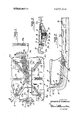
- FIG. 1 is a plan view of the apparatus used for practicing the novel method, positioned in a broken-away fragmentary portion of a panel assembly for a color-television picture tube.
- FIG. 2 is a partially sectional elevational view of the apparatus shown in FIG. 1, on section line 2-2 thereof, illustrating the mask self supported in the panel assembly.
- FIG. 3 is an enlarged view of a retractable spacing unit shown in FIG. 2, used in practicing the novel method.
- FIGS. 1 and 2 illustrate an apparatus 10 for positioning a mask in the panel assembly 1 l of a shadow-mask-type colortelevision picture tube.
- the panel assembly 11 includes a panel 12 and a mask-frame assembly 13.
- the panel 12 includes a faceplate 14 and a sidewall 15 having four studs 16 extending inwardly therefrom.
- the mask-frame assembly 13 includes a multi-apertured mask 17 having a perimetric skirt 18, a frame assembly 19, including a frame 20 having a vertically upstanding flange 21 parallel to the skirt l8 and four hook plates 22 attached to the frame 20.
- Frame support members comprising four leaf springs 23 are each attached at one end to one of the hook plates 22 and each has a hole 24 at the other end to detachably engage one of the four studs 16.
- the apparatus 10 for practicing the invention comprises a relatively thin rectangular curved sheet 25, such as a one-eighth-inch-thick sheet of fiberglass or plastic, having a contour conforming substantially to the contour of the faceplate surface.
- Guide members 26a through 26d which extend outwardly from the concave side of the sheet 25 substantially in the direction of the panel sidewall 15, are mounted on the corners of the sheet 25 as shown in FIGS. 1 and 2.
- Nine variable-distance-measuring gauges 27a through 27i' are flexibly mounted in openings through the sheet 25 in positions substantially as shown in FIG. 1.
- a suitable variabledistance-measuring gauge is and L-matic air gauge marketed by Moore Products Inc., Spring House, Pa.
- the gauges 27a through 271' are each connected by flexible tubes 28a through i 28: to fluid manometers 29a through 29i (only 29a is shown in in detail in FIG. 3, comprises a housing 31 mounted on the sheet 25 as shown in FIG. 3.
- the housing 31 includes a base member 32 and a retainer 33.
- a plunger assembly 34 is mounted for limited movement in the retainer 33.
- a flexible diaphragm 35 positioned between the base member 32 and the retainer 33 forms an air chamber 36 between the base member 32 and the diaphragm 35.
- a connecting tubing 370 through 37d connects the air chamber 36 in each of the spacing units 30a through 30d to a central air supply (not shown) through a common air valve (not shown).
- the plunger assembly 34 includes a plunger 38, a contact tip 39 adjustably mounted in the plunger 38, and a locking member 40 mounted in the contact tip 39.
- a panel 12 is positioned on a table in an inverted position with the open portion facing upwardly.
- the apparatus is inserted into the panel 12 oriented by the guide members 26a through 26d until the apparatus is supported on the faceplate 14 in substantial contact on all four contact tips 39.
- the guide members 26a through 26d also serve to position the apparatus 10 in an approximately centered location in the panel 12.
- a mask-frame assembly comprising frame 20 preassembled with a mask 17 and four hook plates 22 in a manner well known in the art is positioned on the apparatus 10 with the mask 17 substantially supported in continuous contact with and conforming with the concave side of the sheet 25.
- a weight member substantially conforming to the desired inner concave surface of the mask 17 may be positioned in the mask 17 to hold the mask in continuous contact with the sheet 25.
- a continuous contact it is meant that the contour variations in the mask 17 are averaged to obtain a substantially average contour conforming to the contour of the sheet 25.
- the plunger assemblies 34 are extended by operating a valve (not shown) to supply air to each of the air chambers 26.
- the air pressure in each of the air chambers 36 forces the flexible diaphragm 35 and plunger assembly 34 outward. Since the stroke of the plunger assembly 34 is limited by the retainer 33, the final extended position of the plunger assemblies 34 is fixed.
- the distance from the inner concave contour of the sheet 25 to the end of the contact tip 39 in the final extended position determines the desired spacing q-normal to the surface of the mask 17 between the faceplate 14 and mask 17.
- the desired spacing q is mathematically and empirically determined for each of the spacing units 300 through 30d from the geometric and electronic tube parameters in a well known manner.
- the spacing units 30a through 30d with the plunger assembly in the final extended position are adjusted to a predetermined fixed distance corresponding to the spacing q by moving the contact tip 39 in the plunger 38 and then locking the contact tip 39 to the plunger 38 by means of locking member 40. Therefore, once each of the spacing units 30a through 30d is adjusted to the predetermined fixed spacing, the apparatus is ready for use with the novel method.
- the spacing units 30a through 30d are bisymmetrically positioned as previously described, the desired spacing q is the same predetermined fixed distance for each of the spacing units 30a through 30d.
- Frame support members comprising four leaf springs 23 are then assembled with the four hook plates 22 on the frame and detachably engaged with the four studs 16 in the panel sidewall 15.
- the mask-frame assembly 13 is then attached in the panel 12 by welding the leaf springs 23 to the hook plates 22 in a manner well known in the art.
- the spacing units 30a through 30d are retracted by removing the air supply (not shown), and the weight of the apparatus 10 supported on the plunger assemblies 34 causes the plungers 38 to retract and the sheet to move away from contact with the mask 17. Once the sheet 25 is disengaged from contact with the mask 17, the mask 17 is solely supported by the panel 12 and any distortion introduced into the mask 17 by the apparatus 10 is removed.
- the spacing between the free-standing mask 17 and the faceplate 14 is measured at predetermined discrete locations without removing the spacing units a through 30b.
- nine gauges 27a through 271' are mounted on the sheet 25 as shown in FIG. 1.
- the gauges 27a through 271' are flexibly mounted to the sheet 25 as previously described to permit free movement during measurement of the spacing q.
- the measurement of the spacing q is obtained by reading the pressure variations on the fluid manometers 29a through 291 respectively for each gauge 27a through 27i on a calibrated scale.
- the mask-frame assembly 13 and the apparatus 10 are removed from the panel 12, and the mask-frame assembly 13 and panel 12 are identified as matched work pieces for further processing and reassembled to form the panel assembly 11.
- the spacing q is described as measured at nine positions, four positions can be measured, such as positions at gauges 27b, 27e, 27g and 271'.
- the spacing q may also be measured with the retractable spacing units 30a through 30b spacing the mask and faceplate, as previously described, prior to attachment, during attachment, or both before and after attachment, or any other measurement combination thereof.
- the measurement of spacing-q after attachment of the mask 17 in the panel 12, with the mask 17 standing free from the spacing apparatus and solely supported by the panel provides a quality-control check on the panel assembly prior to further processing. Panel assemblies having unsatisfactory spacings q from mounting the mask 17 in the panel 12, which may have resulted from the apparatus 10 or the attachment of the leaf springs 23, can be removed for salvage without subsequent processing, thereby eliminating further uneconomical waste.
- a cathode-ray tube including a substantially rectangularly shaped viewing panel having a contoured faceplate and a mask-frame assembly including a frame and a contoured mask
- the method of mounting the mask-frame assembly in the panel comprising a. positioning said mask in spaced relation with the inner surface of the faceplate by at least four retractable spacing units,
- said spacing units extend from the convex side of a flexible sheet substantially conforming to the contour of said mask, and said positioning step comprises positioning said mask on the concave side of said sheet in substantial average contact with said sheet and spaced from the inner surface of said panel by said retractable spacing units.
- said spacing units comprise four spacing units bisymmetrically positioned in said panel, and said extending step includes extending each of said spacing units by the same predetermined fixed distance.
- said attaching step comprises welding frame-support members to said mask-frame assembly for detachable engagement with said panel.
- said retracting step comprises moving said spacing units to displace said sheet away from said mask while maintaining said mask solely supported by said panel.
- a cathode-ray tube including a substantially rectangularly shaped panel having a contoured faceplate and a sidewall having support studs extending inwardly therefrom, a mask-frame assembly including a frame having hook plate members and a contoured mask attached to said frame and frame-support members attached to said hook plate members for engagement with each of said studs, the method of mounting said mask in said panel, the steps comprising a.
- an apparatus comprising a contoured sheet substantially conforming to the exterior convex contour of the mask with at least four retractable spacing means extending from the convex side of said sheet and contacting said faceplate, and at least four discretely positioned variable-distance-measuring gauges with one end of each gauge contacting said faceplate,
- each of said spacing means retracting each of said spacing means to a distance less than said predetermined fixed distance while maintaining contact with said faceplate to move said sheet away from said mask leaving said mask self-supported on said support members in said panel, and
- said spaced retractable spacing means comprises four retractable spacing means positioned bisymmetrically with said faceplate, and said extending step comprises extending said retractable spacing means to the same predetermined fixed distance.
Landscapes
- Formation Of Various Coating Films On Cathode Ray Tubes And Lamps (AREA)
- Manufacture Of Electron Tubes, Discharge Lamp Vessels, Lead-In Wires, And The Like (AREA)
- Measurement Of Radiation (AREA)
Abstract
The method includes positioning a mask-frame assembly in predetermined spaced relation with the inner surface of a faceplate of a cathode-ray tube by means of at least four retractable spacing units. The spacing units are each extended a predetermined fixed distance, and the mask-frame assembly is mounted in the panel. Then the spacing units are retracted to allow the mask to be self-supporting in the panel, and the spacing between the mask and the face-plate is measured at discrete positions without removing the retracted spacing units.
Description
United States Patent Kimbrough [451 June 27, 1972 [54] METHOD OF MOUNTING A MASS IN A 3,537,161 11/1970 Kautz ...29/2s.1s CATHODE-RAY TUBE USING 3,564,195 2/1971 Ploog ..29/25. 15 RETRACTABLE SPACING UNITS Primary hammer-John F. Campbell [72] Inventor: Laurence B. Kimbrough, Lititz, Pa. Assistant Examiner-Richard B. Lazarus [73] Assi RCA Cor oration Attorney-Glenn l-l. Bruestle and LeRoy Greenspan, Lewis L.
g P Floyd [22] Filed: Dec. 24, 1970 21 App]. No.: 101,315 [57] ABSTRACT The method includes positioning a mask-frame assembly in predetermined spaced relation with the inner surface of a faceplate of a cathodeqay tube by means of at least four [58] Fieid 25 11 13 15 retractable spacing units. The spacing units are each extended 3 a predetermined fixed distance, and the mask-frame assembly is mounted in the panel. Then the spacing units are retracted to allow the mask to be self-supporting in the panel, and the [56] Rem-mm cued spacing between the mask and the face-plate is measured at UNITED STATES PATENTS discrete positions without removing the retracted spacing units. 3,335,479 8/1967 Morrell ..29/25.13 3,482,286 12/1969 Fassett et a1 ..29/25. 13 9 Claims, 3 Drawing Figures 1 METHOD OF MOUNTING A MASS IN A CATI-IODE-RAY TUBE USING RETRACTABLE SPACING UNITS BACKGROUND OF THE INVENTION The invention relates to a method of mounting an aperture mask in a particular spaced relationship in the faceplate panel of a cathode-ray tube, and particularly a rectangular colortelevision picture tube.
Commercial rectangular shadow-mask-type color picture tubes for television receivers which are well known include a curved faceplate having a mosaic screen of different color emissive phosphor dots and an electron gun to project plural electron beams towards the screen. A mask is nested behind the faceplate with a prescribed spacing from center to edge, such as described, for example, in U.S. Pat. No. 3,109,1l6to D. W. Epstein et al. In the operation of the tube, the electron beams pass through apertures in the mask to selectively excite the phosphor dots. I
In one prior method for mounting a mask in a color-televi sion picture tube, described, for example, in U.S. Pat. No. 3,482,286 to G. F. Fassett et al., a q-spacing gauge member having multiple variable distance-measuring units is positioned on the inner concave surface of the faceplate. A maskframe assembly is inserted within the panel over the gauge member and temporarily mounted on the panel studs by means of leaf springs frictionally engaging hook plates attached to theframe. The mask is moved to the desired position and the q-distances are measured. After the desired qdistances are obtained, the leaf springs are welded to the hook plates on the frame and the inserted gauge is removed. This assembly method requires custom adjustment of the q-spacing for each panel assembly while reading each of the gauges, which is not suitable for economical production.
In another prior method for mounting a mask in a colortelevision picture tube, the mask and hook plates are first attached to a frame to produce a mask-frame assembly. The a qspacer having a plurality of fixed distance spacing units is positioned on the inner concave surface of the faceplate. A maskframe assembly is inserted within the panel over the gauge member and temporarily mounted on the panel studs by means of leaf springs frictionally engaging the hook plates; and the leaf springs are welded to the hook plates on the frame. The mask-frame assembly and the spacer insert are removed; and a q-spacing gauge member is inserted in the panelqThe mask-frame assembly is then reinserted and the q distances are measured. This assembly method is lengthy. and may result in handling damage, such as dents in the mask.
SUMMARY OF THE INVENTION The novel method includes positioning a mask-frame assembly in spaced relation from a faceplate of a cathode-ray tube by means of at least four retractable spacing units. The spacing units are each extended to a predetermined fixed distance, and the mask-frame assembly is mounted in the panel. The spacing units are then retracted to allow the mask to be self-supporting in the panel, and the spacing between the mask and faceplate is measured at discrete positions without removing the retracted spacing units.
By using retractable spacing units, the novel method provides for disengagement of the distance-spacing units during the measurement of the mask-to-faceplate spacing. This reduces errors resulting from stresses maintained in the mask from contact with the spacing units. The novel method thereby permits accurate measurement of spacing immediately after the mask is made self-supporting in the panel without removal and reinsertion of the mask-frame assembly. Also, variables which may result from removal of the mask to permit insertion of the variable distance-measuring means are not introduced prior to the measuring step. The novel method, unlike previous methods, permits measurement of the q-spacings in a simple economical manner with less handling, and hence less chance of handling damage.
BRIEF DESCRIPTION OF THE DRAWINGS FIG. 1 is a plan view of the apparatus used for practicing the novel method, positioned in a broken-away fragmentary portion of a panel assembly for a color-television picture tube.
FIG. 2 is a partially sectional elevational view of the apparatus shown in FIG. 1, on section line 2-2 thereof, illustrating the mask self supported in the panel assembly.
FIG. 3 is an enlarged view of a retractable spacing unit shown in FIG. 2, used in practicing the novel method.
DESCRIPTION OF THE PREFERRED EMBODIMENT FIGS. 1 and 2 illustrate an apparatus 10 for positioning a mask in the panel assembly 1 l of a shadow-mask-type colortelevision picture tube. The panel assembly 11 includes a panel 12 and a mask-frame assembly 13. The panel 12 includes a faceplate 14 and a sidewall 15 having four studs 16 extending inwardly therefrom. The mask-frame assembly 13 includes a multi-apertured mask 17 having a perimetric skirt 18, a frame assembly 19, including a frame 20 having a vertically upstanding flange 21 parallel to the skirt l8 and four hook plates 22 attached to the frame 20. Frame support members comprising four leaf springs 23 are each attached at one end to one of the hook plates 22 and each has a hole 24 at the other end to detachably engage one of the four studs 16.
In this example, the apparatus 10 for practicing the invention comprises a relatively thin rectangular curved sheet 25, such as a one-eighth-inch-thick sheet of fiberglass or plastic, having a contour conforming substantially to the contour of the faceplate surface. Guide members 26a through 26d, which extend outwardly from the concave side of the sheet 25 substantially in the direction of the panel sidewall 15, are mounted on the corners of the sheet 25 as shown in FIGS. 1 and 2. Nine variable-distance-measuring gauges 27a through 27i'are flexibly mounted in openings through the sheet 25 in positions substantially as shown in FIG. 1. A suitable variabledistance-measuring gauge is and L-matic air gauge marketed by Moore Products Inc., Spring House, Pa. The gauges 27a through 271' are each connected by flexible tubes 28a through i 28: to fluid manometers 29a through 29i (only 29a is shown in in detail in FIG. 3, comprises a housing 31 mounted on the sheet 25 as shown in FIG. 3. The housing 31 includes a base member 32 and a retainer 33. A plunger assembly 34 is mounted for limited movement in the retainer 33. A flexible diaphragm 35 positioned between the base member 32 and the retainer 33 forms an air chamber 36 between the base member 32 and the diaphragm 35. A connecting tubing 370 through 37d connects the air chamber 36 in each of the spacing units 30a through 30d to a central air supply (not shown) through a common air valve (not shown). The plunger assembly 34 includes a plunger 38, a contact tip 39 adjustably mounted in the plunger 38, and a locking member 40 mounted in the contact tip 39.
In the operation of the apparatus 10, a panel 12 is positioned on a table in an inverted position with the open portion facing upwardly. The apparatus is inserted into the panel 12 oriented by the guide members 26a through 26d until the apparatus is supported on the faceplate 14 in substantial contact on all four contact tips 39. The guide members 26a through 26d also serve to position the apparatus 10 in an approximately centered location in the panel 12.
A mask-frame assembly comprising frame 20 preassembled with a mask 17 and four hook plates 22 in a manner well known in the art is positioned on the apparatus 10 with the mask 17 substantially supported in continuous contact with and conforming with the concave side of the sheet 25. A weight member (not shown) substantially conforming to the desired inner concave surface of the mask 17 may be positioned in the mask 17 to hold the mask in continuous contact with the sheet 25. In describing a continuous contact, it is meant that the contour variations in the mask 17 are averaged to obtain a substantially average contour conforming to the contour of the sheet 25.
The plunger assemblies 34 are extended by operating a valve (not shown) to supply air to each of the air chambers 26. The air pressure in each of the air chambers 36 forces the flexible diaphragm 35 and plunger assembly 34 outward. Since the stroke of the plunger assembly 34 is limited by the retainer 33, the final extended position of the plunger assemblies 34 is fixed.
The distance from the inner concave contour of the sheet 25 to the end of the contact tip 39 in the final extended position determines the desired spacing q-normal to the surface of the mask 17 between the faceplate 14 and mask 17. The desired spacing q is mathematically and empirically determined for each of the spacing units 300 through 30d from the geometric and electronic tube parameters in a well known manner. The spacing units 30a through 30d with the plunger assembly in the final extended position are adjusted to a predetermined fixed distance corresponding to the spacing q by moving the contact tip 39 in the plunger 38 and then locking the contact tip 39 to the plunger 38 by means of locking member 40. Therefore, once each of the spacing units 30a through 30d is adjusted to the predetermined fixed spacing, the apparatus is ready for use with the novel method. When the spacing units 30a through 30d are bisymmetrically positioned as previously described, the desired spacing q is the same predetermined fixed distance for each of the spacing units 30a through 30d.
Frame support members comprising four leaf springs 23 are then assembled with the four hook plates 22 on the frame and detachably engaged with the four studs 16 in the panel sidewall 15. The mask-frame assembly 13 is then attached in the panel 12 by welding the leaf springs 23 to the hook plates 22 in a manner well known in the art.
The spacing units 30a through 30d are retracted by removing the air supply (not shown), and the weight of the apparatus 10 supported on the plunger assemblies 34 causes the plungers 38 to retract and the sheet to move away from contact with the mask 17. Once the sheet 25 is disengaged from contact with the mask 17, the mask 17 is solely supported by the panel 12 and any distortion introduced into the mask 17 by the apparatus 10 is removed.
The spacing between the free-standing mask 17 and the faceplate 14 is measured at predetermined discrete locations without removing the spacing units a through 30b. In the preferred method, nine gauges 27a through 271' are mounted on the sheet 25 as shown in FIG. 1. The gauges 27a through 271' are flexibly mounted to the sheet 25 as previously described to permit free movement during measurement of the spacing q. The measurement of the spacing q is obtained by reading the pressure variations on the fluid manometers 29a through 291 respectively for each gauge 27a through 27i on a calibrated scale.
Then, the mask-frame assembly 13 and the apparatus 10 are removed from the panel 12, and the mask-frame assembly 13 and panel 12 are identified as matched work pieces for further processing and reassembled to form the panel assembly 11.
Although the spacing q is described as measured at nine positions, four positions can be measured, such as positions at gauges 27b, 27e, 27g and 271'. In addition the spacing q may also be measured with the retractable spacing units 30a through 30b spacing the mask and faceplate, as previously described, prior to attachment, during attachment, or both before and after attachment, or any other measurement combination thereof. When the spacing q is measured before attachment, it may be predictable that the selected mask 17 and panel 12 will not result in a satisfactory q-spacing if assembled. The measurement of spacing-q after attachment of the mask 17 in the panel 12, with the mask 17 standing free from the spacing apparatus and solely supported by the panel, provides a quality-control check on the panel assembly prior to further processing. Panel assemblies having unsatisfactory spacings q from mounting the mask 17 in the panel 12, which may have resulted from the apparatus 10 or the attachment of the leaf springs 23, can be removed for salvage without subsequent processing, thereby eliminating further uneconomical waste.
1 claim:
1. In a method for assembling a cathode-ray tube including a substantially rectangularly shaped viewing panel having a contoured faceplate and a mask-frame assembly including a frame and a contoured mask, the method of mounting the mask-frame assembly in the panel, the steps comprising a. positioning said mask in spaced relation with the inner surface of the faceplate by at least four retractable spacing units,
b. extending each of said spacing units to a predetermined fixed distance,
c. attaching said mask-frame assembly in said panel,
d. then retracting said spacing units until said mask is supported solely by said panel, and
e. measuring the spacing between said mask and said faceplate at discrete locations without removing said retracted spacing units.
2. The method of claim 1 wherein said spacing units extend from the convex side of a flexible sheet substantially conforming to the contour of said mask, and said positioning step comprises positioning said mask on the concave side of said sheet in substantial average contact with said sheet and spaced from the inner surface of said panel by said retractable spacing units.
3. The method of claim 1, wherein said spacing units comprise four spacing units bisymmetrically positioned in said panel, and said extending step includes extending each of said spacing units by the same predetermined fixed distance.
4. The method of claim 1, wherein said attaching step comprises welding frame-support members to said mask-frame assembly for detachable engagement with said panel.
5. The method of claim 2, wherein said retracting step comprises moving said spacing units to displace said sheet away from said mask while maintaining said mask solely supported by said panel.
6. In a method of assembling a cathode-ray tube including a substantially rectangularly shaped panel having a contoured faceplate and a sidewall having support studs extending inwardly therefrom, a mask-frame assembly including a frame having hook plate members and a contoured mask attached to said frame and frame-support members attached to said hook plate members for engagement with each of said studs, the method of mounting said mask in said panel, the steps comprising a. positioning on said faceplate an apparatus comprising a contoured sheet substantially conforming to the exterior convex contour of the mask with at least four retractable spacing means extending from the convex side of said sheet and contacting said faceplate, and at least four discretely positioned variable-distance-measuring gauges with one end of each gauge contacting said faceplate,
b. positioning a mask having a preattached frame in contact with the concave side of said contoured sheet,
c. extending each of said spacing means to a predetermined fixed distance,
d. attaching support members to said hook plate members on said frame and engaging said support members with said studs to detachably mount said frame in said panel,
c. then retracting each of said spacing means to a distance less than said predetermined fixed distance while maintaining contact with said faceplate to move said sheet away from said mask leaving said mask self-supported on said support members in said panel, and
j. maintaining said mask in substantial conforming contact with said sheet during said attaching step.
9. The method of claim 6, wherein said spaced retractable spacing means comprises four retractable spacing means positioned bisymmetrically with said faceplate, and said extending step comprises extending said retractable spacing means to the same predetermined fixed distance.
Claims (9)
1. In a method for assembling a cathode-ray tube including a substantially rectangularly shaped viewing panel having a contoured faceplate and a mask-frame assembly including a frame and a contoured mask, the method of mounting the mask-frame assembly in the panel, the steps comprising a. positioning said mask in spaced relation with the inner surface of the faceplate by at least four retractable spacing units, b. extending each of said spacing units to a predetermined fixed distance, c. attaching said mask-frame assembly in said panel, d. then retracting said spacing units until said mask is supported solely by said panel, and e. measuring the spacing between said mask and said faceplate at discrete locations without removing said retracted spacing units.
2. The method of claim 1 wherein said spacing units extend from the convex side of a flexible sheet substantially conforming to the contour of said mask, and said positioning step comprises positioning said mask on the concave side of said sheet in substantial average contact with said sheet and spaced from the inner surface of said panel by said retractable spacing units.
3. The method of claim 1, wherein said spacing units comprise four spacing units bisymmetrically positioned in said panel, and said extending step includes extending each of said spacing units by the same predetermined fixed distance.
4. The method of claim 1, wherein said attaching step comprises welding frame-support members to said mask-frame assembly for detachable engagement with said panel.
5. The method of claim 2, wherein said retracting step comprises moving said spacing units to displace said sheet away from said mask while maintaining said mAsk solely supported by said panel.
6. In a method of assembling a cathode-ray tube including a substantially rectangularly shaped panel having a contoured faceplate and a sidewall having support studs extending inwardly therefrom, a mask-frame assembly including a frame having hook plate members and a contoured mask attached to said frame and frame-support members attached to said hook plate members for engagement with each of said studs, the method of mounting said mask in said panel, the steps comprising a. positioning on said faceplate an apparatus comprising a contoured sheet substantially conforming to the exterior convex contour of the mask with at least four retractable spacing means extending from the convex side of said sheet and contacting said faceplate, and at least four discretely positioned variable-distance-measuring gauges with one end of each gauge contacting said faceplate, b. positioning a mask having a preattached frame in contact with the concave side of said contoured sheet, c. extending each of said spacing means to a predetermined fixed distance, d. attaching support members to said hook plate members on said frame and engaging said support members with said studs to detachably mount said frame in said panel, e. then retracting each of said spacing means to a distance less than said predetermined fixed distance while maintaining contact with said faceplate to move said sheet away from said mask leaving said mask self-supported on said support members in said panel, and f. measuring the spacing with each of said gauges between said faceplate and said mask.
7. The method of claim 6, including the subsequent steps of g. removing said mask and said apparatus from said panel, and then h. replacing said mask in said panel.
8. The method of claim 6, including the additional steps of i. forcing said mask into substantial conforming contact with said sheet, and j. maintaining said mask in substantial conforming contact with said sheet during said attaching step.
9. The method of claim 6, wherein said spaced retractable spacing means comprises four retractable spacing means positioned bisymmetrically with said faceplate, and said extending step comprises extending said retractable spacing means to the same predetermined fixed distance.
Applications Claiming Priority (1)
| Application Number | Priority Date | Filing Date | Title |
|---|---|---|---|
| US10131570A | 1970-12-24 | 1970-12-24 |
Publications (1)
| Publication Number | Publication Date |
|---|---|
| US3672014A true US3672014A (en) | 1972-06-27 |
Family
ID=22284008
Family Applications (1)
| Application Number | Title | Priority Date | Filing Date |
|---|---|---|---|
| US101315A Expired - Lifetime US3672014A (en) | 1970-12-24 | 1970-12-24 | Method of mounting a mass in a cathode-ray tube using retractable spacing units |
Country Status (7)
| Country | Link |
|---|---|
| US (1) | US3672014A (en) |
| JP (1) | JPS5550336B1 (en) |
| BE (1) | BE777156A (en) |
| CA (1) | CA941007A (en) |
| DE (1) | DE2164242C3 (en) |
| FR (1) | FR2119597A5 (en) |
| GB (1) | GB1348440A (en) |
Cited By (2)
| Publication number | Priority date | Publication date | Assignee | Title |
|---|---|---|---|---|
| US4325166A (en) * | 1978-05-22 | 1982-04-20 | U.S. Philips Corporation | Method of manufacturing a color television display tube |
| US4587467A (en) * | 1985-03-14 | 1986-05-06 | Rca Corporation | System for orienting a rotating member |
Families Citing this family (1)
| Publication number | Priority date | Publication date | Assignee | Title |
|---|---|---|---|---|
| LT4379B (en) | 1996-12-04 | 1998-09-25 | Akcinė bendrovė "EKRANAS" | A device for assembling of screen assembly of color kinescope |
Citations (4)
| Publication number | Priority date | Publication date | Assignee | Title |
|---|---|---|---|---|
| US3335479A (en) * | 1964-06-12 | 1967-08-15 | Rca Corp | Method of fabricating and processing cathode ray tubes |
| US3482286A (en) * | 1966-01-07 | 1969-12-09 | Rca Corp | Cathode ray tube manufacture |
| US3537161A (en) * | 1968-11-19 | 1970-11-03 | Sylvania Electric Prod | Process for achieving custom mask to panel spacing in cathode ray tubes |
| US3564195A (en) * | 1968-11-05 | 1971-02-16 | Admiral Corp | Mask-to-frame welding indicator |
-
1970
- 1970-12-24 US US101315A patent/US3672014A/en not_active Expired - Lifetime
-
1971
- 1971-10-21 GB GB4893271A patent/GB1348440A/en not_active Expired
- 1971-10-27 CA CA126,296A patent/CA941007A/en not_active Expired
- 1971-12-22 FR FR7146086A patent/FR2119597A5/fr not_active Expired
- 1971-12-22 BE BE777156A patent/BE777156A/en unknown
- 1971-12-23 DE DE2164242A patent/DE2164242C3/en not_active Expired
- 1971-12-24 JP JP382472A patent/JPS5550336B1/ja active Pending
Patent Citations (4)
| Publication number | Priority date | Publication date | Assignee | Title |
|---|---|---|---|---|
| US3335479A (en) * | 1964-06-12 | 1967-08-15 | Rca Corp | Method of fabricating and processing cathode ray tubes |
| US3482286A (en) * | 1966-01-07 | 1969-12-09 | Rca Corp | Cathode ray tube manufacture |
| US3564195A (en) * | 1968-11-05 | 1971-02-16 | Admiral Corp | Mask-to-frame welding indicator |
| US3537161A (en) * | 1968-11-19 | 1970-11-03 | Sylvania Electric Prod | Process for achieving custom mask to panel spacing in cathode ray tubes |
Cited By (2)
| Publication number | Priority date | Publication date | Assignee | Title |
|---|---|---|---|---|
| US4325166A (en) * | 1978-05-22 | 1982-04-20 | U.S. Philips Corporation | Method of manufacturing a color television display tube |
| US4587467A (en) * | 1985-03-14 | 1986-05-06 | Rca Corporation | System for orienting a rotating member |
Also Published As
| Publication number | Publication date |
|---|---|
| DE2164242C3 (en) | 1980-11-20 |
| JPS5550336B1 (en) | 1980-12-17 |
| GB1348440A (en) | 1974-03-20 |
| DE2164242B2 (en) | 1980-03-06 |
| DE2164242A1 (en) | 1972-07-13 |
| FR2119597A5 (en) | 1972-08-04 |
| CA941007A (en) | 1974-01-29 |
| BE777156A (en) | 1972-04-17 |
Similar Documents
| Publication | Publication Date | Title |
|---|---|---|
| US3296625A (en) | Cathode ray tube with electrode supported by strap-like springs | |
| GB702468A (en) | Improvements in the art of making colour-kinescopes | |
| US3890526A (en) | Faceplate mounting structure for cathode ray tube color selection electrode | |
| US3672014A (en) | Method of mounting a mass in a cathode-ray tube using retractable spacing units | |
| US3986071A (en) | Resilient clamping members for color selection electrode | |
| US3482286A (en) | Cathode ray tube manufacture | |
| US3889329A (en) | Process for making color television masks | |
| US4605879A (en) | Rigid CRT shadow mask assembly | |
| US3368098A (en) | Shadow mask welded to frame at twelve points | |
| US3935497A (en) | Shadow mask thermal compensating assembly | |
| US4790786A (en) | Factory fixture frame for an in-process tension mask color cathode ray tube | |
| GB1527260A (en) | Method and apparatus for manufacturing a colour cathode ray tube | |
| US4028580A (en) | Shadow mask mount and funnel-faceplate referencing system for color CRT | |
| US3187404A (en) | Method of manufacture of color television picture tube | |
| US4887988A (en) | Method for the mounting of a shadow mask in a trichromatic cathode tube and cathode tube comprising a shadow mask mounted according to this method | |
| US2916644A (en) | Cathode ray tube | |
| US3700949A (en) | Color television picture tube | |
| US3970456A (en) | Method for preparing a viewing-screen structure for a CRT having temperature-compensated mask-mounting means, including cooling mask during exposure | |
| US3343024A (en) | Cathode ray tube with improved shadow mask mounting spring arrangement | |
| US3653112A (en) | Apparatus for aligning the shadow mask with respect to the face panel of a cathode ray tube | |
| US3376451A (en) | Shadow mask and magnetic shield unitary construction for color tv picture tubes | |
| US3501663A (en) | Parallax barrier protecting means for cathode ray tubes having patterned screens | |
| US5001026A (en) | CRT screen exposure device and method | |
| US6310435B1 (en) | Cathode ray tube with getter assembly | |
| US3912564A (en) | Method and apparatus for securing electrode-supporting studs on the envelope of a color cathode ray tube |
Legal Events
| Date | Code | Title | Description |
|---|---|---|---|
| AS | Assignment |
Owner name: RCA LICENSING CORPORATION, TWO INDEPENDENCE WAY, P Free format text: ASSIGNMENT OF ASSIGNORS INTEREST.;ASSIGNOR:RCA CORPORATION, A CORP. OF DE;REEL/FRAME:004993/0131 Effective date: 19871208 |