US3290540A - Electron discharge tube having a movable cathode tape - Google Patents
Electron discharge tube having a movable cathode tape Download PDFInfo
- Publication number
- US3290540A US3290540A US360268A US36026864A US3290540A US 3290540 A US3290540 A US 3290540A US 360268 A US360268 A US 360268A US 36026864 A US36026864 A US 36026864A US 3290540 A US3290540 A US 3290540A
- Authority
- US
- United States
- Prior art keywords
- tape
- emissive
- cathode
- support
- electron
- Prior art date
- Legal status (The legal status is an assumption and is not a legal conclusion. Google has not performed a legal analysis and makes no representation as to the accuracy of the status listed.)
- Expired - Lifetime
Links
Images

Classifications
-
- H—ELECTRICITY
- H01—ELECTRIC ELEMENTS
- H01J—ELECTRIC DISCHARGE TUBES OR DISCHARGE LAMPS
- H01J29/00—Details of cathode-ray tubes or of electron-beam tubes of the types covered by group H01J31/00
- H01J29/46—Arrangements of electrodes and associated parts for generating or controlling the ray or beam, e.g. electron-optical arrangement
- H01J29/48—Electron guns
- H01J29/487—Replacing parts of the gun; Relative adjustment of the electrodes
-
- H—ELECTRICITY
- H01—ELECTRIC ELEMENTS
- H01J—ELECTRIC DISCHARGE TUBES OR DISCHARGE LAMPS
- H01J29/00—Details of cathode-ray tubes or of electron-beam tubes of the types covered by group H01J31/00
- H01J29/02—Electrodes; Screens; Mounting, supporting, spacing or insulating thereof
- H01J29/04—Cathodes
Definitions
- the deterioration of the cathode element is aggravated when the cathode element is subjected to heavy current drains or is operated in an unfavorable environmental condition such as a poor vacuum.
- the surface of the emissive cathode element tends to become poisoned and at times pitted so that the electron emission of this element tends to become irregular.
- the emissive portion of the cathode element may be renewed by rotating the cathode element about an axis thereby using an annular portion of the cathode element.
- a complicated motor induction assembly has been suggested, which requires a complex means for inducing the driving field necessarily mounted exteriorly of the tube envelope.
- One obvious limitation of this solution is the complexity of the additional apparatus required and also the additional mounting required for the induction coils and members on the exterior of the tube. Further, the life expectancy of the cathode element is limited by the usable area available on a single disc cathode element.
- the present invention accomplishes the above cited objects by providing a cathode assembly utilizing a filamentary support, such as a flexible tape, which is itself or has a coating thereon capable of emitting electrons.
- Means are provided for advancing the flexible support so that as one portion of the emissive area becomes ineifective or deteriorated the support can be drawn away from the emitting position and be replaced by a different portion of the filamentary support.
- the tape is stored Within the tube envelope and is advanced through a ratchet and pawl arrangement within the tube responsive to the application of potential to a pair of external tube terminals.
- the tape may be heated externally or may be heated by current passed through the conductive portion thereof in the emitting position.
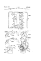
- FIGURE 1 shows a cathode ray tube in which a cathode assembly representing one embodiment of this invention has been mounted
- FIG. 2 shows an orthogonal view of one embodiment of this invention
- FIG. 3 shows a side view of the embodiment shown in FIG. 2;
- FIG. 4 shows a cathode assembly representing a second embodiment of this invention
- FIG. 5 shows a cathode assembly representing another embodiment of this invention
- FIG. 6 shows a still further embodiment of this invention.
- FIG. 7 shows another means for moving the flexible tape comprising another embodiment of this invention.
- FIG. 1 there is generally shown a cathode ray tube in which a cathode assembly 20 which comprises the essence of applicants invention is incorporated.
- the cathode ray tube comprises a glass envelope 10 in which there is mounted the cathode assembly Zil and the focusing and accelerating elements 12..
- the elements 12 are axially aligned with respect to the glass envelope 10 and in proximity to the cathode assembly 20 so as to focus and accelerate the electrons emitted from the cathode assembly 20 upon a target 16 at the other extremity of envelope 10.
- the cathode ray tube also has terminals 14 through which are supplied the necessary electrical signals for the cathode assembly 20 and the focusing and accelerating elements 12.
- FIGS. 2 and 3 show more specifically the structure of the cathode assembly 20.
- a continuous metallic tape or filamentary support 22 is disposed at its upper end about an exciting means or guide member 34 and at its lower end about a cylindrical pulley 24.
- the cylindrical pulley 24 is provided with a groove 26 into which the tape 22 fits.
- One portion of the cylindrical pulley 24 is provided with a plurality of ratchet teeth 28 through which is supplied the movement for turning the tape 22.
- An axial rod 29 about which the cylindrical pulley 24 may rotate.
- a dog member 27 is so positioned that one end thereof engages the ratchet teeth 28 of pulley 24.
- the upper portion of the tape 22 is suspended by guide member 34; the tape 22 is held in place by groove 33 in guide member 34.
- a beveled portion 36 is provided in guide member 34 over which a discrete portion 37 of the tape 22 rests.
- the means for exciting the guide member 34 includes a centrally aligned bore 35 within which is inserted a filament heater 38. The filament heater 3% serves to heat the guide member 34 and in turn, the discrete portion 37 of the tape 22.
- a tensioning spring 36 is located between the guide member 34 and the cylindrical pulley 24 to apply a constant tension to the tape 22.. As can be seen in FIG. 2, the tensioning spring Stl has a pair of biasing members 39 which rest against the flat portions of tape 22 thereby applying tension.
- the material of which the tape 22 is to be made is selected on the basis of its flexibility and also its resistance to high temperatures.
- a nickel, a molybdenum or a tungsten tape with a thickness in the order of .001 inch would be suitable for application in many types of electron devices.
- a layer of barium, calcium and strontium oxides commonly known as triple oxides may be placed on the tape to provide an emi-ssive source of electrons. Such a layer could be deposited upon the tape in a manner well known in the art such as spraying, or electrophoresis.
- an electron emissive layer could be omitted if the tape 22 is made of tungsten or a thoriated tungsten which metals could serve as the source of electrons.
- the cathode assembly 20 is contained within a grid cup 52.
- a support member 50 Centrally located within the grid cup 52 is a support member 50 which is secured to the enclosed end of the grid cup 52.
- On the sides of the support member 50 there are various holes for holding and positioning the elements of the cathode assembly 20.
- axial rod 29 is rigidly secured within holes 55; support flanges 31 of the tensioning spring 30 are secured against the sides of support member 50; guide member 34 is supported between sides of the support member 50 and holes 57 are provided to allow passage of the leads for the filament heater 38.
- the dog member 27 (shown in FIG. 2) has one end fixedly secured to the support member 50 and its other end engaging ratchet teeth 28.
- the guide member 34 is rigidly secured to the sides of the support member 50 so that the beveled portion 36 always faces the enclosed end of the grid cup 52.
- the means for causing the tape 22 to move with respect to the guide member 34 is provided by a bimetallic spiral 40, which is mounted on a tube 42.
- One end 46 of the bimetallic spiral 40 may be fastened to the tube 42 by any means known in the art such as welding.
- the extending end 47 of the spiral 40 projects upward and away from the tube and has a hook like engaging end 48.
- the engaging end 48 meshes with the ratchet teeth 28 of the cylindrical pulley 24.
- the tube 42 and the bimetallic spiral 40 are secured to the support member 50.
- the ends of tube 42 fit within holes 53 in each side of the support member 50.
- a spiral heater 44 is provided within a bore 45 of the tube 42 in order to heat and thus energize the bimetallic spiral 40.
- One metal of the bimetallic spiral 40 may be made of a low thermal expansion material such as Invar, while the other metal could be selected from those high thermal expansion materials such as brass, stainless steel (188) or silver.
- the discrete portion 37 lying on the beveled portion 36 of the guide members 34 and beneath the aperture 54 will deteriorate in time; that is to say, the electron emissive layer upon the tape 22 will have lost partially or totally its emissivity.
- the tape 22 may be rotated bringing a new portion of the tape 22 upon the beveled portion 36. Such rotation may be caused by the metallic spiral 40.
- the heater 44 is energized and the resultant heat will cause the bimetallic spiral 40 to spiral or flex so that the extending end 47 forces the engaging end 48 into and against the ratchet teeth 28 thereby rotating the cylindrical pulley 24 in a clockwise direction (as shown in FIG. 2).
- the cylindrical pulley 24 and consequently the tape 22 are rotated, thereby renewing the emissive layer beneath the aperture 54.
- the dog member 27 has been so positioned against the ratchet teeth 28 to prevent a reverse rotation in the counterclockwise direction. It is noted that the heater 44 can be eliminated and the bimetal 40 could be heated directly by a flow of current through its length produced by a potential difference applied across the ends of the bimetal 40. i
- FIG. 4 A second embodiment of applicants invention involving a directly heated cathode is shown in FIG. 4.
- a continuous metallic tape or filamentary support 22 with an electron emissive coating thereon is used to renew the portion of the tape 22 in the emitting position.
- the tape 22 is suspended from a means for exciting such as two electrically insulated guide electrodes 60, and a cylindrical pulley 24a.
- the electrodes 60 could be made of a metal such as molybdenum, tungsten, nickel or stainless steel.
- Grooves 62 in the guide electrodes 60 provide a channel through which the tape 22 may be drawn.
- a tension spring 30 is provided to hold the tape 22 under tension.
- a groove 26a in the cylindrical pulley 24a is provided to hold the tape 22 in place with respect to the pulley 24a. It is noted that the various elements as shown in FIG. 4 may be held in place in a manner similar to that shown in FIG. 3. In particular the guide electrodes 60 would be rigidly held against the sides of a member similar to support member 50. The axial rod 29 would likewise be rigidly secured to a support member.
- the electron emissive layer upon tape 22 is directly heated by a current applied through the tape 22.
- a suitable voltage of approximately 6.3 v. is applied across the guide electrodes 60 so that a current will flow through the portion 64 of the tape 22 lying across the electrodes 60.
- the resulting current flowing through tape 22 will heat the portion 64 which will, in turn, emit a stream of electrons.
- portion 64 would be positioned in a grid cup beneath the aperture similar to that shown in FIG. 3.
- the length of the portion 64 of the tape is made small in comparison with the remaining portion of the tape 22, so that the greater portion of the current flowing between guide electrodes 60 will flow through the emissive portion 64.
- One particular advantage of the embodiment shown in FIG. 4 is that the heating element, i.e., portion 64, will be renewed each time the tape 22 is moved.
- the cylindrical pulley 24a has been modified in this embodiment to receive a different form of motivation.
- Cylindrical pulley 24a has therein a concentric bore 78 upon the inner periphery of which there is placed a plurality of ratchet teeth 72.
- One end 74 of the bimetallic spiral 70 is mechanically secured to the axial rod 29, whereas another end 73 is so positioned as to engage the plurality of ratchet teeth 72.
- another plurality of ratchet teeth 82 Upon the other end of the cylindrical pulley 24a there is located another plurality of ratchet teeth 82.
- a dog member is provided to engage the matchet teeth 82.
- a suitable voltage such as 6.3 volts, is applied through brushes 75 between the axial rod 29 and the cylindrical pulley 24a. It is noted that there is provided proper insulation (not shown) between the axial rod 29, the cylindrical pulley 24a, and the spiral 70 so that the voltage so applied induces a current through the length of the bimetallic spiral 70 thereby heating it.
- the bimetallic spiral 70 When the bimetallic spiral 70 is heated it will be caused to flex or spiral outward thereby inducing a clockwise motion (as shown in FIG. 4) in the cylindrical pulley 24a and thereby causing the tape 22 to rotate to a new position.
- the action of the dog member 80 will prevent the cylindrical pulley 24a from being rotated in a counterclockwise direction (as shown in FIG. 4) when the spiral 70 cools. In this manner the emissive portion of the tape 22 lying across the electrodes 60 can be renewed.
- One advantage of those embodiments shown in FIGS. 2, 3 and 4 is that only the portion of the tape 22 emitting electrons into the aperture 54 is heated to the operating temperature which is in the order of 1l00 K. Such portions may be identified as portions 64 and 37 in FIGS. 4 and 2 respectively. The remaining, longer portions of the tape 22 are subjected to considerably lower temperatures whereby the emissive area upon tape 22 may be preserved. In particular, in the case of an oxide cathode the evaporation of the oxides forming the emissive layer and the formatron of an interface layer are prevented. In practice various reducing elements such as silicon, magnesium, Wolfram and silicon are introduced into the metal of wh ch the support 22 is made to promote the cathode act1vity.
- various reducing elements such as silicon, magnesium, Wolfram and silicon are introduced into the metal of wh ch the support 22 is made to promote the cathode act1vity.
- the triple oxides forming the emissive coating may react with those reducing elements forming the interface layer.
- the interface layer may cause excessive voltage drop across the emissive layer resulting in the possible overheating of the emissive layer. Therefore, by keeping the remaining portions of the tape 22 at a reduced temperature, the evaporation of the oxides and the formation of an interface layer are substantially retarded.
- FIGS. 5 and 6 two embodiments of applicants invention are shown involving a non-continuous tape filamentary support 22b.
- a magazine St is provided with a given length of metallic tape 22b either bare or provided with an emissive coating thereon.
- the tape 22! is brought from magazine 80 to a take-up magazine 81 where the used portions of the tape 22b may be wound.
- a bimetallic motivating means is provided for rotating the take-up magazine 81.
- the motivating means comprises a bimetallic element 88 and a heater element 90 for motivating said bimetallic element 88.
- a directly heated cathode is shown wherein the tape 22b is drawn across a means for exciting such as electrodes 84.
- a voltage source 82 is applied between the electrodes 84 with a resultant current flowing through a portion 96 of the tape 2% in the emitting position.
- a means for exciting comprising a hollow cathode sleeve 92 which is placed against an emissive portion 98 of the tape 22b.
- heater elements 97 which when energized will heat the cathode sleeve 92 and, in turn, the emissive portion 98 thereby producing an electron stream.
- the heater element 90 will be energized thereby flexing bimetallic element 88.
- the bimetallic element 88 engages a ratchet Wheel 86.
- the ratchet wheel 86 will rotate thereby causing the tape 22b to move across onto the take-up magazine 81 and to renew the emissive portions of the tape 22b in contact with the cathode sleeve 92.
- FIG. 7 there is shown another system for motivating a filamentary support or flexible metallic tape 22c past a pair of electrodes 1692.
- a plurality of ratchet teeth 120 are provided on one edge of the metallic tape 22c
- a bimetallic member 124 is so positioned that its engaging portion 125 meshes with the ratchet teeth 125).
- a heating element 126 is thermally positioned about the bimetallic member 124. It is noted that the heating element 126 may be eliminated and the bimetallic member 124 may be heated directly by current being passed through its length.
- a voltage source 128 is connected with a switch 130 in such a manner that voltage may be selectively impressed either across the pair of electrodes 102 or across the heating element 126.
- cathode ray tubes In some types of cathode ray tubes the cathode areas required are quite small. Consequently, even relatively short tapes or wires may provide many cathode and heater renewals if desired.
- the cathode emissive area or portion may be renewed a large number of times by relatively inexpensive means.
- the bimetallic member can be easily mounted within the envelope of the cathode ray tube with the result that the more complex and expensive inductive motor means may be eliminated.
- the emissive portion of the 6 cathode may be repeatedly renewed a great many times.
- the tube life as dependent upon the condition of the cathode emissive surface is only limited by the amount of tape that can be stored within the magazines or may be placed on a continuous tape belt.
- An electron discharge device comprising an elongated, flexible filamentary support having at least first and second emissive portions for producing an electron beam, a target means for receiving said beam, means for exciting electrons in association with said first emissive portion, magazine means for storing an extended ength of said filamentary support in a contracted configuration, and means for moving said support so that said second emissive portion is brought into association with said means for exciting and said first emissive portion is displaced from said means for exciting.
- An electron discharge device comprising a flexible tape having at least first and second emissive portions for producing an electron beam, a target means for receiving said beam, means for exciting electrons in association with said first emissive portion, means for storing an extended length of said flexible tape in a contracted configuration, and means for moving said tape support so that said second emissive portion is brought into association with said means for exciting electrons and said first portion is displaced from said means for exciting electrons.
- An electron discharge device comprising a flexible tape support having at least first and second emissive portions for producing an electron beam, a target means for receiving said beam, two electrodes with a means for applying a potential thereacross, said flexible support so placed across said electrodes that an electrical current passes through said first emissive portion, and means for linearly moving said flexible support so that said second emissive portion is placed between said electrodes and said first portion is displaced.
- An electron discharge device comprising an elongated, flexible filamentary support having a plurality of emissive portions for producing an electron beam, a target means for receiving said beam, a means for guiding said filamentary support including a means for heating in thermal association with one of said emissive portions, means for storing an extended length of said flexible support in a contracted configuration, and means for moving said elongated filamentary support along the elongated dimension of said filamentary support so that another of said emissive portion is placed in association with said means for guiding and said one portion is displaced therefrom.
- An electron discharge device comprising a flexible tape support having at least first and second emissive portions for producing an electron beam, a target means for receiving said beam, means for exciting electrons in association with said first emissive portion, means for storing an extended length of said flexible tape support in a contracted configuration, and means for moving said tape support along the longitudinal axis of said tape support so that said second emissive portion is placed in association with said means for exciting and said first portion is displaced.
- An electron discharge device as claimed in claim 5, wherein the means for exciting comprises a guide member and a means for heating in thermal association with said tape support.
- An electron discharge device comprising a continuous flexible tape having an electron emissive coating for producing an electron beam, said flexible tape having first and second portions, a target means for receiving said beam, two electrodes spaced apart, said first portion being disposed between said electrodes, said second portion being of a greater length than said first portion, and means for moving said continuous flexible tape past said electrodes.
- a cathode assembly comprising a flexible filamentary support having at least first and second emissive portions for producing an electron beam, a means for exciting electrons in association with said first emissive portion, means for storing an extended length of said filamentary support in a contracted configuration, and means for linearly moving said support so that said second emissive portion is in association with said means for exciting electrons and so that said first emissive portion is removed therefrom.
- An electron discharge device comprising an envelope, a flexible tape having a coating of emissive ma terial for producing an electron beam, said coating supported by said flexible tape having at least first and second emissive portions, a target means for receiving said electron beam, a means for exciting electrons in association with said first emissive portion, means for storing an extended length of said flexible tape in a contracted configuration, and means within said envelope for moving said tape across said means for exciting so that said second emissive portion is disposed in association wtih said means for exciting electrons and said first emissive portion is displaced therefrom.
- An electron discharge device as claimed in claim 9 wherein said means for moving comprises a thermal responsive bimetal member engaging a plurality of teeth in said flexible tape, and a heating means for activating said bimetal member.
- An electron discharge device as claimed in claim 9 wherein said means for moving includes tWo magazines, one for dispensing and the other for collecting said fiexible tape, one of said magazines having a sprocket member with a plurality of teeth therein, a thermal responsive bimetal member engaging said plurality of teeth and a heating means for activating said bimetal member.
- An electron discharge device comprising a filamentary belt support having a plurality of emissive portions for producing an electron beam, a target means for receiving said beam, a means for exciting electrons in association with one of said emissive portions, and a means for moving said belt including a pulley means having a plurality of teeth therein, a thermal-responsive element in engagement with said plurality of teeth, and a heating means in association with said thermal-responsive element.
- An electron discharge device comprising a continuous filamentary belt having a plurality of emissive portions for producing an electron beam, a target means for receiving said electron beam, a guide member for supporting said belt including therein a first heating element, a means for motivating said belt including a rotatably mounted pulley with a plurality of ratchet teeth about its periphery, a biasing member for applying tension to said belt, and a means for motivating said pulley including a thermal-responsive bimetal element having one end securedly fixed and its other end in engagement with said plurality of teeth and a second heating element for energizing said bimetal element.
- An electron discharge device comprising a continuous filamentary belt having a plurality of emissive portions for producing an electron beam, a target means for receiving said beam, two electrodes spaced a given distance apart, said belt passing over said two electrodes, a means for motivating said belt including a pulley having a first and second portion, said means for motivating being mounted on an axial rod, a spinaled bimetal element having one end thereof fixedly secured to said axial rod, and a detent means for preventing said pulley from rotating backwards, said first portion of said pulley having a bore therein with a plurality of first ratchet teeth on the periphery of said bore, the other end of said spiraled bimetal element engaging said plurality of first ratchet teeth, said second portion of said pulley having a plurality of second ratchet teeth, said detent means being in engagement wtih said plurality of second ratchet teeth, and a biasing member for applying a tension to said belt.
- a cathode assembly comprising a flexible filamentary support having at least first and second emissive portions for producing an electron beam, a means for exciting electrons in association with said first emissive portion, means for storing an extended length of said flexible, filamentary support in a contracted configuration, and means for linearly moving said support across said means for exciting electrons and so that said first emissive portion is removed therefrom, said means for moving including a conductive, thermally responsive element.
Landscapes
- Microwave Tubes (AREA)
Description
Dec. 6, 1966 ATT] 3,290,540
ELECTRON DISCHARGE TUBE HAVING A MOVABLE CATHODE TAPE Filed April 16, 1964 2 Sheets-Sheet 1 INVENTOR WITNESSES Eros Afli JQIMJWM '3 @aw 7.414 I fig fK E. ATTl Dec. 6, 1966 ELECTRON DISCHARGE TUBE HAVING A MOVABLE CATHODE TAPE 2 Sheets-Sheet 2 Filed April 16, 1964 4O BIMETAL Fig.4.
COATING L EMISSIVE United States Patent 3,290,540 ELECTRON DISCHARGE TUBE HAVING A MUVABLE CATHODE TAPE Eros Atti, Horseheads, N.Y., assignor to Westinghouse Electric Corporation, East Pittsburgh, Pa., a corporation of Pennsylvania Filed Apr. 16, 1964, Ser. No. 360,268 Claims. (Cl. 313146) This invention relates in general to electron discharge devices and more particularly to means for renewing the emissive surface of the cathode elements of electron tubes.
In the use of electronic tubes of certain types, the problem exists that after a relatively few hours of operation the drawing of current from the cathode element tends to dissipate the emissive surface of the cathode element. The deterioration of the cathode element is aggravated when the cathode element is subjected to heavy current drains or is operated in an unfavorable environmental condition such as a poor vacuum. The surface of the emissive cathode element tends to become poisoned and at times pitted so that the electron emission of this element tends to become irregular. As a solution for the problem of cathode deterioration it has been suggested that the emissive portion of the cathode element may be renewed by rotating the cathode element about an axis thereby using an annular portion of the cathode element. In order to so motivate the cathode a complicated motor induction assembly has been suggested, which requires a complex means for inducing the driving field necessarily mounted exteriorly of the tube envelope. One obvious limitation of this solution is the complexity of the additional apparatus required and also the additional mounting required for the induction coils and members on the exterior of the tube. Further, the life expectancy of the cathode element is limited by the usable area available on a single disc cathode element.
Further, another simplified means for renewing the emissive portion of a cathode using a movable cathode disc is disclosed in a copending application Serial No. 353,683 to Eros Atti and assigned to the assignee of this inventon.
Accordingly, it is the general object of this invention to provide a new and improved electron device.
More specifically, it is the object of this invention to provide an electron device having a cathode assembly with a plurality of emissive portions which may be re peatedly changed a great number of times thereby greatly prolonging the useful life of the electronic device.
It is a still more particular object of this invention to provide an electron tube having a cathode assembly with a plurality of emissive portions which may be repeatedly changed a great number of times by simple and inexpensive driving means.
Briefly, the present invention accomplishes the above cited objects by providing a cathode assembly utilizing a filamentary support, such as a flexible tape, which is itself or has a coating thereon capable of emitting electrons. Means are provided for advancing the flexible support so that as one portion of the emissive area becomes ineifective or deteriorated the support can be drawn away from the emitting position and be replaced by a different portion of the filamentary support. In accordance with the invention, the tape is stored Within the tube envelope and is advanced through a ratchet and pawl arrangement within the tube responsive to the application of potential to a pair of external tube terminals. For the purpose of electron emission, the tape may be heated externally or may be heated by current passed through the conductive portion thereof in the emitting position.
Further objects and advantages of the invention will become apparent as the following description proceeds lCC and features of novelty which characterize the invention will be pointed out in particularity in the claims annexed to and which form a part of this specification.
For a better understanding of the invention, reference may be had to the accompanying drawings, in which:
FIGURE 1 shows a cathode ray tube in which a cathode assembly representing one embodiment of this invention has been mounted;
FIG. 2 shows an orthogonal view of one embodiment of this invention;
FIG. 3 shows a side view of the embodiment shown in FIG. 2;
FIG. 4 shows a cathode assembly representing a second embodiment of this invention;
FIG. 5 shows a cathode assembly representing another embodiment of this invention;
FIG. 6 shows a still further embodiment of this invention; and
FIG. 7 shows another means for moving the flexible tape comprising another embodiment of this invention.
In FIG. 1 there is generally shown a cathode ray tube in which a cathode assembly 20 which comprises the essence of applicants invention is incorporated. The cathode ray tube comprises a glass envelope 10 in which there is mounted the cathode assembly Zil and the focusing and accelerating elements 12.. The elements 12 are axially aligned with respect to the glass envelope 10 and in proximity to the cathode assembly 20 so as to focus and accelerate the electrons emitted from the cathode assembly 20 upon a target 16 at the other extremity of envelope 10. The cathode ray tube also has terminals 14 through which are supplied the necessary electrical signals for the cathode assembly 20 and the focusing and accelerating elements 12.
FIGS. 2 and 3 show more specifically the structure of the cathode assembly 20. A continuous metallic tape or filamentary support 22 is disposed at its upper end about an exciting means or guide member 34 and at its lower end about a cylindrical pulley 24. The cylindrical pulley 24 is provided with a groove 26 into which the tape 22 fits. One portion of the cylindrical pulley 24 is provided with a plurality of ratchet teeth 28 through which is supplied the movement for turning the tape 22. Through the center of cylindrical pulley 24 there is aligned an axial rod 29 about which the cylindrical pulley 24 may rotate. A dog member 27 is so positioned that one end thereof engages the ratchet teeth 28 of pulley 24. The upper portion of the tape 22 is suspended by guide member 34; the tape 22 is held in place by groove 33 in guide member 34. A beveled portion 36 is provided in guide member 34 over which a discrete portion 37 of the tape 22 rests. The means for exciting the guide member 34 includes a centrally aligned bore 35 within which is inserted a filament heater 38. The filament heater 3% serves to heat the guide member 34 and in turn, the discrete portion 37 of the tape 22. A tensioning spring 36 is located between the guide member 34 and the cylindrical pulley 24 to apply a constant tension to the tape 22.. As can be seen in FIG. 2, the tensioning spring Stl has a pair of biasing members 39 which rest against the flat portions of tape 22 thereby applying tension.
The material of which the tape 22 is to be made is selected on the basis of its flexibility and also its resistance to high temperatures. A nickel, a molybdenum or a tungsten tape with a thickness in the order of .001 inch would be suitable for application in many types of electron devices. Further, a layer of barium, calcium and strontium oxides commonly known as triple oxides may be placed on the tape to provide an emi-ssive source of electrons. Such a layer could be deposited upon the tape in a manner well known in the art such as spraying, or electrophoresis. In addition, an electron emissive layer could be omitted if the tape 22 is made of tungsten or a thoriated tungsten which metals could serve as the source of electrons.
As more clearly shown in FIG. 3, the cathode assembly 20 is contained within a grid cup 52. Centrally located within the grid cup 52 is a support member 50 which is secured to the enclosed end of the grid cup 52. On the sides of the support member 50, there are various holes for holding and positioning the elements of the cathode assembly 20. In particular, axial rod 29 is rigidly secured within holes 55; support flanges 31 of the tensioning spring 30 are secured against the sides of support member 50; guide member 34 is supported between sides of the support member 50 and holes 57 are provided to allow passage of the leads for the filament heater 38. The dog member 27 (shown in FIG. 2) has one end fixedly secured to the support member 50 and its other end engaging ratchet teeth 28. It is noted that the guide member 34 is rigidly secured to the sides of the support member 50 so that the beveled portion 36 always faces the enclosed end of the grid cup 52. An aperture 54 through which fiows the electron beam is oentrally located in the enclosed end of the grid cup 52; the support member 50 is positioned within the grid cup 52 so that the discrete portion 37 of the tape 22 is positioned just beneath the aperture 54.
In the illustrated embodiment of the invention, the means for causing the tape 22 to move with respect to the guide member 34 is provided by a bimetallic spiral 40, which is mounted on a tube 42. One end 46 of the bimetallic spiral 40 may be fastened to the tube 42 by any means known in the art such as welding. The extending end 47 of the spiral 40 projects upward and away from the tube and has a hook like engaging end 48. The engaging end 48 meshes with the ratchet teeth 28 of the cylindrical pulley 24. The tube 42 and the bimetallic spiral 40 are secured to the support member 50. The ends of tube 42 fit within holes 53 in each side of the support member 50. A spiral heater 44, the leads of which are shown in the drawings 2 and 3, is provided within a bore 45 of the tube 42 in order to heat and thus energize the bimetallic spiral 40. One metal of the bimetallic spiral 40 may be made of a low thermal expansion material such as Invar, while the other metal could be selected from those high thermal expansion materials such as brass, stainless steel (188) or silver.
During the course of operation of this electron device, the discrete portion 37 lying on the beveled portion 36 of the guide members 34 and beneath the aperture 54 will deteriorate in time; that is to say, the electron emissive layer upon the tape 22 will have lost partially or totally its emissivity. In order to renew the emissive layer upon portion 37, the tape 22 may be rotated bringing a new portion of the tape 22 upon the beveled portion 36. Such rotation may be caused by the metallic spiral 40. In order to activate the bimetallic spiral 40, the heater 44 is energized and the resultant heat will cause the bimetallic spiral 40 to spiral or flex so that the extending end 47 forces the engaging end 48 into and against the ratchet teeth 28 thereby rotating the cylindrical pulley 24 in a clockwise direction (as shown in FIG. 2). As a result of the flexing motion of the spiral 40 the cylindrical pulley 24 and consequently the tape 22 are rotated, thereby renewing the emissive layer beneath the aperture 54. When the bimetal 40 is cooled, there would be a tendency for the engaging end 48 to rotate the pulley 24 in a counterclockwise direction (as shown in FIG. 2). The dog member 27 has been so positioned against the ratchet teeth 28 to prevent a reverse rotation in the counterclockwise direction. It is noted that the heater 44 can be eliminated and the bimetal 40 could be heated directly by a flow of current through its length produced by a potential difference applied across the ends of the bimetal 40. i
A second embodiment of applicants invention involving a directly heated cathode is shown in FIG. 4. As in FIGS. 2 and 3, a continuous metallic tape or filamentary support 22 with an electron emissive coating thereon is used to renew the portion of the tape 22 in the emitting position. The tape 22 is suspended from a means for exciting such as two electrically insulated guide electrodes 60, and a cylindrical pulley 24a. The electrodes 60 could be made of a metal such as molybdenum, tungsten, nickel or stainless steel. Grooves 62 in the guide electrodes 60 provide a channel through which the tape 22 may be drawn. A tension spring 30 is provided to hold the tape 22 under tension. A groove 26a in the cylindrical pulley 24a is provided to hold the tape 22 in place with respect to the pulley 24a. It is noted that the various elements as shown in FIG. 4 may be held in place in a manner similar to that shown in FIG. 3. In particular the guide electrodes 60 would be rigidly held against the sides of a member similar to support member 50. The axial rod 29 would likewise be rigidly secured to a support member.
The electron emissive layer upon tape 22 is directly heated by a current applied through the tape 22. In order to accomplish this result, a suitable voltage of approximately 6.3 v. is applied across the guide electrodes 60 so that a current will flow through the portion 64 of the tape 22 lying across the electrodes 60. The resulting current flowing through tape 22 will heat the portion 64 which will, in turn, emit a stream of electrons. It is further noted that portion 64 would be positioned in a grid cup beneath the aperture similar to that shown in FIG. 3. The length of the portion 64 of the tape is made small in comparison with the remaining portion of the tape 22, so that the greater portion of the current flowing between guide electrodes 60 will flow through the emissive portion 64. One particular advantage of the embodiment shown in FIG. 4 is that the heating element, i.e., portion 64, will be renewed each time the tape 22 is moved.
The cylindrical pulley 24a has been modified in this embodiment to receive a different form of motivation. Cylindrical pulley 24a has therein a concentric bore 78 upon the inner periphery of which there is placed a plurality of ratchet teeth 72. Within the bore 78 and upon axial rod 29 there is secured a bimetallic spiral 70. One end 74 of the bimetallic spiral 70 is mechanically secured to the axial rod 29, whereas another end 73 is so positioned as to engage the plurality of ratchet teeth 72. Upon the other end of the cylindrical pulley 24a there is located another plurality of ratchet teeth 82. A dog member is provided to engage the matchet teeth 82.
In order to rotate the cylindrical pulley 24a and thereby the tape 22 a suitable voltage, such as 6.3 volts, is applied through brushes 75 between the axial rod 29 and the cylindrical pulley 24a. It is noted that there is provided proper insulation (not shown) between the axial rod 29, the cylindrical pulley 24a, and the spiral 70 so that the voltage so applied induces a current through the length of the bimetallic spiral 70 thereby heating it. When the bimetallic spiral 70 is heated it will be caused to flex or spiral outward thereby inducing a clockwise motion (as shown in FIG. 4) in the cylindrical pulley 24a and thereby causing the tape 22 to rotate to a new position. The action of the dog member 80 will prevent the cylindrical pulley 24a from being rotated in a counterclockwise direction (as shown in FIG. 4) when the spiral 70 cools. In this manner the emissive portion of the tape 22 lying across the electrodes 60 can be renewed.
One advantage of those embodiments shown in FIGS. 2, 3 and 4 is that only the portion of the tape 22 emitting electrons into the aperture 54 is heated to the operating temperature which is in the order of 1l00 K. Such portions may be identified as portions 64 and 37 in FIGS. 4 and 2 respectively. The remaining, longer portions of the tape 22 are subjected to considerably lower temperatures whereby the emissive area upon tape 22 may be preserved. In particular, in the case of an oxide cathode the evaporation of the oxides forming the emissive layer and the formatron of an interface layer are prevented. In practice various reducing elements such as silicon, magnesium, Wolfram and silicon are introduced into the metal of wh ch the support 22 is made to promote the cathode act1vity. However, at the more elevated temperatures the triple oxides forming the emissive coating may react with those reducing elements forming the interface layer. The interface layer may cause excessive voltage drop across the emissive layer resulting in the possible overheating of the emissive layer. Therefore, by keeping the remaining portions of the tape 22 at a reduced temperature, the evaporation of the oxides and the formation of an interface layer are substantially retarded.
In FIGS. 5 and 6, two embodiments of applicants invention are shown involving a non-continuous tape filamentary support 22b. Generally, a magazine St) is provided with a given length of metallic tape 22b either bare or provided with an emissive coating thereon. The tape 22!; is brought from magazine 80 to a take-up magazine 81 where the used portions of the tape 22b may be wound. A bimetallic motivating means is provided for rotating the take-up magazine 81. The motivating means comprises a bimetallic element 88 and a heater element 90 for motivating said bimetallic element 88. In the particular embodiment shown in FIG. 5, a directly heated cathode is shown wherein the tape 22b is drawn across a means for exciting such as electrodes 84. A voltage source 82 is applied between the electrodes 84 with a resultant current flowing through a portion 96 of the tape 2% in the emitting position. In FIG. 6 there is shown a means for exciting comprising a hollow cathode sleeve 92 which is placed against an emissive portion 98 of the tape 22b. Within the hollow cathode sleeve 92 there is placed heater elements 97 which when energized will heat the cathode sleeve 92 and, in turn, the emissive portion 98 thereby producing an electron stream. When it is desired to renew the portion of the cathode assemblies in the emitting position of either FIGS. 5 or 6, the heater element 90 will be energized thereby flexing bimetallic element 88. The bimetallic element 88 engages a ratchet Wheel 86. The ratchet wheel 86 will rotate thereby causing the tape 22b to move across onto the take-up magazine 81 and to renew the emissive portions of the tape 22b in contact with the cathode sleeve 92.
In FIG. 7, there is shown another system for motivating a filamentary support or flexible metallic tape 22c past a pair of electrodes 1692. A plurality of ratchet teeth 120 are provided on one edge of the metallic tape 22c A bimetallic member 124 is so positioned that its engaging portion 125 meshes with the ratchet teeth 125). A heating element 126 is thermally positioned about the bimetallic member 124. It is noted that the heating element 126 may be eliminated and the bimetallic member 124 may be heated directly by current being passed through its length. A voltage source 128 is connected with a switch 130 in such a manner that voltage may be selectively impressed either across the pair of electrodes 102 or across the heating element 126. When the switch 130 is in postiion Sll, voltage will be impressed across electrodes 102 with the result that a current will flow through a portion 132 of the tape 22c heating it to the proper operating temperature for electron emission; on the other hand, when the switch 130 is in position S2, the voltage source 128 will be impressed across the heating element 126 with the result that the bimetallic member 124 will force the tape 22c forward thereby renewing the portion 132 disposed across electrodes M2.
In some types of cathode ray tubes the cathode areas required are quite small. Consequently, even relatively short tapes or wires may provide many cathode and heater renewals if desired.
It should now be apparent that by using a relatively inexpensive bimetal member the cathode emissive area or portion may be renewed a large number of times by relatively inexpensive means. Further, the bimetallic member can be easily mounted within the envelope of the cathode ray tube with the result that the more complex and expensive inductive motor means may be eliminated. In addition, by using a spool or magazine of flexible tape or a continuous tape, the emissive portion of the 6 cathode may be repeatedly renewed a great many times. In fact the tube life as dependent upon the condition of the cathode emissive surface is only limited by the amount of tape that can be stored within the magazines or may be placed on a continuous tape belt.
While there have been shown and described what are presently considered to be the preferred embodiments of the invention, modifications thereto will readily occur to those skilled in the art. It is not desired, therefore, that the invention be limited to these specific arrangements or embodiments shown and described and it is intended to cover in the dependent claims all such modifications as fall within the true spirit and scope of the invention.
I claim as my invention:
1. An electron discharge device comprising an elongated, flexible filamentary support having at least first and second emissive portions for producing an electron beam, a target means for receiving said beam, means for exciting electrons in association with said first emissive portion, magazine means for storing an extended ength of said filamentary support in a contracted configuration, and means for moving said support so that said second emissive portion is brought into association with said means for exciting and said first emissive portion is displaced from said means for exciting.
2. An electron discharge device comprising a flexible tape having at least first and second emissive portions for producing an electron beam, a target means for receiving said beam, means for exciting electrons in association with said first emissive portion, means for storing an extended length of said flexible tape in a contracted configuration, and means for moving said tape support so that said second emissive portion is brought into association with said means for exciting electrons and said first portion is displaced from said means for exciting electrons.
3. An electron discharge device comprising a flexible tape support having at least first and second emissive portions for producing an electron beam, a target means for receiving said beam, two electrodes with a means for applying a potential thereacross, said flexible support so placed across said electrodes that an electrical current passes through said first emissive portion, and means for linearly moving said flexible support so that said second emissive portion is placed between said electrodes and said first portion is displaced.
4. An electron discharge device comprising an elongated, flexible filamentary support having a plurality of emissive portions for producing an electron beam, a target means for receiving said beam, a means for guiding said filamentary support including a means for heating in thermal association with one of said emissive portions, means for storing an extended length of said flexible support in a contracted configuration, and means for moving said elongated filamentary support along the elongated dimension of said filamentary support so that another of said emissive portion is placed in association with said means for guiding and said one portion is displaced therefrom.
5. An electron discharge device comprising a flexible tape support having at least first and second emissive portions for producing an electron beam, a target means for receiving said beam, means for exciting electrons in association with said first emissive portion, means for storing an extended length of said flexible tape support in a contracted configuration, and means for moving said tape support along the longitudinal axis of said tape support so that said second emissive portion is placed in association with said means for exciting and said first portion is displaced.
6. An electron discharge device, as claimed in claim 5, wherein the means for exciting comprises a guide member and a means for heating in thermal association with said tape support.
7. An electron discharge device comprising a continuous flexible tape having an electron emissive coating for producing an electron beam, said flexible tape having first and second portions, a target means for receiving said beam, two electrodes spaced apart, said first portion being disposed between said electrodes, said second portion being of a greater length than said first portion, and means for moving said continuous flexible tape past said electrodes.
8. A cathode assembly comprising a flexible filamentary support having at least first and second emissive portions for producing an electron beam, a means for exciting electrons in association with said first emissive portion, means for storing an extended length of said filamentary support in a contracted configuration, and means for linearly moving said support so that said second emissive portion is in association with said means for exciting electrons and so that said first emissive portion is removed therefrom.
9. An electron discharge device comprising an envelope, a flexible tape having a coating of emissive ma terial for producing an electron beam, said coating supported by said flexible tape having at least first and second emissive portions, a target means for receiving said electron beam, a means for exciting electrons in association with said first emissive portion, means for storing an extended length of said flexible tape in a contracted configuration, and means within said envelope for moving said tape across said means for exciting so that said second emissive portion is disposed in association wtih said means for exciting electrons and said first emissive portion is displaced therefrom.
10. An electron discharge device as claimed in claim 9 wherein said means for moving comprises a thermal responsive bimetal member engaging a plurality of teeth in said flexible tape, and a heating means for activating said bimetal member.
11. An electron discharge device as claimed in claim 9 wherein said means for moving includes tWo magazines, one for dispensing and the other for collecting said fiexible tape, one of said magazines having a sprocket member with a plurality of teeth therein, a thermal responsive bimetal member engaging said plurality of teeth and a heating means for activating said bimetal member.
12. An electron discharge device comprising a filamentary belt support having a plurality of emissive portions for producing an electron beam, a target means for receiving said beam, a means for exciting electrons in association with one of said emissive portions, and a means for moving said belt including a pulley means having a plurality of teeth therein, a thermal-responsive element in engagement with said plurality of teeth, and a heating means in association with said thermal-responsive element.
13. An electron discharge device comprising a continuous filamentary belt having a plurality of emissive portions for producing an electron beam, a target means for receiving said electron beam, a guide member for supporting said belt including therein a first heating element, a means for motivating said belt including a rotatably mounted pulley with a plurality of ratchet teeth about its periphery, a biasing member for applying tension to said belt, and a means for motivating said pulley including a thermal-responsive bimetal element having one end securedly fixed and its other end in engagement with said plurality of teeth and a second heating element for energizing said bimetal element.
14. An electron discharge device comprising a continuous filamentary belt having a plurality of emissive portions for producing an electron beam, a target means for receiving said beam, two electrodes spaced a given distance apart, said belt passing over said two electrodes, a means for motivating said belt including a pulley having a first and second portion, said means for motivating being mounted on an axial rod, a spinaled bimetal element having one end thereof fixedly secured to said axial rod, and a detent means for preventing said pulley from rotating backwards, said first portion of said pulley having a bore therein with a plurality of first ratchet teeth on the periphery of said bore, the other end of said spiraled bimetal element engaging said plurality of first ratchet teeth, said second portion of said pulley having a plurality of second ratchet teeth, said detent means being in engagement wtih said plurality of second ratchet teeth, and a biasing member for applying a tension to said belt.
15. A cathode assembly comprising a flexible filamentary support having at least first and second emissive portions for producing an electron beam, a means for exciting electrons in association with said first emissive portion, means for storing an extended length of said flexible, filamentary support in a contracted configuration, and means for linearly moving said support across said means for exciting electrons and so that said first emissive portion is removed therefrom, said means for moving including a conductive, thermally responsive element.
References Cited by the Examiner UNITED STATES PATENTS 254,032 2/1882 Maxim 313-341 339,253 4/1886 Arnold 315 1,523,362 1/1925 Shedd 31565 1,812,103 6/1931 MacRae 117223 1,826,011 10/1931 McCullough 117233 X 2,405,789 8/1946 Homrighous 315-65 2,825,838 3/1958 Charles 313-337 X 3,197,665 7/ 1965 Cope 3l3270 X FOREIGN PATENTS 1,217,166 12/1959 France.
886,636 8/1953 Germany.
479,270 2/1938 Great Britain.
663,730 12/ 1951 Great Britain.
751,818 7/ 1956 Great Britain.
References Cited by the Applicant UNITED STATES PATENTS 2,175,582 10/1939 Vogel et a1. 3,009,762 7/ 1963 Hertz. 3,109,953 11/1963 Barnett.
JOHN W. HUCKERT, Primary Examiner.
A. J. JAMES, Assistant Examiner.
Claims (1)
1. AN ELECTRON DISCHARGE DEVICE COMPRISING AN ELONGATED FLEXIBLE FILAMENTARY SUPPORT HAVING AT LEAST FIRST AND SECOND EMISSIVE PORTIONS FOR PRODUCING AN ELECTRON BEAM, A TARGET MEANS FOR RECEIVING SAID BEAM, MEANS FOR EXCITING ELECTRONS IN ASSOCIATION WITH SAID FIRST EMISSIVE PORTION, MAGAZINE MEANS FOR STORING AN EXTENDED LENGTH OF SAID FILAMENTARY SUPPORT N A CONTRACTED CONFIGURATION, AND MEANS FOR MOVING SAID SUPPORT SO THAT SAID SECOND EMISSIVE PORTION IS BROUGH INTO ASSOCIATION WITH SAID MEANS FOR EXCITING AND SAID FIRST EMISSIVE PORTION IS DISPLACED FROM SAID MEANS FOR EXCITING.
Priority Applications (1)
| Application Number | Priority Date | Filing Date | Title |
|---|---|---|---|
| US360268A US3290540A (en) | 1964-04-16 | 1964-04-16 | Electron discharge tube having a movable cathode tape |
Applications Claiming Priority (1)
| Application Number | Priority Date | Filing Date | Title |
|---|---|---|---|
| US360268A US3290540A (en) | 1964-04-16 | 1964-04-16 | Electron discharge tube having a movable cathode tape |
Publications (1)
| Publication Number | Publication Date |
|---|---|
| US3290540A true US3290540A (en) | 1966-12-06 |
Family
ID=23417278
Family Applications (1)
| Application Number | Title | Priority Date | Filing Date |
|---|---|---|---|
| US360268A Expired - Lifetime US3290540A (en) | 1964-04-16 | 1964-04-16 | Electron discharge tube having a movable cathode tape |
Country Status (1)
| Country | Link |
|---|---|
| US (1) | US3290540A (en) |
Cited By (8)
| Publication number | Priority date | Publication date | Assignee | Title |
|---|---|---|---|---|
| US4080546A (en) * | 1974-10-16 | 1978-03-21 | Steigerwald Strahltechnik Gmbh | Beam splitter for electron beam machines |
| US4281269A (en) * | 1977-04-27 | 1981-07-28 | Ledley Robert S | Microfocus X-ray tube |
| US4344013A (en) * | 1979-10-23 | 1982-08-10 | Ledley Robert S | Microfocus X-ray tube |
| EP0063190A1 (en) * | 1981-04-21 | 1982-10-27 | LEDLEY, Robert S. | Microfocus X-ray tube |
| WO1982004350A1 (en) * | 1981-05-26 | 1982-12-09 | Aircraft Co Hughes | Filament dispenser cathode |
| EP0129942A1 (en) * | 1983-06-28 | 1985-01-02 | Koninklijke Philips Electronics N.V. | Electron beam apparatus comprising a wire source |
| US4734586A (en) * | 1986-03-06 | 1988-03-29 | The United States Of America As Represented By The United States Department Of Energy | Foil changing apparatus |
| US20140029730A1 (en) * | 2012-07-26 | 2014-01-30 | Agilent Technologies, Inc. | Tensioned flat electron emitter tape |
Citations (15)
| Publication number | Priority date | Publication date | Assignee | Title |
|---|---|---|---|---|
| US254032A (en) * | 1882-02-21 | Hiram s | ||
| US339253A (en) * | 1886-04-06 | aexold | ||
| US1523362A (en) * | 1918-11-13 | 1925-01-13 | Adolphe Danziger | Incandescent electric lamp |
| US1812103A (en) * | 1922-09-11 | 1931-06-30 | Westinghouse Lamp Co | Electron emitting device and method of making |
| US1826011A (en) * | 1923-09-17 | 1931-10-06 | Frederick S Mccullough | Electron emitting cathode and method of forming same |
| GB479270A (en) * | 1935-11-15 | 1938-02-02 | Cfcmug | Improvements in or relating to cathode ray tubes |
| US2405789A (en) * | 1942-08-22 | 1946-08-13 | John H Homrighous | Multifilament lamp |
| GB663730A (en) * | 1947-11-05 | 1951-12-27 | Hans Pius Barasch | Improvements in or relating to electron discharge devices |
| DE886636C (en) * | 1937-02-16 | 1953-08-17 | Lorenz C Ag | Arrangement for beam generation in glow cathode tubes, preferably for Braun tubes for television purposes |
| GB751818A (en) * | 1953-06-04 | 1956-07-04 | Csf | Improvements in electron sources |
| US2825838A (en) * | 1953-06-04 | 1958-03-04 | Csf | Electron sources |
| FR1217166A (en) * | 1958-12-02 | 1960-05-02 | Csf | Improvements in the manufacture of wires for vacuum tube cathodes |
| US3009762A (en) * | 1958-08-21 | 1961-11-21 | Us Rubber Co | Method of making polyurethane filamentary material |
| US3109953A (en) * | 1960-09-28 | 1963-11-05 | Gen Electric | Cathode ray tube having a plurality of interchangeable cathodes |
| US3197665A (en) * | 1962-05-11 | 1965-07-27 | Rca Corp | Electron gun with positioner for emissive surface of cathode |
-
1964
- 1964-04-16 US US360268A patent/US3290540A/en not_active Expired - Lifetime
Patent Citations (16)
| Publication number | Priority date | Publication date | Assignee | Title |
|---|---|---|---|---|
| US339253A (en) * | 1886-04-06 | aexold | ||
| US254032A (en) * | 1882-02-21 | Hiram s | ||
| US1523362A (en) * | 1918-11-13 | 1925-01-13 | Adolphe Danziger | Incandescent electric lamp |
| US1812103A (en) * | 1922-09-11 | 1931-06-30 | Westinghouse Lamp Co | Electron emitting device and method of making |
| US1826011A (en) * | 1923-09-17 | 1931-10-06 | Frederick S Mccullough | Electron emitting cathode and method of forming same |
| GB479270A (en) * | 1935-11-15 | 1938-02-02 | Cfcmug | Improvements in or relating to cathode ray tubes |
| US2175582A (en) * | 1935-11-15 | 1939-10-10 | Cfcmug | Cathode ray oscillograph |
| DE886636C (en) * | 1937-02-16 | 1953-08-17 | Lorenz C Ag | Arrangement for beam generation in glow cathode tubes, preferably for Braun tubes for television purposes |
| US2405789A (en) * | 1942-08-22 | 1946-08-13 | John H Homrighous | Multifilament lamp |
| GB663730A (en) * | 1947-11-05 | 1951-12-27 | Hans Pius Barasch | Improvements in or relating to electron discharge devices |
| GB751818A (en) * | 1953-06-04 | 1956-07-04 | Csf | Improvements in electron sources |
| US2825838A (en) * | 1953-06-04 | 1958-03-04 | Csf | Electron sources |
| US3009762A (en) * | 1958-08-21 | 1961-11-21 | Us Rubber Co | Method of making polyurethane filamentary material |
| FR1217166A (en) * | 1958-12-02 | 1960-05-02 | Csf | Improvements in the manufacture of wires for vacuum tube cathodes |
| US3109953A (en) * | 1960-09-28 | 1963-11-05 | Gen Electric | Cathode ray tube having a plurality of interchangeable cathodes |
| US3197665A (en) * | 1962-05-11 | 1965-07-27 | Rca Corp | Electron gun with positioner for emissive surface of cathode |
Cited By (10)
| Publication number | Priority date | Publication date | Assignee | Title |
|---|---|---|---|---|
| US4080546A (en) * | 1974-10-16 | 1978-03-21 | Steigerwald Strahltechnik Gmbh | Beam splitter for electron beam machines |
| US4281269A (en) * | 1977-04-27 | 1981-07-28 | Ledley Robert S | Microfocus X-ray tube |
| US4344013A (en) * | 1979-10-23 | 1982-08-10 | Ledley Robert S | Microfocus X-ray tube |
| EP0063190A1 (en) * | 1981-04-21 | 1982-10-27 | LEDLEY, Robert S. | Microfocus X-ray tube |
| WO1982004350A1 (en) * | 1981-05-26 | 1982-12-09 | Aircraft Co Hughes | Filament dispenser cathode |
| US4388560A (en) * | 1981-05-26 | 1983-06-14 | Hughes Aircraft Company | Filament dispenser cathode |
| EP0129942A1 (en) * | 1983-06-28 | 1985-01-02 | Koninklijke Philips Electronics N.V. | Electron beam apparatus comprising a wire source |
| US4591753A (en) * | 1983-06-28 | 1986-05-27 | U.S. Philips Corporation | Electron beam apparatus comprising a wire source |
| US4734586A (en) * | 1986-03-06 | 1988-03-29 | The United States Of America As Represented By The United States Department Of Energy | Foil changing apparatus |
| US20140029730A1 (en) * | 2012-07-26 | 2014-01-30 | Agilent Technologies, Inc. | Tensioned flat electron emitter tape |
Similar Documents
| Publication | Publication Date | Title |
|---|---|---|
| US2244358A (en) | Thermionic cathode assembly | |
| US3290540A (en) | Electron discharge tube having a movable cathode tape | |
| US3962583A (en) | X-ray tube focusing means | |
| US2597817A (en) | X-ray tube | |
| US9953797B2 (en) | Flexible flat emitter for X-ray tubes | |
| US3946261A (en) | Dual filament X-Ray tube | |
| US3005926A (en) | Cathode for electron discharge device | |
| US1870968A (en) | Heater element | |
| US2067129A (en) | Cathode for discharge devices | |
| US3311774A (en) | Electron discharge device having a rotatable cathode therein | |
| US1923876A (en) | Means and method of producing an X-ray focus varying with the x-ray tube load | |
| US2524001A (en) | Compressed cathode support structure | |
| US3364373A (en) | Electron discharge device having a cathode element with a renewable electron emissive surface | |
| US3328622A (en) | Electric discharge device having primary and secondary electrodes | |
| US2197526A (en) | Support for electrodes | |
| US2774916A (en) | Cathodes for electrical discharge devices | |
| US1684263A (en) | Hot-cathode device | |
| US2892115A (en) | Cathode structures | |
| US1917991A (en) | Vacuum tube filament structure | |
| US2864968A (en) | Cathode structure | |
| US1551391A (en) | Electron device | |
| US2072993A (en) | Electronic switch | |
| US3440474A (en) | Resilient means for supporting a directly heated planar cathode | |
| US1678145A (en) | Electron-discharge device | |
| US2007921A (en) | Variable voltage lamp |