US2981963A - Brush with stroke counter - Google Patents
Brush with stroke counter Download PDFInfo
- Publication number
- US2981963A US2981963A US752520A US75252058A US2981963A US 2981963 A US2981963 A US 2981963A US 752520 A US752520 A US 752520A US 75252058 A US75252058 A US 75252058A US 2981963 A US2981963 A US 2981963A
- Authority
- US
- United States
- Prior art keywords
- movement
- brush
- wheel
- pawl
- plate
- Prior art date
- Legal status (The legal status is an assumption and is not a legal conclusion. Google has not performed a legal analysis and makes no representation as to the accuracy of the status listed.)
- Expired - Lifetime
Links
Images


Classifications
-
- A—HUMAN NECESSITIES
- A46—BRUSHWARE
- A46B—BRUSHES
- A46B15/00—Other brushes; Brushes with additional arrangements
Description
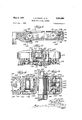
May Z, 1961 L.. R. PElLl-:T ETAL BRUSH WITH STROKE COUNTER 7 Sheets-Sheet 1 Filed Aug. l, 1958 74 www m TF.. A
May 2, 1961 R. PEILETI ErAL BRUSH WITH STROKE COUNTER Filed Aug. l, 1958 Z3 fl l/l/lll/lllllllllllllllill/Illll, lll/lll "I1/1v',
7 Sheets-Sheet 2 @2% ff f8 j@ V W4 w mmf '16@ May 2, 1961 L. R. PEILET ErAL 2,981,963
BRUSH WITH STROKE COUNTER Filed Aug. l, 1958 7 Sheets-Sheet 3 M# i 70 44 l m l 9 22 ZF`JL\.7Z ,73 4i 130 Z @9 f W Z0, ll/WW l 115 El Y Y Y if ff@ f @e @wig/Z5.
May 2, 1961 1 R. PEILET ETAL BRUSH WITH STROKE. COUNTER 7 Sheets-Sheet 4 Filed Aug. l. 1958 zza wv A May 2, 1961 L. R..PE|LET ETAL 981953 BRUSH WITH STROKE COUNTER Filed Aug. 1, 1958 7 SheetsSheet 5 l )l T xif, l\\ 'l/l/l 153 Mmm 11% MIZ/M! #LTT /f x'lmmwl 206 73 136 i@ 1% @f2 130 36 230 236 30 May 2, 1961 1 R. PEILET ErAL BRUSH WITH STROKE COUNTER 7 Sheets-Sheet 6 Filed Aug. l, 1958 k "l I l li u u ll Il illlilu May 2, 1961 L. R. PElLr-:T ErAL BRUSH WITH STROKE COUNTER 7 Sheets-Sheet '7 Filed Aug. l, 1958 WNN.
www
MQQN
United States Patent() BRUSH WITH STROKE COUNTER Lester R. Peilet, Tucson, Ariz., and Philip Kaye, Norridge, and Edward E. Tate, Chicago, Ill., assignors, by mesne assignments, to Lester R. Peilet, Hillsborough,
Filed Aug. 1, 1958, Ser. No. 752,520
35 Claims. (Cl. 15-105) This invention relates to brushes and is applicable to brushes in general, but finds particular application to hair brushes.
One object of the present invention is to provide a new and improved brush having means therein for counting the strokes taken with the brush.
A further object is to provide a new and improved hair brush which will count the strokes taken by the user through his or her hair, the brush being especially valuable to persons who are accustomed to brush their hair regularly with one hundred strokes, or some other arbitrary number of strokes, in order that the hair will always be in good condition and well groomed.
It is another object to provide a new and improved brush adapted to count the strokes of the brush in an automatic manner, without close attention by the user, so that the strokes will be counted while the brush is used in the normal manner, without any added burden or responsibility on the user.
A further object is to provide a new and improved brush which will register the count of the strokes either visually or audibly, or both.
Another object is to provide a new and improved brush having a stroke-counting mechanism which may be reset to Zero at any time, so that a new sequence of stroke counts may be initiated at will.
Still another object is to provide a new andimproved stroke-counting brush which may readily be manufactured at low cost.
Further objects and advantages of the present invention will appear from the following description, taken with the accompanying drawings, in which:
Fig. l is a plan view showing the top or back of a stroke-counting brush to be described as one illustrative embodiment of the present invention.
Fig. 2 is a fragmentary enlarged top plan view with various parts broken away and shown in section.
Fig. 3 is an elevational sectional view taken generally along a line 3 3 of Fig. 2.
Fig. 4 is a horizontal ysection of the brush, viewed upwardly from the bottom or bristle side thereof, and taken generally along a line 4--4 in Fig. 3.
Fig. 5 isa fragmentary enlarged elevational section taken along a line 5-5 in Fig. 4 to showV a portion of the stroke-counting mechanism.
Fig. 6 is a fragmentary enlarged elevational section taken along a line 6-6 in Fig. 4.
Fig. 7 is a fragmentary perspective view showing a portion yof the sounder mechanism whereby the stroke count is indicated audibly in the brush of Fig. 1.
Fig. 8 is an elevational section taken along a line 8--8 in Fig. 2 to show details of the counter mechanism.
Fig. 9 is an elevational section showing details of the sounder mechanism and taken generally along a line 9-9 in Fig. 2. Y f
Fig. 10 is afragmentary enlarged elevational section similar4 to the left-hand portion of Fig. 3.
Fig. 11 is asideelevational view 'ofv a modified stroke-l 2,981,963 k"Patent-'ed vMay 2, ,1961
counting brush to be described as a second embodiment of the present invention.
Fig. 12 is a plan view showing the top or back of th brush of Fig. 11.
Fig. 13 is a fragmentary enlarged horizontal section taken generally along a line 13-13 in Fig. l1, to show details of the stroke-counter installed in the handle of the brush.
Fig. 14 is a transverse elevational section taken along a line 14-14 in Fig. 13, this line also being shown in Fig. 16.
Fig. 15 is an elevational view showing the rear or inner end of the handle of Fig. 13, with the reset knob removed for clarity of illustration.
Fig. 16 is an elevational section taken generally along a broken line 16-16 in Fig. 12.
Fig. 17 is a transverse elevational section taken along a broken line 17-17 in Fig. 16.
Fig. 18 is a fragmentary enlarged elevational section taken generally along a line 18--18 in Fig. 13.
Fig. 19 is a fragmentary enlarged horizontal section 'taken generally along a broken line 19-19 in Fig. 18.
Fig. 20 is a fragmentary bottom View of a modified stroke-counting brush somewhat similar to that of Figs. 1-10, certain parts of the brush being removed or broken away in the view.
Fig. 21 is a fragmentary elevational section taken generally along a line 21-21 in Fig. 20.
Fig. 22 is an elevational section taken generally along a broken line 22-22 in Fig. 20. Y
It will be apparent that Figs. 1 10 illustrate a brus 2t) which may be used for various purposes, but finds its best application as a hair brush. Thus, the brush 20 has a plurality of bristles 22, indicated diagrammatically in Fig. 3. The illustrated 'bristles 22 are mounted on a plate or othersuitable mounting member 24.
The illustrated brush 20 is provided with relatively movable elements which are adapted to lbe moved as the brush is employed in the normal manner by the user in carrying out brushing strokes through the hair or the like. A counter device mechanism 26 is provided in the brush 20 to count the movements of the relatively movable elements, and thereby obtain a count of the strokes taken with the brush. In the illustrated brush, the bristle-mounting member 24 constitutes one of the movable elements. The other movable element takes the form of a grip portion 28 which is held in the hand of the user when he or she manipulates the brush. It will be seen that the grip portion 28 is shown as a handle which is formed integrally with or otherwise secured to a portion 30 constituting the body or head of the brush 20. It will be understood that the handle 28 might be omitted, in which case the body 30 would function as the grip portion, adapted to be held in the hand of the user.
As already indicated, the bristle-mounting member or plate 24 is movable relative to the handle 28 and body 30. The brush might provide for varioustypes of relative movement, such as translatory, rotary, swingingor rocking movement, for example. In this instance, the bristle plate 24 is swingable about a pivot pin 32 connected thereto near the rear or inner end thereof. It will be seen that the pin 32 extends through a hole 34 in a lug 36 or the like extending rearwardly from the bristle plate 24. The illustrated handle 28 is hollowed out adjacent the body 30 to form spaced lateral walls 3S between which the lug 36 is received. Mounting holes 40are formed in the walls 38 to receive the pin 32. The tit between .the
' through the hair or the like.
.biasing action is provided by a coil spring 52 compressed Vsingle or multiple disc, drum, or belt type.
. 3 pound 42,. which also retains the pin and improves the appearance of the brush.
The bristle-mounting plate 24 is received in the lower It'will be apparent that the plate 24 is swingable in and out i through quite a limited range, between upper and lower stops 46 and 48 formed on the outer end of the body '.30 and extending into the cavity 44. The plate 24 has its outer end formed into alip or ange 50 which is `movable between the stops 4-6 and 48.
It is preferred to have the bristle-mounting plate 24 'biased outwardly so that it will return to its outer position after being pushed inwardly by the normal pressure applied to the bristles 22 during each stroke taken In this case, the outward between the plate 24 and the body 30. The spring 52 is adapted to be advanced step by step by the in-and-out movement of the bristle-mounting plate 24. Various means might be provided to advance the wheel 58, but in this case, the wheel has a downwardly projecting peripheral ange 60 formed with ratchet teeth 62. An actuating ipaWl 64 is provided to advance the ratchet wheel 5S.
A second pawl 66V is preferably provided to prevent retro gradefor reverse movement of the wheel 58 during the counting operation.
As illustrated, the counting wheel 58 is rotatably mounted on a stud or spindle 68 formed on the body 30 and projecting downwardly into the cavity 44. The pawls 64 and 66 take the form of slanting teeth or eiingers formed on flat springs 70 and 72 which also are rotatably mounted on the stud 68. Three washers 74 are provided on the stud 68 and are located above the .spring 72, between the springs 70 and 72, and below the spring 70. A collar or clip 76 is suitably secured to the lower end of the stud 68 to retain the wheel 58,
`pavvl'springs 70 and 72, and washers 74. The outer end of the pawl spring 72 is received between stops 78 and 80 (Fig. 4) Von the body 30 to prevent the non-retrograde pawl 66 from rotating about the stud 68 to any substantial extent.
Various arrangements might be provided for operating the advancing'pawl 64 in response to the inward and outward movement of the bristle-supporting plate 24. In this instance, the operating connection is provided by a cam 82 which takes the form of a cylindrical pin fixedly mounted in a bore 84 formed in the plate 24. To provide the desired camming action, the pin 82 is arranged to slant laterally while projecting upwardly .I from the plate 24. It will be seen that the upper portion of the pin 82 extends through a slot or hole 86 formed "in the actuating pawl spring 70. From Fig. 5, it will be apparent .that upward movement of the bristle plate 124 will cause the pin 82 to cam the pawl spring. 'l0 to the left, while downward movement of the plate 24 will return the pawl spring 70 to the right. In Fig. 5, the
To prevent overtravel of the wheel 58'V andkto provide vassumes is located in a boreror recess 54 Vfacing downwardly into .for convenient resetting of the wheel, it is preferred to bias the wheel in a reverse direction toward its zero or starting position. As shown to best advantage in Fig. 2, 3 and l0, the illustrated wheel 58 is biased by a return spring ofthe spirally coiled type. The inner end of the spring 90 is retained in a slot 92 formed in the stud 68. Near its outer end, the spring 90 is retained behind a hook 94 formed on the counting wheel 58. The spring 90 is initially :stressed so as to bias 'the wheel 53 toward its starting position. The biasing action is in a reverse direction with respect to the advancing movement of the wheel 58.
A stop arrangement is provided to prevent the spring 98 from returning the wheel S8 beyond its zero or starting position. in this case, the spring-90 has en outer stop portion 96 which projects radially in an outward direction through a hole 9'/ formed in the ange 60 on the wheel 58. The stop portion 96 is engageable with a stop 98 provided in the body 30. Between the flange 60 and the hooi; 94, the spring 90 has a half-turn or loop 100 (Fig. 2) which prevents the outer stop portion 96 from being withdrawn inwardly through the hole 97. y
It will be understood that the number oi ratchet teeth 62 provided on the wheel 58 will correspond generally to the maximum count to be registered by the wheel. Because of the common practice of giving the hair 100 strokes, the illustrated wheel 58 is arranged to count to 100. A few extra teeth are preferably provided on the wheel so that the count of 10G is achieved in slhtly less than onek revolution of the wheel. Thus, for example, the wheel may have 104 ofthe ratchet teeth 62.
The count registered by the wheel 58 may be indicated visually by providing suitable index means 102 on the wheel. From Fig. 2, it will be apparent that the index means take the form of a graduated angular scale' on the wheelSS. The graduations of the scale may be numbered from zero to 100, as shown. A window 104 is preferably provided in the body 30 so that the scale 102 will be readily visible. As shown to best advantage in Fig. 1, a xed hair line or other index mark 106 is provided on the window 104 for convenience in reading the scale 102 accurately.
During the advancing movement of the wheel 58, the action of the ratchet pawls 64 and 66 will provide clicking sounds which will indicate that the count is progressing toward 100. It will be understood that the nonretrograde pawl 66 springs downwardly and snaps behind the next tooth 62 for each count. On the return movement of the actuating pawl spring 70, the actuating .pawl 64 springs downwardly and snaps behind the next tooth 62 to be acted upon. These snapping movements of the pawls provide the audible clicks. Thus, the inherent 'action of the ratchet mechanism provides audible sounds to indicate that the count is progressing. From Fig. 2,'it will be apparent that the iixed stop 9S is engaged by the stop portion 96 on the wheel 58 so as to arrest the movement of the wheel slightly short of one revolution. At this'point, the audible clicks produced by the ratchet pawls 64 and 66 will cease. This in itself would give an indication to the user that the count of 100 has been reached.
However, it is preferred to provide an additional sounderV 108 which operates -at the count of 100 so as to provide a positive indication that the desired count has been reachedf From Fig. 2, it will be apparent that the illustrated sounder 108 employs a bell 110 adapted to be struck by a'hammer 112. A movable pawl 114 is connected to the hammer 112 and is adapted to be tripped by the stop portion 96 at the count of 100.
YIn the illustrated construction, the hammer F112 is mounted on the outer end of a spring arm 116 which forms one .portion of a hairpin-type spring 118 wrapped around a pivot or stud 1,20on the body 30. The spring 118 has a second arm 122 whichbears againsttheinner 75 wallbf Ythe cavityV 44.' It will be seen that the springarm 116 extends through a hole 124 rin a levery 126. Normally, the spring 118 biases the lever 126 against a stop 128. The pawl 114 takes the form of the slanting outer end portion of a at pawl spring 130 which is secured to the outer end of the lever 126 and extends generally at right angles thereto. The pawl spring 130 is backed up on one side by a ange 132 formed on the lever 126,
With respect to the outwardly extending pawl spring 130, the pawl 114 slants inwardly and laterally in the direction from which the radially projecting stop portion 96 approaches the pawl. In passing the pawl 114, the stop portion 96 cams the pawl to the right, as seen in Fig. 2, and thus causes the lever 126 and the hammer arm 112 to swing clockwise. When the stop portion 96 moves past the pawl 114, the spring 118 returns the lever 126 abruptly in a counterclockwise direction and thereby causes the hammer 112 to Hex the spring arm 116 and strike the bell 110. The sounding of the bell indicates that the desired count has been reached.
Various means might be provided to reset the counting wheel 58 to its zero or starting position. As already indicated, the illustrated wheel 58 is adapted to be returned bythe biasing spring 90. However, the wheel might be arranged to be returned manually without the aid of a return spring, or even againstthe action of a windup spring, in which case the pawl mechanism would be replaced with an escapement to provide for advancing movement of the wheel.
The illustrated counter 26 is adapted to be reset simply by pressing a reset button 134 extending upwardly from the top of the body 30 through a hole 136. The illustrated button 134 has a lower end portion 138 which is enlarged to prevent upward movement of the portion 138 through the hole 136. In this case, the lower portion 138 is generally rectangular and is coni-ined between the stops 78 and 80. It will be seen from Fig. 3 that the lower portion 13S of the button 134 is supported by the outer end portion 140 of the non-retrograde pawl spring 72. This outer portion 140 extends outwardly beyond the actuating pawl spring 70. When the button 134 is pushed downwardly, the spring 72 is exed downwardly `to disengage the non-retrograde pawl 66 from the ratchet teeth 62. In the initial stage of its downward movement, the spring 72 engages the spring 70 so that full downward movement of the button 134 will also disengage the actuating pawl 64 from the ratchet teeth 62. In this way, the ratchet Wheel 58 is released for return movement by the return spring 90. The wheel 58 may be released in any position to which it may have been advanced. If the wheel is released after the stop portion or prong 96 has passed the pawl 114 which actuates the sounder 108, the prong 96 will snap past the pawl 114 by flexing the pawl spring 130 away from the backing flange 132.
The operation of the brush imposes no additional responsibility or duty upon the user, other than the need to reset the counter initially and to listen for the sounder 108. As just explained, ther counter 26 is reset by pressing the button 134, which disengages the actuating and nonretrograde pawls 64 and 66 from the ratchet teeth 62. The wheel 58 is thus released for return movement by the spring 90. v
The brush is used in the normal manner by stroking the bristles 22 through theV hair. The pressure on the bristles 22 swings the bristle plate 24 upwardly relative to the body 30 and handle 28. Such movement of the plate 24 causes the pin 82 to cam the-actuating pawl 64 to vthe left, asseen in Fig. 5. The pawl 64 'thereby advancesthe kwheel 5S through an angle corresponding to the spacing of the ratchet teeth 62. It will be apparent that the non-retrograde pawl 66 catches the 'next ratchet tooth and prevents reverse rotation of the wheel 5,8. When the pressure on the bristles 22 is released, the spring 52 lswingsy the bristle plate 24 downwardly. The
drum, or belt type.
In this Way, the` wheel l58 is advanced step by step. The count registered by the wheel 58 may be read at any time by observing the scale 102 through the window 104.
When the count of is reached, the stop or prong 96 trips the pawl 114 and thereby causes the hammer 112 to strike the sounder bell 110. This indicates that the desired number of strokes have been made and that the counter 26 should be reset by pressing the button 134.
Figs. 11-19 illustrate the modified stroke-counting brush to be described as a second illustrative embodiment of the present invention. Here again, the brush 150 comprises a bristle-mounting member 152 and a grip member 154 which are relatively movable in response to the normal stroking action of the brush. A counter 156 is provided in the brush to count the cycles of relative movement between the members 152 and 154 and thereby obtain a count of the strokes taken with the brush.
In this case, the bristle-supporting member 152 takes the form of the entire body or head of the brush. A plurality of bristles 158 are suitably mounted o-n the lower side of the body 152.
The grip member 154 takes the form ofa handle connected to the body 152 in such a manner as to provide for relative movement between the handle and the head. Various types of relative movement mightbe utilized, such as translatory, swinging, or swiveling movements. It will be apparent that the illustrated head 152 is swingable through aA limited range relative to the handle 154. Thus, a pivot or hinge pin 160 is employed to connect the handle 154 to the head 152. The head 152 has a lug 162 thereon which is received between a pair of spaced lugs 164 and 166 on the handle 154. The pin 160 extends through bores 168, and 172 in the members 162, 164, and 166, respectively. The pin 160 may befrietionally retained in the bores 170 and 172.
To limit the range of swinging movement between the headV 152 andthe handle 154, opposed closely spaced flat faces 174 and176 are provided thereon. The face 174 is on the end of the lug 162, while the face 176 extends between the lugs 164 and 166 on the handle 154. It will be apparent from Fig. l1 that upward swinging movement of the head 152 relative to the handle 154 is limited by engagement of the upper portions of the faces 174 and 176. The head 152 has a finger 178 thereon which extends from the lug 162 under the handle 154 and is engageable with the under side thereof to limit downward swinging movement of the head 152 relative to the handle 154. f
It will be apparent that normal stroking of the bristles 158 through the hair or the like will apply pressure to the bristlesl so as to swing the head 152 upwardly relative to the handle 154. When the pressure is released, the
biasing action of gravity. It will be apparent that a spring or other resilient element may be provided to enhance the ybiasing action of gravity, if desired. f
The cycles of upward and downward swinging movement of the head 152 are employed to operate the counter 156. Here again, thecounter may be of` any suitableconstruction, such as the single or multiple disc,
The illustrated counter 156 ernploys a single register belt 180.*which is threaded around two spaced drums 182 and 184. One edge of the belt ,has spaced perforations 186 therein to receive sprocket teeth 188 and 190 on the respective drums 182 and 184. It will 4he apparent that they belt 130 runs longitudinally within a cavity 192r formed 'in the handle 154. The drums 182 and 184 are parallel to each other and extend crosswise in the longitudinal cavity 192.' `As shown, the drums 182 and 184 are lrotatable about horizontal pins 194 and 196 which are received in holes 198 'and -200 formed in the handle 154. 'nsr d Various means may be provided to 'connect the ,head
. 7 1j52vto the counter 156 so that the swinging movement 4of the head will advance the register belt 180. In`this instance, a ratchet mechanism is provided. Thus, a ratchet wheel 202 is secured to one `end of the drum 182 jand'is adapted to be advancedby a pawl 204 pivoted on the finger 178 which extends from the head 152 under the end portion ofthe handle 154. Thus, a pivot pin v206 is employed to mount the pawl 264 on the finger 178. A spring 208 biases the pawl against the ratchet wheel 202.
When the head 152 is swung upwardly, the pawl 204 is pulled downwardly. This advances the ratchet wheel 202 by an amount corresponding to the spacing between the ratchet teeth. The belt 180 is thereby advanced one i step. On the downward movement of thehead 152, the ipawl 204 ratchets upwardly to catch the next tooth on the ratchet wheel 202. The bearing friction on the drums 182 and 184 may be made sucient to prevent retrograde movement of the ratchet wheel 202,
The advancing movement of the belt 180 may be in- "dicated visually by providing suitable index means 210 on the belt. The illustrated index means take the form of a scale, which may be numbered from zero to 100, or any other desired and suitable number. The scale A210 is visible through a window 212 in the upper side of the handle 154. An index mark 214 may be provided on the window 212`to facilitate thereading of lthe scale 210. l n
Various means may be provided for resetting the'belt 180 to zero. The illustrated counter 156 utilizes a manually rotatable reset knob 216 which is rotatably mounted on a generally cylindrical stud 218 secured to the rear end of Vthe handle The illustrated knob 216 is formed with a gear portion 220 adapted to mesh with the sprocket teeth 190 ou the vdrum 184. While the gear 220 might be in mesh with the sprocket teeth at all times, it is preferred to arrange the knob 216 so that the gear `portion 220 is normally disengaged from the teeth 1%.
Thus, the knob 216 is arranged to be slid endwise on the stud 218. The knob is normally biased outwardly by a rresilient element in the forrnkof a spring 222 disposed in Aa socket 224 formed in the end of the stud 218., The knob 216 is generally cup shaped and thus is formed with an end wall 226. A ball 228, acting as a thrust bearing, is interposed between the spring 222 and the end wall 226. It will be apparent from Fig. 16 that the knob 216 may be pushed inwardly to engage the gear portion 220 with the sprocket teeth 190.
To retain the knob 216 on the stud 218, while providing` for endwise sliding movement of the knob, a retaining pin 230 is titted into a bore 232 formed in the knob 216. The Vpin 230 is received in an annular groove 234 formed in the stud 218. it will be seen from Figs. 16
and 19 that the groove 234 is of a width substantially greater than the diameter of the pin 230 so that the knob 216 may be slid endwise. Fig. 16 illustrates the knob 216 in its'outwardly biased position, while Fig. 19 shows the knob in its inwardly pushed position, with the gear 220 meshing withthe sprocket teeth 190.
In operating the brush, the user should tirst reset the counter 156 to zero byfpushingrthe knob 216 inwardly and then rotating the knob so that the gear portion 220 will drive the sprocket portion 190 of the drum 184. The
knob is rotated in such a direction that the ratchet wheel 202 will ratchet over the pawl 204. By observing the scale 216 on the belt 180, the `counter may be reset to zero.
The brush 150 is then used in the normal manner for *brushing the hair or the like. On each stroke of the K brush, thehead 152 swings upwardly and downwardly v relative to the handle 154. On the upward movement of the head 152, the `pawl 2041is pulled downwardly so as to advance the ratchet wheel 202 and the belt 180.V The I downward ymovement jof the 4head152w causes the. pawl 204 to ratchet along thel wheel 202 so as to tcatch the next ratchet 'tooth thereof. From time to timefih'e user may read the scale 210 on the belt 180 so as :to
what modified counting mechanism 252. Manyof the components of the modified brush 250 are essentially the same as in Figs. 1-10, and, to that extent, the components in Figs. 20-22 have been given the same reference characters as in Figs. 1-10. The following description will emphasize the differences between the modified brush 250 and the brush of Figs. 1-10.
One of the important modifications illustrated in Figs. 20-22 resides in the provision of a counting pawl 254 which is mounted on the bristle plate 24 and is adapted to advance the ratchet wheel 58 as the bristle plate is swung back and forth in brushing the users hair or the like. The counting pawl 254 replaces the counting pawl 64 of Figs. l-lO.
The counting pawl '254 may be arranged in various ways. However, as shown to best advantage in Figs. 21 and 22, the illustrated pawl 254 is geherally L-shaped and is provided with two fingers or arms 256 and 258 which radiate from a hub or pivot member 260 having a bore 262 thereon. As shown, the arms 256 and 258 are `at an angle of somewhat less than 90 degrees to each other.
In this case, the counting pawl 254 is loosely pivoted on the bristle plate 24 at a point underlying the toothed flange 60 on the ratchet wheel 58. The hub portion 260 "of the counting pawl 256 is received between a pair of apertured lugs 264 which may be molded or otherwise formed on the bristle plate 24. A pivot pin 266 is utilized to retain the hub portion 260 between the lugs 264 for swinging movement. The illustrated pawl 256 is biased counterclockwise (Fig. 22) or upwardly by a spring 267.
1n general, the arm 256 isadapted to be swung back and forth by the swinging movement of the bristle plate `24, while the arm or finger 258 is arranged to engage the ratchet teeth 62 on the ratchet wheel 58. Thus, the arm 256 extends at a small angle to the top of the bristle plate 24, as clearly shown in Fig. 22, and is adapted to be operated by a pin 268 tixedly mounted on the body 30 of the brush. As clearly shown in Fig. 2l, the pin 268 extends downwardly toward the bristle'plate 24 from the top wall of the'body 30. When the bristle plate 24 is swung upwardly by the application of brushing pressure to the bristles 22, the arm 256 is pushed downwardly by the pin 268, against the biasing action of the spring 267. This swings the pawl 254 in a clockwise direction, as seen in Fig. 22.
The illustrated arm or nger 258has an edge 270 which is adapted to engage each of the ratchet teeth 62 in succession. As shown, the edge 270 is generally chisel- Vshaped in lform, for entry into the notches between the ratchet teeth 62.
r1`he stroke counting brush 250 of Figs. 20-22 also is equipped with a modied nonretrograde pawl 272 which replaces the pawl 66 of Figs. 1410. As shown to best advantage in Fig. 20, the pawl 272 is generally in the form of a flat-spring which is secured to theA top wall of the body 30 by means of a suitable anchoring device 274.y The pawl 272 extends generally in a tangential di- /rection relative to the ratchet wheel 58. An ear 276 wardly soas to -oier a minimum of resistance to the advancing' movement.
`As in the case of the brush of Figs. l-lO, the ratchet wheel 58 is returned to its initial position by disengaging the nonretrograde pawl 272 from the ratchet wheel. This is accomplished by pushing the button or plunger 134 downwardly. The pawl 272 has an outer end portion 280 which supports the button 134 and is movable downwardly between the lugs 78 and 80. When the button 134 is pushed downwardly, the pawl 272 is flexed in a downward direction and thereby is disengaged from the ratchet teeth 62. t
The ratchet wheel 58 has a hub portion 284 which is much the same yas that provided in Figs. 1-10. It will be seen from Fig. 21 that the hub portion 284 is rotatably mounted on a post 286. In this case, the post 286 is formed as a separate piece having a head or tiange 288, adapted to be mounted in a recess or cavity 290 formed in the top wall of the body 30. The flange 288 may be cemented, press-fitted, or otherwise retained in the cavity 290.
In this case, the hub portion 284 of the ratchet wheel 58 is simply slipped over the post 286. A washer 292 may be slipped onto the post 286 below the hub portion 284, so as to separate the hub portion from they return spring 90. A .diametrical hole 294 is formed in the post 286 to receive the inner ends of the return spring 90. It will be apparent that the spring 90 retains the washer 292 on the post 286.
In the operation of the modified brush 250, the bristle plate 24 is swung up and down as the brush is stroked through the hair. The application of brushing pressure swings the plate 24 up, while the spring 52 returns the plate down, in the same manner as for the brush of Figs. 1-10.
In the modified brush 250, the upward movement of the bristle plate 24 causes the pin 268 to swing the pawl 254 clockwise, against the action of the spring 267. It will be apparent from Fig. 22 that the upward movement of the bristle plate 24, plus the clockwise swinging movement of the pawl 254, brings the actuating edge 270 of the finger 258 against each successive tooth 62 of the ratchet wheel 58. The swinging movement of the pawl 254 is sufficient to advance the ratchet wheel 58 through an anglecorresponding to the spacing between the ratchet teeth. It will be apparent that the non- `retrograde pawl 56 prevents return movement ofthe ratchet wheel 58. Thus, the disc or wheel 58 effectively registers the count of the stroking cycles. As in the brush of Figs. 1-10, the count may be read through the window 104. After a predetermined count, the disc 58 may operate a sounder or other signal device.
To reset the modied stroke-counting brush 250, the user presses the button 134 so as to flex the nonretrograde pawl 272 downwardly and thereby disengage the pawl 272 from the ratchet disc 58. The spring 90 is then effective to return the disc 58 to its starting position. In this case, the counting pawl 254 is normally out of engagement with the ratchet teeth 62, so that there is no need for the button 134 to disengage the counting pawl from the ratchetwheel.
It will be apparent that the illustratedl stroke-counting brushes operate automatically to count the strokes taken with the brush during normal brushing of the hair or the like. There is no need for the userto keep track of the count. The counter devices inthe brushes indicate the count `either visually or audibly, or in both manners. The user may readily reset the counter of each brush to zero to kstart a new stroke-counting sequence. t
The brushes are eiectiveand dependable in operation,
and are so sturdy asjto .last indefinitely. With all of these advantages, the brushes may be readily manufactured at low cost.
f ,Yarious other modifications, alternative constructions v andi equivalents may be employed withoutdeparting from ythe true spirit and scope offftheinvention, as exempli- N tied in the' foregoing description and defined in the'fol lowing claims.
We claim: Y
1. In a brush, the combination comprising a bristle mounting member with a plurality of bristles thereon, a grip member movably connected to said mounting member, stop means limiting the range of relative movement between said grip member and said mounting member, said mounting member being movable back and forth relative to said grip member in response to the repeated manual application of brushing force between said grip member and said mounting member, and counter means for counting the cycles of relative movement between said members and thereby counting the brushing strokes.
2. In a brush, the combination comprising a bristle mounting member with a plurality of bristles thereon, a grip member movably connected to said\mounting member, stop means limiting the range of relative movement between said grip member and said mounting member, said mounting member being movable back and forth relative to said grip member in response to the repeated manual application of brushing force between said grip member and said mounting member, and counter means for counting the cycles of relative movement between said members and thereby counting the brushing strokes, said grip member comprising a body with a hand grip portion thereon, said mounting member being movably mounted on said body. Y
3. In a brush, the combination comprising a bristle mounting member with a plurality of bristles thereon, a grip member movably connected to said mounting member, stop means limiting the range of relative movement between said grip member and said mounting member, said mounting member being movable back and forth relative to said grip member in response to the repeated manual application of brushing force between said grip member and said mounting member, and counter means for counting the cycles of relative movement between said members and thereby counting the brushing strokes, said grip member comprising a body with a hand grip portion thereon, said mounting member comprising a plate with pivot means mounting said plate in said body lfor in-and-out swinging movement responsive to brushing pressure on said bristles.
4. In a brush, the combination comprising a bristle mounting member with a plurality of bristles thereon, a grip member movably connected to said mounting member, stop means limiting the range of relative movement between said grip member and said mounting member, said mounting member being movable back and forth relative to said grip member in response to the repeated manual application of brushing force between said grip member and said mounting member, counter means for counting the cycles of relative movement between said members and thereby counting the brushing strokes, said grip member comprising a body with a hand grip portion thereon, said mounting member comprising a plate with pivot means mounting said plate in said body for in-and-out swinging movement responsive to brushing pressure on said bristles, and resilient means biasing said plate outwardly relative to said body.
5. In a brush, the combination comprising a bristle mounting member with a plurality of bristles thereon, a grip member movably connected to said mounting member, stop means limiting the-range of relative movement betweensaid grip member and said mounting member,
said mounting member being movable back and forth relative to said grip member in response to the repeated manual application of brushing force between said grip member and said mounting member, counter means for counting ythe cycles of relative movement betweensaid members and thereby counting the brushing strokes, and yieldable means biasing said mounting member in one `direction of movement relative toy said grip member.
' '6. 'n l'abrush, the combination comprising a bristle mounting member with a plurality of bristles thereon, a grip member movably connected to said mounting mem- Aber', stop means llimiting 'the range of relative movement between said grip member and said mounting member, said mounting member being movable back and forth relative to said grip member in response to the repeated manual application of brushing force between said grip member and said mounting member, and counter means vfor counting the cycles of relative movement between said members and thereby counting the brushing strokes, said mounting member comprising a body, said grip member comprising a handle movably mounted on said body.
7. In a brush, the combination comprising a bristle "mounting member with a plurality of bristles thereon, a -grip member movably connected to said mounting member, stop means limiting the range of relative movement between said grip member and said mounting member, said mounting member being movable back and forth l'relative to said grip member in response to the repeated manual application of brushing force between said grip member and said mounting member, and counter means for counting the cycles of relative movement between vsaid members and thereby counting the brushing strokes, said mounting member comprising a body, said grip `member comprising a handle with pivot means connecting said handle to said body for relative swinging moveement. i
8. In a brush, the combination comprising a bristle mounting member with a plurality of bristles thereon, a 1 grip member movably connected to said mounting member, stop means limiting the range of relative movement between said grip member andsaid mounting member, lsaid mounting member being movable back and forth Vrelative to said grip member in response to the repeated :manual application of brushing force between said Vgrip member and said mounting member, and counter means for counting the cycles of relative movement between 'said'members and thereby counting the brushing strokes, said counter means comprising register means and means for eftecting step-by-step movement of said register means responsive to relative movement between said members. 9. In a brush, the combination'comprising a bristle mounting member with a plurality of bristles thereon, a grip member` movably connected to said mounting member, stop means limiting the range or relative movement between said grip member and said mounting member, vsaid mounting member being movable back and forth .relative to said grip member in response to the repeated Ymanual application of brushing force betweensaid grip member and said mounting member, counter means for counting the cycles of relative movement between said members and thereby counting the brushing strokes, said A manual application'of brushing force between said grip' member and said mounting member, counter means for *counting the cycles of relative movement between said lmembers and therebyA counting the brushing strokes, said counter means comprising register means and means for effecting step-by-step'movement of Hsaid register means responsive to relative movement Between said members, f'a return spring biasing said register means ltoward a predetermined starting position,A and means forrele'asing rsaid' register meansforreturn movement by said spring to said starting position.
1l. In a brush, the combination comprising a bristle mounting member with a plurality of bristles thereon, a
`-gripmember movably connected to` said mounting member, stop means limiting the range of relativemovement lbetween said grip member and said mounting member,
responsive to relative movement between said members,
and a manually operable Vreset element engageable with said register meansfor returning said registerv means to a predetermined starting position. Y
12. In a brush, the combination comprising a bristle mounting member with a plurality of bristles thereon, a
grip member movably connected to said mounting member, stop means limiting therrange of relative movement Vbetween said grip member and said mounting member,
said mounting member being movable back and forth relative to said grip member in response to the repeated manual application of brushing force between said grip member and said mounting member, 'and counter means for counting the cycles of relative movement between said membersand thereby counting the brushing strokes,
lsaid counter means comprising signal means for signal- `ring the count of said counter means.
i3. In a brush, the combination comprising a bristle vmounting member with a plurality of bristles thereon, a
grip member movably connected to said mounting member, stop means limiting the range of relative movement Vbetween said grip member and said mounting member,
said mounting member being movable back and forth relative to said grip member in response to the repeated manual applicationfof brushing force between Sad grip member and saidV mounting member, counter means for counting the cycles of relative movement between said members and thereby counting the brushing strokes, said -counter means comprising register means and means for effecting step-by-'step'movement of said register means responsive to relative vmovement between said members, 'and sounder means for 'producing an audible signal responsive to predetermined-movement of said register means. Y Y
14. VIn aV brush, the combination comprising a bristle mounting member lwith a plurality of bristles thereon, a grlp member 'movably connected to said mounting member, stop means limiting the range of relative movement between said grip member and said mounting member, sald 'mounting member being movable back and `forth relative' to said gripmember in response to the repeated manual-application'of brushing force between said grip member and said mountingmember, and counter means for counting the cycles of relative movement between said members andthereby counting the brushing strokes,
said counter means comprising a movable ratchet member, a return spring biasing said.4 ratchet member toward `a predeter'minedY starting position, an advancing pawl Yoperablev by `r'ela'tive"mover'nent between said grip and mountingV members forv advancing said ratchet member,
' afs/econd p'awl for lrestrainingreturn movement of said i ratchet member, andaneans for disengaging said pawis and said ratchet member and thereby releasing said i ratchet member for return movement by said spring.
175. In brush, fthe'combination comprising a brietie -mounting member with a plurality of'bristles thereon, a
grip member movably connected to said mounting'member, stop means-limiting lthe range'of relative movement A "between said grip" member and Vsaid mounting member,
said mounting nieinbervbeingfmovable back and-f forth relative to said grip member in response to the repeated manual application of brushing force between said grip member and said mounting member, and counter means for counting the cycles of relative movement between said members and thereby counting the brushing strokes, said counter means comprising a movable ratchet member, a return spring biasing said ratchet member toward a predetermined starting position, an advancing pawl operable by relative movement between said grip and mounting members for advancing said ratchet member, a second pawl for restraining return movement of said ratchet member, a sounder operable by said ratchet member upon predetermined advancing movement thereof, and means for disengaging said pawls and said ratchet member and thereby releasing said ratchet member for return movement by said spring.
16. In a brush, the combination comprising a bristle mounting member with a plurality of bristles thereon, a grip member movably connected to said mounting member, stop means limiting the range of relative movement between said grip member and said mounting member, said mounting member being movable back and forth relative to said grip member in response to the repeated manual application of brushing force between sad grip member and said mounting member, and counter means" for counting the cycles of relative movement Vbetween said members and thereby counting the brushing strokes, said counter means comprising a movable ratchet member, a return spring biasing said ratchet member toward a predetermined starting position, an advancing pawl operable by relative movement between said ygrip and mounting members for advancing said ratchet member, a second pawl for restraining return movement of said ratchet member, said ratchet member having visible index meansthereon for visually indicating the advancing movement thereof.
17. In a brush, the combination comprising a bristle mounting member with a plurality of bristles thereon, a
grip member movably connected to said mounting member, stop means limiting the range of relative movement between said grip member and said mounting member, said mounting member being movable back and forth relative to said grip member in response to the repeated manual application of brushing force between said grip member and said mounting member, counter means for counting the cycles of relative movement between said members and thereby counting the brushing strokes, said counter means comprising a movable register belt, and ratchet means for advancing said belt responsive to relative movement between said grip and mounting members.
18. In a brush, the combination comprising a bristle mounting member with a plurality of bristles thereon, a grip member movablyy connected to said mounting member, Astop means limiting the range of relative movement between Asaid grip memberand said mounting member, said mounting member being movable back and forth relative to said grip member in response to the repeated manual application ofbrushing force between said grip member and said mounting member, counter means for counting the cycles of relative movement between said members and thereby counting the brushing strokes, said counter means comprising a movable register belt, ratchet meansftor advancing said belty responsive to relative movement between isaid grip and mounting members, and selectively operableI gear means for resetting said ybelt to a predetermined starting position.
19. In a brush, the combination comprising a body, a bristle plate, pivot means ymounting said plate in said body for in and outV swinging movement, stop means ylimiting the range of relativeV movement between said said ratchet wheel, a .return spring biasing said wheelA lagainst advancingr movement, `a' second pawl for'restrain- "T4 ing return'rhovement of said wheel, means for operating said actuating pawl responsive to swinging movement of said bristle plate, and means for eifecting disengagement betweensaid pawls and said wheel to release said Wheel for return movement by said return spring.
20. ln a brush, the combination comprising a body, a bristle plate` pivot means mounting said plate in said body for in and out swinging movement, stop means limiting the range of relative movement between said plate and said body, bristles mounted on said plate, a spring biasing 'said plate outwardly, a ratchet wheel rotatable in said body, an actuating pawl for advancing said ratchet wheel, a return spring biasing said wheel against advancing movement, a second pawl for restraining return movement of said wheel, interengageable cam elements on said bristle plate and said actuating pawl for operating said actuating pawl responsive to swinging movement of said bristle plate, and means for effecting disengagement between said pawls and said wheel to release said wheel for return movement by said return spring.
2l. In a brush, the combination comprising a body, a bristle plate, 'pivot means mounting said plate in said body for in and out swinging movement, stop means limiting the range of relative movement between said plate and said body, bristles mounted on said plate, a spring-biasing said plate outwardly, a ratchet wheel rotatable in said body, an actuating pawl for advancing said ratchet wheel, a return spring biasing said wheel against advancing movement, a second pawl for restraining return movement of said WheeL'interengageable cam elements on said bristle plate and said actuating pawl for operating said actuating pawl responsive to swinging movement of said bristle plate, said cam element on said bristle plate comprising a pin slanting relative to the direction of movement of said plate, said cam element on said` actuating pawl comprising a slot receiving said pin, and means for eliecting disengagement between said pawls and said wheel to release said wheel for return ,movement by said return spring.
22. In a brush, the combination comprising a body, a bristle platepiv0t means mounting said plate in said body for Vin and out swinging movement, stop means vlimiting the range of relative movement between said plate and said body, bristles mounted on said plate, a spring biasing said plate outwardly, a ratchet wheel rotatable in said body, an actuating pawl for advancing said ratchet wheel, a return spring biasing said wheel against advancing movement, a second pawl for restrainf ing return movement of said wheel, means for operating said actuating pawl responsive to swinging movement of said bristle plate, a sounder adjacent said wheel, means on said wheel for tripping said sounder upon predetermined advancing movement of said wheel, and means for effecting disengagement between said pawls and said wheel to release said wheel for return movement by said return spring. f
'23,. ln abrush, the combination comprising a body, a bristle plate, pivot means mounting said plate in said bodyffor `in`and out swinging movement, stop means limiting the range or relative movement between said .plate and said body, bristles mounted on said plate, a spring: biasing said plate outwardly, a ratchet wheel rotatable in'said bodyan actuating pawl for advancing said ratchet wheel, a return spring biasing said wheel againstr advancing* movement, a second pawl for restraining kreturn movement of said wheel, means for operating said 'actuating pawl responsive to swinging movement of said bristle plate, said wheel having a scale thereon for visually indicating the advancing movement thereof, and means for effecting disengagement between said pawls and said wheel to release said wheel for return movement by4 said return Spring. g f f 24. ,Ina brush, the` combination'comprising a body, )aj/bristle` plate, pivot-means mounting said plate 'in said @body 1to1- in, andfpout swinging movement, Stop-,means Ylimiting the range of relative movement between said plate and said body, bristles mounted on said plate, a spring biasing said plate outwardly, a ratchet wheel rotatable in said body, an actuating pawl for advancing said ratchet wheel, a return spring biasing said wheel against advancing movement, a second pawl for restraining return movement of said wheel, means for operating said actuating pawl responsive to swinging movement of said bristle plate, and a manually operable reset member .for moving said pawls away from said wheel to release said wheel for return movement by said return spring.
25. In a brush, the combination comprising a body, a bristle plate, pivot means mounting said plate'in -said body for in and out swinging movement, stop means limiting the range of relative movement between said plate and said body, bristles mounted on said plate, a spring biasing said plate outwardly, a ratchet wheel rotatable in said body, an actuating pawl for advancing saidratchet wheel, a return spring biasing said wheel `against advancing movement, a second pawl for restraining return movement of said wheel, interengageable cam elements on said bristle plate and said actuating pawl ,for operating said actuating pawl responsive to swinging movement of said bristle plate, said cam element on said bristle plate comprising a pin slantng relative to theV` direction of movement of said plate, said cam element on said actuating pawl comprising a slot receiving said pin, `a sounder adjacent said wheel, means on saidrwheelfor tripping said sounder upon predetermined advancing movement of said wheel, said wheel having a scale thereon vfor visually indicating the advancing movement thereof,
and a manually operable reset member for moving said 'pawls awayV from said wheel to release said wheel for .return movement by said return spring.
26. In a brush, the combination comprising a head, a plurality of bristles mounted thereon, a handle, pivot means mounting said handle on said body for limited -swinging movement in a plane generally parallel to the general direction of said bristles, first and second spaced parallel drums mounted in said handle near the outer yand inner ends thereof, an endless register belt threaded around said drums and extending generally along the length of said handle, and means operable by swinging movement of said head relative to said handle for turning said first drum and thereby advancing said belt step Vby step.
27. In a brush, the combination comprising a head, a plurality of bristles mounted thereon, a handle, pivot -means mounting said handle on said body for limited #swinging movement in a plane generally parallel to the.
l general direction of said bristles, first and second spaced fparallel drums mounted in said handle near the outer and inner ends thereof, an endless register belt` threaded around said drums and extending generally along the length of said handle, a ratchet wheel on said first drum, and a pawl connected to said head and operable by swinging movement of said head relative to said handle Afor turning said ratchetwheel and thereby advancing said belt step by step. Y Y i 28. In. a brush, the combination comprisingv a head, a. plurality of bristles mounted thereon, a handle, pivot means mounting said handle on said body for limited swinging movement in a plane generally parallel to the general direction of said bristles, first and second spaced parallel drums mounted in said handleA neartheV outer and inner ends thereof, an endless register belt threaded around said drums and Vextending generally along the :length of said handle, and means operable by swinging .rnovement ofsaid head relative to said handle for turning said rst drum and therebyadvancing said beltstep vvby step, said belt having a scale thereon for visually indicating the advancing movement thereof.
29. in a brush, the combination comprising a head, .a plurality of bristles mountedV thereon, a handle, pivot '.mean's mounting said handle on Vsaid'bddyy ,for limited swinging movement in a planelgenerally parallel" to they general direction of 'said bristles, first and-second spaced parallel drums mounted in said handle near the outer and inner endsthereof, an endless register belt threaded Varound said drumsand extending generally alongthe ysaid first gear for resetting said belt.
30. In a brush, the combination comprising a head, a plurality of bristles mounted thereon, a handle, pivot means mounting said handle on said body for limited swinging movement in a plane generally parallel to the general direction of said bristles, first and second spaced parallel drums mounted in said handle near the outer and inner ends thereof, an endless register belt threaded around said drums and extending generally along the length of said handle, means operable by swinging movement of said head relative to said handle for turning said first drum and thereby advancing said belt step by step, a first gear on said second drum, a manually rotatable reset knob having a second gear thereon engageable with said first gear for resetting said belt, and spring means biasing said knob and second gear awayfrom said first gear.
31. In a brush, the combination comprising a head, a plurality of bristles mounted thereon, a handle, pivot means mounting said handle on said body for limited swinging movement in a plane generally parallel to the general direction of said bristles,ffirst and second spaced rparallel drums mounted in said handle near the outer and inner ends thereof, an endless register belt threaded around said drums and extending'generally along the length of said handle, a ratchet wheel on said first drum, a pawl connected to said head and operable by swinging movement of said head relative to said handle for turning said ratchet wheel and thereby advancing said belt step by step, said belt having a scale thereon for visually indicating the advancing movement thereof, a first gear onsaid second drum, a manually rotatable reset knob 'having a second gear thereon engageable with said first gear for resetting said belt, and springs means biasing said knob and second gear away from said first gear.
32. in a brush, the combination comprisinga bristle mounting member with Aa plurality of bristles thereon, a gripjmember, means movably connectingtsaid grip niemberto said mounting member, stop means limiting the range of relative movement between said bristle mounting member and said grip member, said mounting mem- 50- ber being movable back and forth relative to said grip member in response to the repeated manual application of brushing force between said grip member and said mounting member, and means actuated by and in accordance with the cycles of relative movement between said members for providing a signal after a predetermined number of cycles. f
33. in a brush, the combination comprising a body,
a bristle plate, pivot means mounting said bristle plate in said body for in-and-out swinging movement, stop means limiting the range of relative movement between said body and said bristle plate, bristles mounted on said plate, a spring biasing said plate outwardly, a ratchet wheel rotatable in said body, an actuating pawl swingably mounted on said plate and having an actuating finger for engaging and advancing said-ratchet wheel, said pawl having an operating arm thereon, a stop on said body verigageable by said arm for swinging said pawl in a direction to advance said ratchet wheel in response to inward swinging movement of said plate, Va return spring biasing said wheel against advancing movement, a second pawl for restraining return movement of said wheel, and means for disengaging said second pawl from said wheel to release said wheel for return movement by said return spring.
34. in a'brush, the combination comprising a body,
a bristle plate, pivot means mounting said bristle plate in said body for in-and-out swinging movement, stop means limiting the range of relative movement between said body and said bristle plate, bristles mounted on said plate, a spring biasing said plate outwardly, a ratchet wheel rotatable in said body, an actuating pawl connected to said plate for advancing said wheel in response to swinging movement thereof, a return spring biasing said wheel against advancing movement, a second pawl for restraining return movement of said wheel, and means for effecting disengagement between said second pawl and said wheel to release said wheel for return movement by said return spring. I
35. In a brush, the combination comprising a hand grip member, a plurality of bristles, means mounting said bristles on said member for movement relative to said 18 member through a limited range, said bristles being movable back and forth relative to said member in response to the repeated manual application of brushing force between said member and said bristles, and counter means mounted on said member and connected to said bristles for counting the cycles of relative movement between said bristles and said member.
References Cited in the le of this patent UNITED STATES PATENTS
Priority Applications (1)
| Application Number | Priority Date | Filing Date | Title |
|---|---|---|---|
| US752520A US2981963A (en) | 1958-08-01 | 1958-08-01 | Brush with stroke counter |
Applications Claiming Priority (1)
| Application Number | Priority Date | Filing Date | Title |
|---|---|---|---|
| US752520A US2981963A (en) | 1958-08-01 | 1958-08-01 | Brush with stroke counter |
Publications (1)
| Publication Number | Publication Date |
|---|---|
| US2981963A true US2981963A (en) | 1961-05-02 |
Family
ID=25026646
Family Applications (1)
| Application Number | Title | Priority Date | Filing Date |
|---|---|---|---|
| US752520A Expired - Lifetime US2981963A (en) | 1958-08-01 | 1958-08-01 | Brush with stroke counter |
Country Status (1)
| Country | Link |
|---|---|
| US (1) | US2981963A (en) |
Cited By (8)
| Publication number | Priority date | Publication date | Assignee | Title |
|---|---|---|---|---|
| US3104056A (en) * | 1959-06-29 | 1963-09-17 | Grosvenor M Cross | Integrating mount for brushes and the like |
| US3678215A (en) * | 1969-10-25 | 1972-07-18 | Sony Corp | Counter for a tape recorder/playback mechanism |
| FR2207597A5 (en) * | 1972-11-20 | 1974-06-14 | Oreal | |
| US5485646A (en) * | 1994-09-06 | 1996-01-23 | Merritt; Robert L. | Hairbrush with electronic stroke counter |
| US6389633B1 (en) * | 1999-12-08 | 2002-05-21 | Howard Rosen | Low cost brushing behavior reinforcement toothbrush |
| US6658687B1 (en) | 2000-06-07 | 2003-12-09 | Mcdonald Thomas G. | Hairbrush with integral radio receiver |
| US20040221408A1 (en) * | 2003-05-09 | 2004-11-11 | Nagorski Michael A. | Combination umpire counter/brush unit |
| WO2019243189A1 (en) | 2018-06-21 | 2019-12-26 | Koninklijke Philips N.V. | Hair care device with stroke counter |
Citations (3)
| Publication number | Priority date | Publication date | Assignee | Title |
|---|---|---|---|---|
| US2326811A (en) * | 1940-03-30 | 1943-08-17 | Hercules Powder Co Ltd | Brush comprising plastic mass |
| GB614278A (en) * | 1945-10-18 | 1948-12-13 | Palle Niels Bendixen | Ice cream server |
| US2486135A (en) * | 1945-10-03 | 1949-10-25 | Ellison Draft Gage Company Inc | Pressure gauge having a combined inclined and vertical tube |
-
1958
- 1958-08-01 US US752520A patent/US2981963A/en not_active Expired - Lifetime
Patent Citations (3)
| Publication number | Priority date | Publication date | Assignee | Title |
|---|---|---|---|---|
| US2326811A (en) * | 1940-03-30 | 1943-08-17 | Hercules Powder Co Ltd | Brush comprising plastic mass |
| US2486135A (en) * | 1945-10-03 | 1949-10-25 | Ellison Draft Gage Company Inc | Pressure gauge having a combined inclined and vertical tube |
| GB614278A (en) * | 1945-10-18 | 1948-12-13 | Palle Niels Bendixen | Ice cream server |
Cited By (9)
| Publication number | Priority date | Publication date | Assignee | Title |
|---|---|---|---|---|
| US3104056A (en) * | 1959-06-29 | 1963-09-17 | Grosvenor M Cross | Integrating mount for brushes and the like |
| US3678215A (en) * | 1969-10-25 | 1972-07-18 | Sony Corp | Counter for a tape recorder/playback mechanism |
| FR2207597A5 (en) * | 1972-11-20 | 1974-06-14 | Oreal | |
| US5485646A (en) * | 1994-09-06 | 1996-01-23 | Merritt; Robert L. | Hairbrush with electronic stroke counter |
| US6389633B1 (en) * | 1999-12-08 | 2002-05-21 | Howard Rosen | Low cost brushing behavior reinforcement toothbrush |
| US6658687B1 (en) | 2000-06-07 | 2003-12-09 | Mcdonald Thomas G. | Hairbrush with integral radio receiver |
| US20040221408A1 (en) * | 2003-05-09 | 2004-11-11 | Nagorski Michael A. | Combination umpire counter/brush unit |
| WO2019243189A1 (en) | 2018-06-21 | 2019-12-26 | Koninklijke Philips N.V. | Hair care device with stroke counter |
| EP3586673A1 (en) | 2018-06-21 | 2020-01-01 | Koninklijke Philips N.V. | Hair care device with stroke counter |
Similar Documents
| Publication | Publication Date | Title |
|---|---|---|
| US4262898A (en) | Hand exerciser having a counter | |
| US2806699A (en) | Exercising device | |
| US2981963A (en) | Brush with stroke counter | |
| US2870962A (en) | Counting device | |
| US3691757A (en) | Hand held timer-lap counter toy | |
| US3104056A (en) | Integrating mount for brushes and the like | |
| US2732730A (en) | Sernaker | |
| US1614712A (en) | Counting device | |
| US881926A (en) | Game-counter and the like. | |
| US1750456A (en) | Registering-device actuating means | |
| US1678762A (en) | Golf register | |
| US4179825A (en) | Apparatus for teaching numerical concepts | |
| US1568640A (en) | Stroke counter | |
| US2631386A (en) | Toy clock | |
| US614454A (en) | Adding-machine | |
| US2342019A (en) | Amusement apparatus | |
| US2655314A (en) | Yardage reading device for attachment to revolving wheels | |
| GB624110A (en) | Improvements in or relating to stroke recorders for use in golf and other games | |
| US2716524A (en) | Numeral wheel aligning mechanism | |
| US1271992A (en) | Mechanical tally. | |
| US3497991A (en) | Toy cash register | |
| SU142219A1 (en) | Clock mechanism with a device for predicting | |
| GB781302A (en) | Fishing reel | |
| US4100728A (en) | Mechanical digital stopwatch | |
| JPH0123506Y2 (en) |