US296177A - Wire-crimper - Google Patents
Wire-crimper Download PDFInfo
- Publication number
- US296177A US296177A US296177DA US296177A US 296177 A US296177 A US 296177A US 296177D A US296177D A US 296177DA US 296177 A US296177 A US 296177A
- Authority
- US
- United States
- Prior art keywords
- wire
- box
- crimper
- handle
- jones
- Prior art date
- Legal status (The legal status is an assumption and is not a legal conclusion. Google has not performed a legal analysis and makes no representation as to the accuracy of the status listed.)
- Expired - Lifetime
Links
- RLLPVAHGXHCWKJ-IEBWSBKVSA-N (3-phenoxyphenyl)methyl (1s,3s)-3-(2,2-dichloroethenyl)-2,2-dimethylcyclopropane-1-carboxylate Chemical compound CC1(C)[C@H](C=C(Cl)Cl)[C@@H]1C(=O)OCC1=CC=CC(OC=2C=CC=CC=2)=C1 RLLPVAHGXHCWKJ-IEBWSBKVSA-N 0.000 description 1
- 238000012550 audit Methods 0.000 description 1
- 238000002788 crimping Methods 0.000 description 1
Images
Classifications
-
- H—ELECTRICITY
- H05—ELECTRIC TECHNIQUES NOT OTHERWISE PROVIDED FOR
- H05K—PRINTED CIRCUITS; CASINGS OR CONSTRUCTIONAL DETAILS OF ELECTRIC APPARATUS; MANUFACTURE OF ASSEMBLAGES OF ELECTRICAL COMPONENTS
- H05K13/00—Apparatus or processes specially adapted for manufacturing or adjusting assemblages of electric components
- H05K13/0092—Treatment of the terminal leads as a separate operation
Definitions
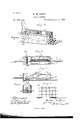
- FIG. 2 is a plan view of the same.
- Fig. 3 is a longitudinal section.
- Fig. 4 is a transverse section through :c x of Fig. 2.
- 'Fig 5 shows the practical application ofthe wire.
- My invention relates to devices for crimping Wire for use in constructing picket and other fences; audit consists in the combination of devices hereinafter explained and claimed.
- A represents a troughshaped box having the rear end, a, open, and the forward end, ⁇ a', closed, but perforated for the passage of the Wire, as shown in Fig. l.
- the rear of the levenhandle the box may be l
- the box may be made to accommodate any desired number of Wires.
- I provide the crimp-guards d d, for holding the crimped Wire steadily in po- 'sition7 so that the crimps, when made, shall all lie in the same vertical plane, as shown in Fig. 5.
- the box A having its front end closed and perforated for the free passage of the wire, and provided with the transverse bar B, in combination with the l
Landscapes
- Engineering & Computer Science (AREA)
- Manufacturing & Machinery (AREA)
- Microelectronics & Electronic Packaging (AREA)
- Connections Effected By Soldering, Adhesion, Or Permanent Deformation (AREA)
Description
(Novrdael.) l
M. M. JONES;
WIRE CRIMPER.
' Patented Apr. l, 1884.
muuu
Illlllll Immune@ llllllllllilllllllIllllllllllli' 27 t UNITED STATES PATENT trice.
MATTHEW JONES, OF KOKOMO, INDIANA.
WIRE-CRHVIPER.
SPECIFICATION forming part of Letters Patent No. 296,177, dated April l, 1884,
(No model.)
1b a/ZZ whom, t may concern:
Be -it Vknown that I, MATTHEW M. JONES, of Kokomo, in the county of Howard and Stat-e of Indiana, have invented a new and useful Improvement in VVireGrimpers, of which the following is a full, clear, and exact description, reference being had to the accompanying drawings, making a part of this specication, in Which- Figure l is a perspective view of my invention. Fig. 2 is a plan view of the same. Fig. 3 is a longitudinal section. Fig. 4 is a transverse section through :c x of Fig. 2. 'Fig 5 shows the practical application ofthe wire.
My invention relates to devices for crimping Wire for use in constructing picket and other fences; audit consists in the combination of devices hereinafter explained and claimed.
To enable others skilled in the art to make and use my invent-ion, I Will proceed to describe the exact manner in which I have carried it out.
In the drawings, A represents a troughshaped box having the rear end, a, open, and the forward end,` a', closed, but perforated for the passage of the Wire, as shown in Fig. l.
'Near the forward end ot' the box is the transverse bar B, on which is pivoted the leverhandle C. This handle is bifurcated and is provided with a cross-bar, c, as shown in Fig. 4. W'hen the handle is in position and pivoted in the box A by the transverse bar B, there is just space enough between the bars B and c to allow of the free passage of' the wire l D when the lever-handle G stands in a vertical position, as shown in Fig. 2. It is now evident that if the lever-handle be forced down, as shown in Fig. 3, the Wire -D Will be crimped, as also shown in the same figure. In
the rear of the levenhandle the box may be l,
vdivided longitudinally,T by the septum E, with a view to operating on two wires at the same time. The box may be made to accommodate any desired number of Wires. In each division of the box I provide the crimp-guards d d, for holding the crimped Wire steadily in po- 'sition7 so that the crimps, when made, shall all lie in the same vertical plane, as shown in Fig. 5.
Having thus explained my invention, what I claim as new, and desire to secure by Let ters Patent, is-
1. In a wire-crimper, the box A, having its front end closed and perforated for the free passage of the wire, and provided with the transverse bar B, in combination with the l
Publications (1)
| Publication Number | Publication Date |
|---|---|
| US296177A true US296177A (en) | 1884-04-01 |
Family
ID=2365363
Family Applications (1)
| Application Number | Title | Priority Date | Filing Date |
|---|---|---|---|
| US296177D Expired - Lifetime US296177A (en) | Wire-crimper |
Country Status (1)
| Country | Link |
|---|---|
| US (1) | US296177A (en) |
Cited By (2)
| Publication number | Priority date | Publication date | Assignee | Title |
|---|---|---|---|---|
| US2621551A (en) * | 1949-06-29 | 1952-12-16 | Ivar V Thulin | Bobby pin reconditioner |
| US4643016A (en) * | 1986-03-14 | 1987-02-17 | Barberine Frank G | Slat bending tool |
-
0
- US US296177D patent/US296177A/en not_active Expired - Lifetime
Cited By (2)
| Publication number | Priority date | Publication date | Assignee | Title |
|---|---|---|---|---|
| US2621551A (en) * | 1949-06-29 | 1952-12-16 | Ivar V Thulin | Bobby pin reconditioner |
| US4643016A (en) * | 1986-03-14 | 1987-02-17 | Barberine Frank G | Slat bending tool |
Similar Documents
| Publication | Publication Date | Title |
|---|---|---|
| US296177A (en) | Wire-crimper | |
| US202786A (en) | Improvement in staple-hooks | |
| US194541A (en) | Improvement in joints for wire and rod fabrics | |
| US180656A (en) | Improvement in barbed fence-wires | |
| US487374A (en) | Fence-stay | |
| US511991A (en) | Pliers for building wire fences | |
| US677396A (en) | Fence-post. | |
| US176575A (en) | Improvement in broilers | |
| US165790A (en) | Improvement in harrows | |
| US180232A (en) | Improvement in bird-cages | |
| US548263A (en) | Wire-bending device | |
| US522578A (en) | Charles h | |
| US182817A (en) | Improvement in barbed metallic fences | |
| US347812A (en) | Spring tug-link | |
| US289076A (en) | Lightning-conductor | |
| US512940A (en) | Twisting-tool for fence-wire | |
| US218506A (en) | Improvement in barbed fence-wire | |
| US348775A (en) | Wire-fence machine | |
| US706385A (en) | Wire-fence clip. | |
| US1285957A (en) | Grooming implement. | |
| US351110A (en) | Self-locking wire picket | |
| US399946A (en) | Wire-tightener | |
| US181433A (en) | Improvement in barbed fence-wire | |
| US195091A (en) | Improvement in barbed-wire fences | |
| US182778A (en) | Improvement in barbed fence-wire |